Skip to content
  • OpenHardware.io
  • Categories
  • Recent
  • Tags
  • Popular
Skins
  • Light
  • Brite
  • Cerulean
  • Cosmo
  • Flatly
  • Journal
  • Litera
  • Lumen
  • Lux
  • Materia
  • Minty
  • Morph
  • Pulse
  • Sandstone
  • Simplex
  • Sketchy
  • Spacelab
  • United
  • Yeti
  • Zephyr
  • Dark
  • Cyborg
  • Darkly
  • Quartz
  • Slate
  • Solar
  • Superhero
  • Vapor

  • Default (No Skin)
  • No Skin
Collapse
Brand Logo
  1. Home
  2. My Project
  3. nRF5 action!
  • Getting Started
  • Controller
  • Build
  • Hardware
  • Download/API
  • Forum
  • Store

nRF5 action!

Scheduled Pinned Locked Moved My Project
1.9k Posts 49 Posters 630.7k Views 44 Watching
  • Oldest to Newest
  • Newest to Oldest
  • Most Votes
Reply
  • Reply as topic
Log in to reply
This topic has been deleted. Only users with topic management privileges can see it.
  • NeverDieN Offline
    NeverDieN Offline
    NeverDie
    Hero Member
    wrote on last edited by NeverDie
    #792

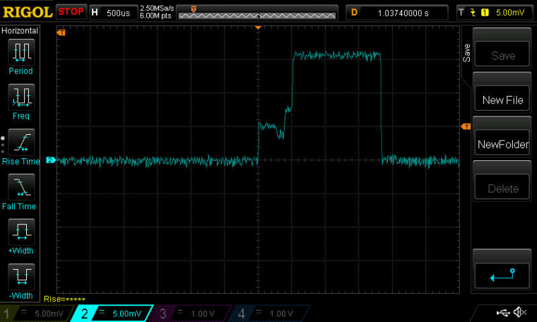
    Sort-of working. Here's a screen shot with the DC/DC modification. Compare to the earlier one above:
    0_1504447563700_NewFile1.jpg
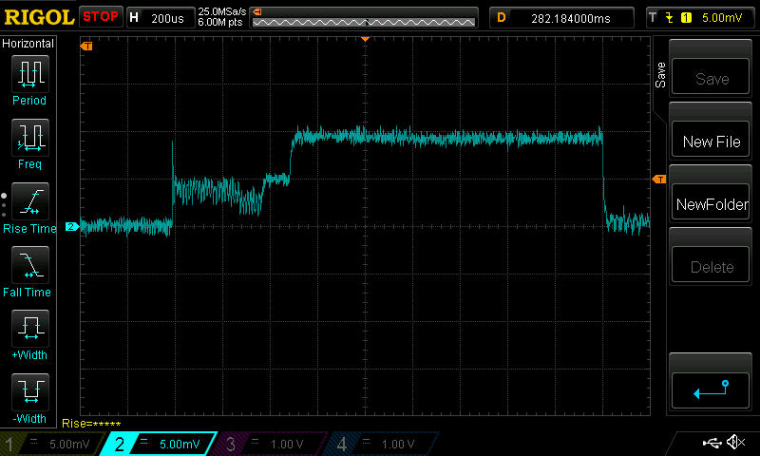
    Probably non-optimal placement of the inductors: between the DCC and DEC4 pins on my breakout board for the nRF52832.

    This is reason enough to do an new version of the breakout for the Ebyte module to improve the inductor positioning.

    Here's the enable code:

      NRF_POWER->DCDCEN=1;  //enable the DCDC voltage regulator as the default.
    

    If it's this easy, I'm just surprised that the module makers haven't included it. The difference in build cost is de minimus, but the difference in delivered value is huge.

    Also, it sounds like I'll have to write a variant of sleep that sleeps just the MPU while leaving the radio in receive mode. That's an easy win to improve the current consumption.

    1 Reply Last reply
    1
    • NeverDieN Offline
      NeverDieN Offline
      NeverDie
      Hero Member
      wrote on last edited by NeverDie
      #793

      Good news! I went back and re-rechecked using an un-modified Ebyte module, and, indeed, this time I'm sure that the DCDC inductors are already on it! What follows is the proof. Here is the current drawn when the above DCDCEN is enabled on an unmodified Ebyte module:

      0_1504461945615_NewFile2.jpg

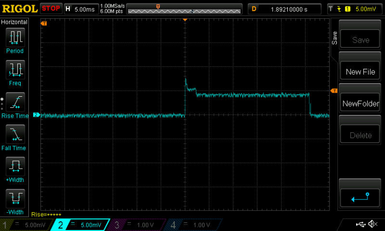
      Now, here is the current drawn with the exact same script on the exact same unmodified Ebyte module, but with the DCDCEN line of code commented out:
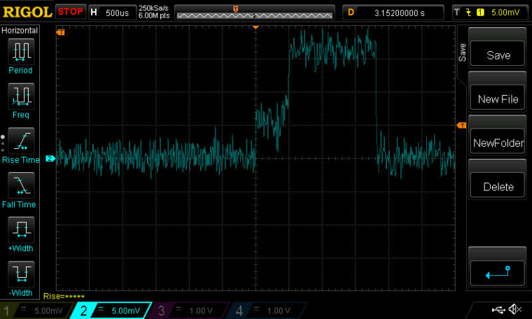
      0_1504461988147_NewFile3.jpg

      QED.

      As you can see, the savings in current consumption are considerable with the DCDC enabled!

      [Edit: although looking at it again, the timescale seems way off. Argh. Something still isn't right.]

      1 Reply Last reply
      0
      • NeverDieN Offline
        NeverDieN Offline
        NeverDie
        Hero Member
        wrote on last edited by
        #794

        Scratch the preceeding post. I redid it more carefully this time, and I believe it confirms that the Ebyte module does not have the two inductors required for DC/DC mode.

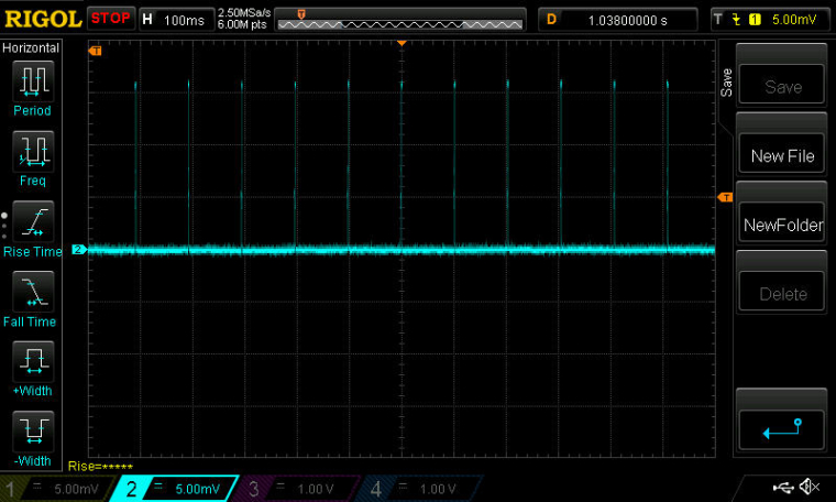
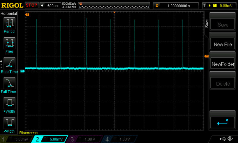
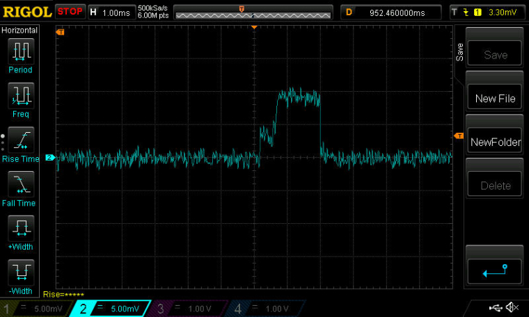
        Here is the current drawn by an unmodified Ebyte nRF52832 module which is programmed to be receiving for about 1.5ms every 100ms:
        0_1504472450738_NewFile1.jpg
        0_1504472465572_NewFile2.jpg

        1 Reply Last reply
        1
        • NeverDieN Offline
          NeverDieN Offline
          NeverDie
          Hero Member
          wrote on last edited by NeverDie
          #795

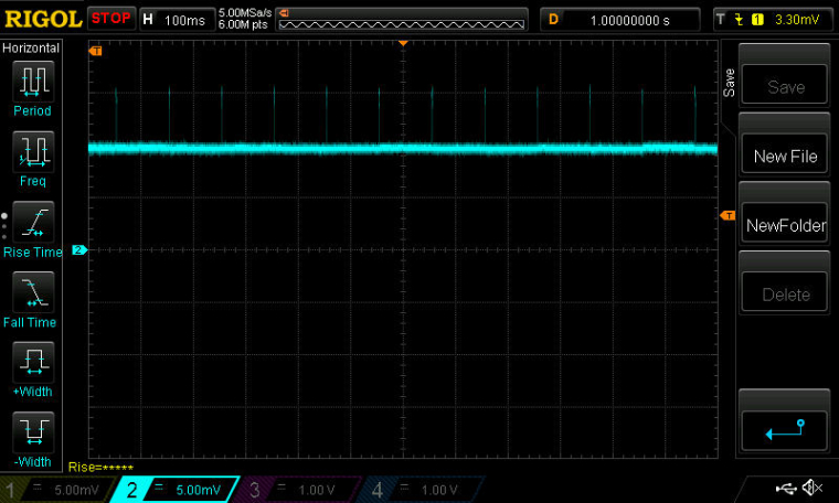
          Here is what happens with exactly the same hardware (no inductors yet added), but with DCDCEN enabled:
          0_1504472667206_NewFile3.jpg

          0_1504472696820_NewFile4.jpg
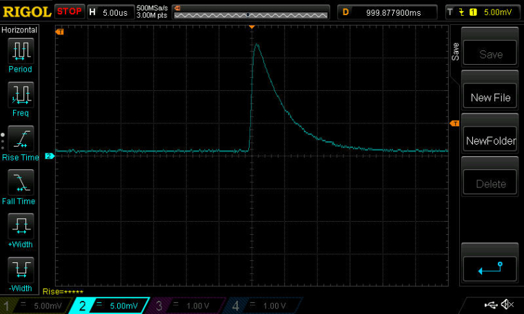
          It basically seems caught in a boot loop.

          1 Reply Last reply
          0
          • NeverDieN Offline
            NeverDieN Offline
            NeverDie
            Hero Member
            wrote on last edited by NeverDie
            #796

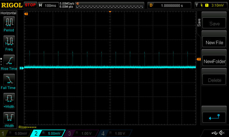
            Now, adding the two inductors between DCC and DEC4, and re-measuring, we get:
            0_1504472770946_NewFile1.jpg

            0_1504472782958_NewFile2.jpg

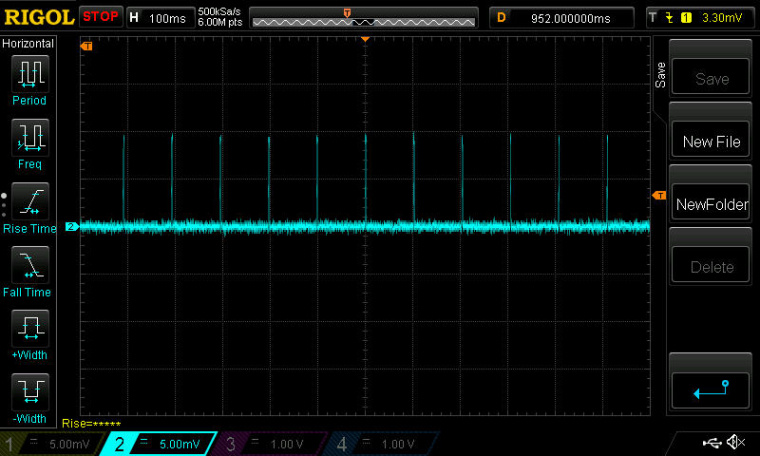
            No less importantly, it does receive and decode packets!

            Conclusion: Ebyte nRF52832 modules don't come with the DC/DC inductors already installed. However, they can be added, resulting in some current reduction.

            1 Reply Last reply
            0
            • NeverDieN Offline
              NeverDieN Offline
              NeverDie
              Hero Member
              wrote on last edited by NeverDie
              #797

              I've baked these findings into a new breakout board for the Ebyte nRF52832:
              https://www.openhardware.io/view/471
              The new breakout board will enable the module to work in DC/DC mode.

              1 Reply Last reply
              0
              • NeverDieN Offline
                NeverDieN Offline
                NeverDie
                Hero Member
                wrote on last edited by NeverDie
                #798

                I may have found a clue as to why the reset pin (pin0.21) on the nRF52832 isn't working.

                On the nRF52832 DK, I read the following register values:
                PSELRESET[0]=21
                PSELRESET[1]=21

                which is as expected. However, on the Ebyte nRF52832 module, I read those register values as:
                PSELRESET[0]=4294967295
                PSELRESET[1]=4294967295

                which makes no sense. The values match, but they don't correspond to a pin number that can represent RESET.

                These two registers are described in the nRF52832 datasheet.

                mfalkviddM 1 Reply Last reply
                0
                • NeverDieN NeverDie

                  I may have found a clue as to why the reset pin (pin0.21) on the nRF52832 isn't working.

                  On the nRF52832 DK, I read the following register values:
                  PSELRESET[0]=21
                  PSELRESET[1]=21

                  which is as expected. However, on the Ebyte nRF52832 module, I read those register values as:
                  PSELRESET[0]=4294967295
                  PSELRESET[1]=4294967295

                  which makes no sense. The values match, but they don't correspond to a pin number that can represent RESET.

                  These two registers are described in the nRF52832 datasheet.

                  mfalkviddM Offline
                  mfalkviddM Offline
                  mfalkvidd
                  Mod
                  wrote on last edited by
                  #799

                  @NeverDie not sure if you've already noticed, but 4294967295 is the maximum value for an unsigned 32-bit integer. So the value is 0xFFFFFFFF. That often means uninitialized. I don't know why it would be uninitialized though.

                  NeverDieN 2 Replies Last reply
                  3
                  • mfalkviddM mfalkvidd

                    @NeverDie not sure if you've already noticed, but 4294967295 is the maximum value for an unsigned 32-bit integer. So the value is 0xFFFFFFFF. That often means uninitialized. I don't know why it would be uninitialized though.

                    NeverDieN Offline
                    NeverDieN Offline
                    NeverDie
                    Hero Member
                    wrote on last edited by NeverDie
                    #800

                    @mfalkvidd

                    Maybe because they just never were?
                    Those particular registers are "The user information configuration registers (UICRs) are non-volatile memory (NVM) registers for configuring user specific settings." So, it would seem that initializing them just once would be enough, since they're non-volatile.

                    In any case, good catch! It explains both why they are that value and also why they match.

                    1 Reply Last reply
                    1
                    • NeverDieN Offline
                      NeverDieN Offline
                      NeverDie
                      Hero Member
                      wrote on last edited by NeverDie
                      #801

                      @NeverDie said in nRF5 Bluetooth action!:

                      4294967295

                      Also, since 4294967295 equals 0xFFFFFFFF, then bit 31 is a '1', which, according to the datasheet, means the pin is disconnected (see section 14.1.60 PSELRESET[0] of the datasheet for the detail].

                      1 Reply Last reply
                      0
                      • mfalkviddM mfalkvidd

                        @NeverDie not sure if you've already noticed, but 4294967295 is the maximum value for an unsigned 32-bit integer. So the value is 0xFFFFFFFF. That often means uninitialized. I don't know why it would be uninitialized though.

                        NeverDieN Offline
                        NeverDieN Offline
                        NeverDie
                        Hero Member
                        wrote on last edited by
                        #802

                        @mfalkvidd said in nRF5 Bluetooth action!:

                        So the value is 0xFFFFFFFF. That often means uninitialized. I don't know why it would be uninitialized though.

                        There's a chance we may have unwittingly done it ourselves! Remember back to when we were doing an explicit "Erase All"? From the datasheet:

                        11.5 Erase all
                        When erase is enabled, the whole Flash and UICR can be erased in one operation by using the ERASEALL
                        register.

                        Furthermore, from page 29 of the datasheet:

                        After erasing UICR all bits in UICR are set to '1'.

                        d00616D 1 Reply Last reply
                        0
                        • NeverDieN NeverDie

                          @mfalkvidd said in nRF5 Bluetooth action!:

                          So the value is 0xFFFFFFFF. That often means uninitialized. I don't know why it would be uninitialized though.

                          There's a chance we may have unwittingly done it ourselves! Remember back to when we were doing an explicit "Erase All"? From the datasheet:

                          11.5 Erase all
                          When erase is enabled, the whole Flash and UICR can be erased in one operation by using the ERASEALL
                          register.

                          Furthermore, from page 29 of the datasheet:

                          After erasing UICR all bits in UICR are set to '1'.

                          d00616D Offline
                          d00616D Offline
                          d00616
                          Contest Winner
                          wrote on last edited by
                          #803

                          @NeverDie said in nRF5 Bluetooth action!:

                          @mfalkvidd said in nRF5 Bluetooth action!:

                          So the value is 0xFFFFFFFF. That often means uninitialized. I don't know why it would be uninitialized though.

                          There's a chance we may have unwittingly done it ourselves! Remember back to when we were doing an explicit "Erase All"? From the datasheet:

                          This is part of the arduino-nrf5 code -> https://github.com/sandeepmistry/arduino-nRF5/blob/dc53980c8bac27898fca90d8ecb268e11111edc1/cores/nRF5/SDK/components/toolchain/system_nrf52.c#L156

                          I don't have any idea why this is not included in the binary. When the reset menu is selected then "-DCONFIG_GPIO_AS_PINRESET" is given to gcc.

                          When system_nrf52.c is completely ignored, then the erratas are not handled.

                          1 Reply Last reply
                          0
                          • NeverDieN Offline
                            NeverDieN Offline
                            NeverDie
                            Hero Member
                            wrote on last edited by NeverDie
                            #804

                            Here is some verbose code which properly sets the registers to use pin P0.21 as the RESET pin:

                            Serial.println("Testing...");
                            delay(10000);  //give preparation time to open serial tty
                            Serial.print(counter);
                            Serial.print(", PSELRESET[0]=");
                            Serial.println(NRF_UICR-> PSELRESET[0]);
                            Serial.print(counter++);
                            Serial.print(", PSELRESET[1]=");
                            Serial.println(NRF_UICR-> PSELRESET[1]);
                            
                            Serial.println();
                            Serial.println("Write-enabling CONFIG.");
                            NRF_NVMC->CONFIG=1;  // Write enable the UICR
                            
                            Serial.println();
                            Serial.println("Now designating pin pO.21 as the RESET pin.");
                            NRF_UICR-> PSELRESET[0]=21;  //designate pin pO.21 as the RESET pin
                            NRF_UICR-> PSELRESET[1]=21;  //designate pin pO.21 as the RESET pin
                            
                            Serial.println();
                            Serial.println("Confirming that RESET pin assigment took hold:");
                            Serial.print(counter);
                            Serial.print(", PSELRESET[0]=");
                            Serial.println(NRF_UICR-> PSELRESET[0]);
                            Serial.print(counter++);
                            Serial.print(", PSELRESET[1]=");
                            Serial.println(NRF_UICR-> PSELRESET[1]);
                            
                            Serial.println();
                            Serial.println("Return CONFIG to read-only mode.");
                            NRF_NVMC->CONFIG=0;  // Put the UICR back into read-only mode.
                            

                            Running it once seems to be good enough, unless there were to occur another "Erase All" or "Burn bootloader" event.

                            Here is the output from running the code which shows that it succeeded:

                            Testing...
                            0, PSELRESET[0]=4294967295
                            0, PSELRESET[1]=4294967295
                            
                            Write-enabling CONFIG.
                            
                            Now designating pin pO.21 as the RESET pin.
                            
                            Confirming that RESET pin assigment took hold:
                            1, PSELRESET[0]=21
                            1, PSELRESET[1]=21
                            
                            Return CONFIG to read-only mode.
                            
                            1 Reply Last reply
                            0
                            • NeverDieN Offline
                              NeverDieN Offline
                              NeverDie
                              Hero Member
                              wrote on last edited by NeverDie
                              #805

                              Until a more elegant solution can be found, I'm using this in the setup() routine as the workaround:

                                if (((NRF_UICR-> PSELRESET[0])==0xFFFFFFFF) && ((NRF_UICR-> PSELRESET[1])==0xFFFFFFFF)) { //if the two RESET registers are erased
                                  NRF_NVMC->CONFIG=1;  // Write enable the UICR
                                  NRF_UICR-> PSELRESET[0]=21;  //designate pin P0.21 as the RESET pin
                                  NRF_UICR-> PSELRESET[1]=21;  //designate pin P0.21 as the RESET pin
                                  NRF_NVMC->CONFIG=0;  // Put the UICR back into read-only mode.
                                }
                              

                              The code has the positive virtue of not writing to the RESET rregisters unless both registers are erased. That helps ensure that the non-volatile memory does not get worn out prematurely.

                              NeverDieN 1 Reply Last reply
                              0
                              • NeverDieN NeverDie

                                Until a more elegant solution can be found, I'm using this in the setup() routine as the workaround:

                                  if (((NRF_UICR-> PSELRESET[0])==0xFFFFFFFF) && ((NRF_UICR-> PSELRESET[1])==0xFFFFFFFF)) { //if the two RESET registers are erased
                                    NRF_NVMC->CONFIG=1;  // Write enable the UICR
                                    NRF_UICR-> PSELRESET[0]=21;  //designate pin P0.21 as the RESET pin
                                    NRF_UICR-> PSELRESET[1]=21;  //designate pin P0.21 as the RESET pin
                                    NRF_NVMC->CONFIG=0;  // Put the UICR back into read-only mode.
                                  }
                                

                                The code has the positive virtue of not writing to the RESET rregisters unless both registers are erased. That helps ensure that the non-volatile memory does not get worn out prematurely.

                                NeverDieN Offline
                                NeverDieN Offline
                                NeverDie
                                Hero Member
                                wrote on last edited by NeverDie
                                #806

                                @NeverDie said in nRF5 Bluetooth action!:

                                Until a more elegant solution can be found, I'm using this in the setup() routine as the workaround:

                                  if (((NRF_UICR-> PSELRESET[0])==0xFFFFFFFF) && ((NRF_UICR-> PSELRESET[1])==0xFFFFFFFF)) { //if the two RESET registers are erased
                                    NRF_NVMC->CONFIG=1;  // Write enable the UICR
                                    NRF_UICR-> PSELRESET[0]=21;  //designate pin P0.21 as the RESET pin
                                    NRF_UICR-> PSELRESET[1]=21;  //designate pin P0.21 as the RESET pin
                                    NRF_NVMC->CONFIG=0;  // Put the UICR back into read-only mode.
                                  }
                                

                                The code has the positive virtue of not writing to the RESET rregisters unless both registers are erased. That helps ensure that the non-volatile memory does not get worn out prematurely.

                                Good news! I've confirmed that doing this does indeed solve the problem I previously had with the EByte nRF52832 module not reacting to a reset on pin P0.21. After inserting the above code block into the nRF52832's setup() routine, I can now, using ESP-LINK, remotely reset an nRF52832 module:
                                https://www.openhardware.io/view/443/nRF52832-ESP-LINK-Shield-for-ESP8266-Wemos-D1-Mini

                                1 Reply Last reply
                                0
                                • NeverDieN Offline
                                  NeverDieN Offline
                                  NeverDie
                                  Hero Member
                                  wrote on last edited by NeverDie
                                  #807

                                  With that issue now settled, I'm moving on to a different topic: what happens if you put the radio into Tx mode, but with an empty buffer (i.e. nothing to send)? In this scenario an RFM69 transmits a continuous pre-amble, and I'm wondering whether the nRF52832 does the same?
                                  With an empty buffer, does it transmit anything at all? Anyone happen to know?

                                  The reason I ask is that I want to program the radio to send a continuous signal so as to quickly wake-up a receiver. With packets, there's the lag time of receiving and decoding the packet, rather than just reacting to a high RSSI. In this way, I can use much narrower listen windows and thereby save a lot of current consumption.

                                  1 Reply Last reply
                                  1
                                  • NeverDieN Offline
                                    NeverDieN Offline
                                    NeverDie
                                    Hero Member
                                    wrote on last edited by
                                    #808

                                    According to the datasheet, the typical RSSI sample period is just 0.25us. However, what spoils that a bit is that the radio has to come up to speed beforehand.

                                    Anyhow, on the receive side, I now have at least that much working.

                                    1 Reply Last reply
                                    0
                                    • NeverDieN Offline
                                      NeverDieN Offline
                                      NeverDie
                                      Hero Member
                                      wrote on last edited by
                                      #809

                                      It looks as though the start-up time for the radio is about 390us. So, it does save a lot of current to first check the RSSI level rather than to always listen for a packet.

                                      1 Reply Last reply
                                      0
                                      • NeverDieN Offline
                                        NeverDieN Offline
                                        NeverDie
                                        Hero Member
                                        wrote on last edited by NeverDie
                                        #810

                                        When I measure RSSI on the nRF52832, I get what seems like a rather odd range of values: between about 94 and 127. If I have no other nodes transmitting, then the RSSI is generally around 100. If I set up another node which deliberately transmits on the same channel, then the RSSI is pegged at 127.

                                        Is that what others here are also seeing? Here's the test code:

                                        uint8_t theRSSI;
                                        void loop() {
                                          
                                        NRF_RADIO->TASKS_RXEN=1;  //start revving up the receiver
                                        while (!(NRF_RADIO->EVENTS_READY)) {} //busy-wait until radio ready to receive
                                        NRF_RADIO->TASKS_RSSISTART=1;  //Take exactly one RSSI sample
                                        while (!(NRF_RADIO->EVENTS_RSSIEND)) {}  //Busy-wait until RSSI sample is completed.
                                        theRSSI = NRF_RADIO->RSSISAMPLE;
                                        
                                        Serial.println(theRSSI);
                                        Serial.flush();
                                        sleep(1000);
                                        }
                                        
                                        1 Reply Last reply
                                        0
                                        • NeverDieN Offline
                                          NeverDieN Offline
                                          NeverDie
                                          Hero Member
                                          wrote on last edited by NeverDie
                                          #811

                                          Unfortunately, when I use the above code block and test the current using an oscilliscope, it becomes clear that the radio never actually goes to sleep:

                                          0_1504740304312_NewFile1.jpg
                                          So, to do that, I add the line:

                                          NRF_RADIO->TASKS_DISABLE=1;  //turn-off the radio
                                          

                                          just prior to sleep(100). Doing that largely eliminates the current drain while sleeping:
                                          0_1504740345602_NewFile3.jpg

                                          However, if I do that, then the RSSI that gets reported is always 127. Why? Do I need some other way to check the radio states? Maybe STATE from section 23.14.25 STATE of the datasheet would work better?

                                          1 Reply Last reply
                                          0
                                          Reply
                                          • Reply as topic
                                          Log in to reply
                                          • Oldest to Newest
                                          • Newest to Oldest
                                          • Most Votes


                                          10

                                          Online

                                          11.7k

                                          Users

                                          11.2k

                                          Topics

                                          113.0k

                                          Posts


                                          Copyright 2019 TBD   |   Forum Guidelines   |   Privacy Policy   |   Terms of Service
                                          • Login

                                          • Don't have an account? Register

                                          • Login or register to search.
                                          • First post
                                            Last post
                                          0
                                          • OpenHardware.io
                                          • Categories
                                          • Recent
                                          • Tags
                                          • Popular