nRF5 action!
-
@NeverDie said in nRF5 Bluetooth action!:
@Mike_Lemo said in nRF5 Bluetooth action!:
Any idea how I reach to this code?
Yes, it's all explained in detail by @d00616 here: https://www.openhardware.io/view/376/MySensors-NRF5-Platform
Also you say you don't experience any issues with I2C like that?
Haven't tried I2C on this platform yet. I'd be very surprised if it didn't work though, as that's ARM Cortex M4 stuff, which is well vetted. i.e. no real dependency on anything Nordic per se.
The link you attached links me to a getting started page not wireing two nrf's together
@Mike_Lemo said in nRF5 Bluetooth action!:
The link you attached links me to a getting started page not wireing two nrf's together
Your question was ambiguous. When you said "connect" I just assumed you meant wirelessly connect.
Sorry, I can't help you. Seems like @scalz has gotten I2C to work with it though, but more likely for reading a TH sensor than for the purpose of wiring two nRF52832's. Still, that would prove that it works. If you know the I2C protocol, it shouldn't be hard to go from that to wiring two nRF52832's together.
-
Here's a scopeshot of how the revised current draw looks:
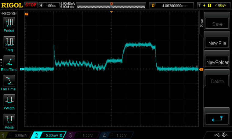
As you can see, there is now about a 370us warm-up time at the beginning for the High Frequency oscillator to come up to speed before the RX cycle can be started. Then it takes about 100us for the receiver to warm-up to RXIDLE. From there it finally achieves about 200us of actual productive RX time. Then everything powers down until the end of the 100ms cycle, after which it all repeats again. To conserve energy, all this is managed by the PPI while the MCU sleeps.
Scale: 1mv=1maI think this is about as energy efficient as it's ever going to get, short of chipping away at the number of bits in the frame/packet size, as I indicated earlier.
@NeverDie said in nRF5 Bluetooth action!:
I think this is about as energy efficient as it's ever going to get, short of chipping away at the number of bits in the frame/packet size, as I indicated earlier.
I also measured the current between the peaks shown in the scopeshot. By increasing the period between listens, I was able to do the measurement using a uCurrent Gold. Doing so, I found that the current drawn was 10.7ua using the Low Frequency crystal oscillator, and 11.2ua using the Low Frequency RC oscillator. I'm now sure how to square that with some of the earlier measurements I had taken with the nRF52832 sleeping using the MySensors sleep routine, as those measurements came out to about 6ua. Perhaps the difference is the extra current required to run the PPI in this configuration? With neither oscillator configured, and no PPI, it measures, as I said earlier, at 2.2ua, which is close to what the datasheet predicts.
-
@NeverDie said in nRF5 Bluetooth action!:
@Mike_Lemo said in nRF5 Bluetooth action!:
Any idea how I reach to this code?
Yes, it's all explained in detail by @d00616 here: https://www.openhardware.io/view/376/MySensors-NRF5-Platform
Also you say you don't experience any issues with I2C like that?
Haven't tried I2C on this platform yet. I'd be very surprised if it didn't work though, as that's ARM Cortex M4 stuff, which is well vetted. i.e. no real dependency on anything Nordic per se.
The link you attached links me to a getting started page not wireing two nrf's together
@Mike_Lemo said in nRF5 Bluetooth action!:
@NeverDie said in nRF5 Bluetooth action!:
@Mike_Lemo said in nRF5 Bluetooth action!:
Any idea how I reach to this code?
Yes, it's all explained in detail by @d00616 here: https://www.openhardware.io/view/376/MySensors-NRF5-Platform
Also you say you don't experience any issues with I2C like that?
Haven't tried I2C on this platform yet. I'd be very surprised if it didn't work though, as that's ARM Cortex M4 stuff, which is well vetted. i.e. no real dependency on anything Nordic per se.
The link you attached links me to a getting started page not wireing two nrf's together
Yes I did mean wirelessly like central and peripherial connection... Is that supported?
-
I'm sorry, but I can't help you any more than I already have.
-
Here's a scopeshot of how the revised current draw looks:
As you can see, there is now about a 370us warm-up time at the beginning for the High Frequency oscillator to come up to speed before the RX cycle can be started. Then it takes about 100us for the receiver to warm-up to RXIDLE. From there it finally achieves about 200us of actual productive RX time. Then everything powers down until the end of the 100ms cycle, after which it all repeats again. To conserve energy, all this is managed by the PPI while the MCU sleeps.
Scale: 1mv=1maI think this is about as energy efficient as it's ever going to get, short of chipping away at the number of bits in the frame/packet size, as I indicated earlier.
@NeverDie said in nRF5 Bluetooth action!:
I think this is about as energy efficient as it's ever going to get
Epilog: I ran it overnight on a 10F capacitor, and it dropped only 0.011v per hour. I'm very happy with that, considering it's listening every 100ms as to whether or not it has received a packet. :)
-
@d00616 Your posting says,
At the moment on Arduino, there is no definition of various OUTPUT modes. If you want to access all nRF5 output modes, you have to use hwPinMode and the OUTPUT_... macro.
Exactly which macro would that be? It looks to me as though what most users will want is the function nrf5_pinmode(..,..), which appears to do all the actual work. Is that right? It is defined in the file nrf5_wiring_digital.c.
Meanwhile, hwPinMode appears to be merely a straight pass-through for pinMode:
void hwPinMode(uint8_t pin, uint8_t mode) { pinMode(pin, mode); } -
Where is it possible to find a reference schematic for using the NTF52832 E73-2G4M04S module with NFC?
not much is being given in the datasheet not even where the NFC pins go.
@Mike_Lemo said in nRF5 Bluetooth action!:
Where is it possible to find a reference schematic for using the NTF52832 E73-2G4M04S module with NFC?
not much is being given in the datasheet not even where the NFC pins go.Please look into the product documentation:
http://infocenter.nordicsemi.com/topic/com.nordic.infocenter.nrf52832.ps.v1.1/nfc.html?cp=2_1_0_41_8#concept_ryw_4hk_1s@NeverDie said in nRF5 Bluetooth action!:
At the moment on Arduino, there is no definition of various OUTPUT modes. If you want to access all nRF5 output modes, you have to use hwPinMode and the OUTPUT_... macro.
Exactly which macro would that be? It looks to me as though what most users will want is the function nrf5_pinmode(..,..), which appears to do all the actual work. Is that right? It is defined in the file nrf5_wiring_digital.c.
hwPinMode allows to define platform specific PinMode replacements. Code may be portable. This is the reason pointing to nrf5_pinmode().
nrf5_pinmode() has a little bit more functionality than the original pinmode function.
Meanwhile, hwPinMode appears to be merely a straight pass-through for pinMode:
void hwPinMode(uint8_t pin, uint8_t mode)
{
pinMode(pin, mode);
}This disables the capability using nRF5 specific pin modes with the MySensors API.
-
@Mike_Lemo said in nRF5 Bluetooth action!:
Where is it possible to find a reference schematic for using the NTF52832 E73-2G4M04S module with NFC?
not much is being given in the datasheet not even where the NFC pins go.Please look into the product documentation:
http://infocenter.nordicsemi.com/topic/com.nordic.infocenter.nrf52832.ps.v1.1/nfc.html?cp=2_1_0_41_8#concept_ryw_4hk_1s@NeverDie said in nRF5 Bluetooth action!:
At the moment on Arduino, there is no definition of various OUTPUT modes. If you want to access all nRF5 output modes, you have to use hwPinMode and the OUTPUT_... macro.
Exactly which macro would that be? It looks to me as though what most users will want is the function nrf5_pinmode(..,..), which appears to do all the actual work. Is that right? It is defined in the file nrf5_wiring_digital.c.
hwPinMode allows to define platform specific PinMode replacements. Code may be portable. This is the reason pointing to nrf5_pinmode().
nrf5_pinmode() has a little bit more functionality than the original pinmode function.
Meanwhile, hwPinMode appears to be merely a straight pass-through for pinMode:
void hwPinMode(uint8_t pin, uint8_t mode)
{
pinMode(pin, mode);
}This disables the capability using nRF5 specific pin modes with the MySensors API.
@d00616 said in nRF5 Bluetooth action!:
@Mike_Lemo said in nRF5 Bluetooth action!:
Where is it possible to find a reference schematic for using the NTF52832 E73-2G4M04S module with NFC?
not much is being given in the datasheet not even where the NFC pins go.Please look into the product documentation:
http://infocenter.nordicsemi.com/topic/com.nordic.infocenter.nrf52832.ps.v1.1/nfc.html?cp=2_1_0_41_8#concept_ryw_4hk_1s@NeverDie said in nRF5 Bluetooth action!:
At the moment on Arduino, there is no definition of various OUTPUT modes. If you want to access all nRF5 output modes, you have to use hwPinMode and the OUTPUT_... macro.
Exactly which macro would that be? It looks to me as though what most users will want is the function nrf5_pinmode(..,..), which appears to do all the actual work. Is that right? It is defined in the file nrf5_wiring_digital.c.
hwPinMode allows to define platform specific PinMode replacements. Code may be portable. This is the reason pointing to nrf5_pinmode().
nrf5_pinmode() has a little bit more functionality than the original pinmode function.
Meanwhile, hwPinMode appears to be merely a straight pass-through for pinMode:
void hwPinMode(uint8_t pin, uint8_t mode)
{
pinMode(pin, mode);
}This disables the capability using nRF5 specific pin modes with the MySensors API.
I'm talking about the module it's self isn't there a reference schematic for that? I see there are some component in there but else do I have to add to make this work?
-
@Mike_Lemo said in nRF5 Bluetooth action!:
@NeverDie said in nRF5 Bluetooth action!:
@Mike_Lemo said in nRF5 Bluetooth action!:
Any idea how I reach to this code?
Yes, it's all explained in detail by @d00616 here: https://www.openhardware.io/view/376/MySensors-NRF5-Platform
Also you say you don't experience any issues with I2C like that?
Haven't tried I2C on this platform yet. I'd be very surprised if it didn't work though, as that's ARM Cortex M4 stuff, which is well vetted. i.e. no real dependency on anything Nordic per se.
The link you attached links me to a getting started page not wireing two nrf's together
Yes I did mean wirelessly like central and peripherial connection... Is that supported?
@Mike_Lemo said in nRF5 Bluetooth action!:
Yes I did mean wirelessly like central and peripherial connection... Is that supported?
You're mixing things maybe. You're talking about bluetooth. that's not Mysensors ;)
But if you want to get a connection between two nrf52832 or nrf52832/nrf24, take a look at d00616 docs.a nrf52 is a nrf52, no matter the module.
So nfc pins (which are fixed) will be the same on every nrf52 you'll find. It can just happen that you get a board where those pins are used for other purpose (then you can't use nfc without little hack).
But regarding the cdebyte modules, these are simply nrf52 with pinout. So no problem here. Just take a look at the nordic link d00616 showed about using nfc.
In case.. pins are P0.09 and P0.10. But you'll need to tune your nfc antenna, and add capacitors. Sparkfun, adafruit have some infos on this as they're selling boards.
-
Also, if you're interested in NFC, the Nordic nRF52832 DK comes with an antenna for it. It would probably be the easiest to use, because a connector for the antenna is already on the board.
-
@Mike_Lemo said in nRF5 Bluetooth action!:
Yes I did mean wirelessly like central and peripherial connection... Is that supported?
You're mixing things maybe. You're talking about bluetooth. that's not Mysensors ;)
But if you want to get a connection between two nrf52832 or nrf52832/nrf24, take a look at d00616 docs.a nrf52 is a nrf52, no matter the module.
So nfc pins (which are fixed) will be the same on every nrf52 you'll find. It can just happen that you get a board where those pins are used for other purpose (then you can't use nfc without little hack).
But regarding the cdebyte modules, these are simply nrf52 with pinout. So no problem here. Just take a look at the nordic link d00616 showed about using nfc.
In case.. pins are P0.09 and P0.10. But you'll need to tune your nfc antenna, and add capacitors. Sparkfun, adafruit have some infos on this as they're selling boards.
Yeah but my question was about what is connected in the module and what components I have to use....
Also about the NFC I'm planning to use it with the arduino IDE so just wanted to ask if there is a library for it because the SDK is quite useless in this case as well as the Central peripheral connection.
-
Yeah but my question was about what is connected in the module and what components I have to use....
Also about the NFC I'm planning to use it with the arduino IDE so just wanted to ask if there is a library for it because the SDK is quite useless in this case as well as the Central peripheral connection.
@Mike_Lemo said in nRF5 Bluetooth action!:
Also about the NFC I'm planning to use it with the arduino IDE so just wanted to ask if there is a library for it because the SDK is quite useless in this case as well as the Central peripheral connection.
Now there is a second port of arduino to nRF52. This includes some libraries, like NFC, but they using the SDK. MySensors is currently not ready for this arduino-port.
-
I was able to reduce the active listen period to about 100us:
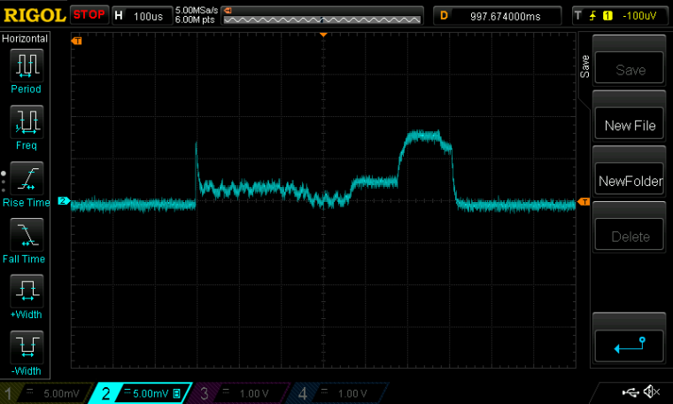
Now listening every 100ms yields a 10F supercap voltage measured decline of just 9mv per hour. i.e. a decline of 0.108v by the end of 12 hours.@NeverDie said in nRF5 Bluetooth action!:
Now listening every 100ms yields a 10F supercap voltage measured decline of just 9mv per hour. i.e. a decline of 0.108v by the end of 12 hours.
Great job. If I'm not wrong the method allows nearly 1 year of listening time with a CR2032.
-
Where is it possible to find a reference schematic for using the NTF52832 E73-2G4M04S module with NFC?
not much is being given in the datasheet not even where the NFC pins go.
@Mike_Lemo your best bet is to "convert" the module to Arduino Primo and use the NFC libraries developed for it.
d00616 gave you the link to the arduino org github. Pls. note that Primo core generates a merged softdevice+sketch hex so you should locate it in the Temp folder and upload. -
Here's a very simple OPEN/CLOSE remote control I was able to quickly throw together using my small prototyping board:
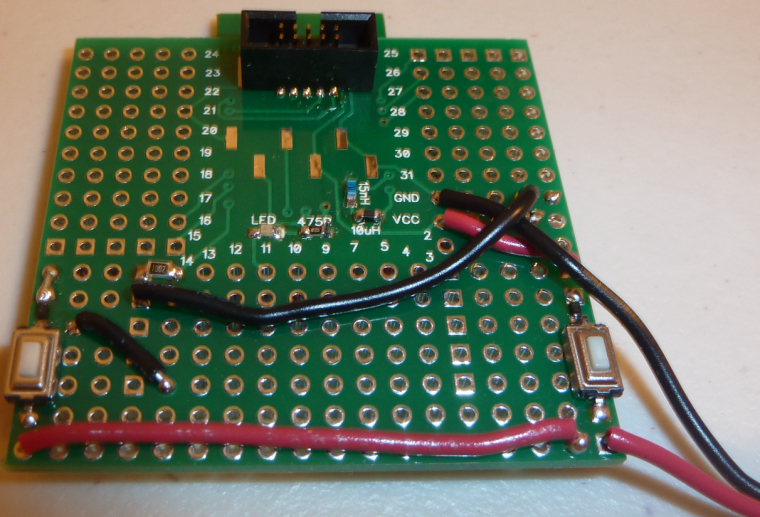
It required only two buttons, a diode, a resistor, and (obviously) some wire. When not in use, everything is powered 100% OFF to save the most energy possible. So, pushing either button powers it ON, at which point it rapidly determines which button was pushed and then sends the corresponding packet to the receiver. From the standpoint of human perception, it all appears to happen instantly. -
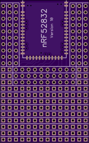
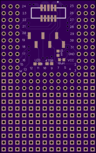
This is how the next version of the protoboard will look:
-
Interestingly, it looks as though Arduino is suggesting/recommending users to use the regular Arduino Primo to program the Arduino Primo Core (i.e. the wearable).
-
Interestingly, it looks as though Arduino is suggesting/recommending users to use the regular Arduino Primo to program the Arduino Primo Core (i.e. the wearable).
