nRF5 action!
-
@Toyman said in nRF5 Bluetooth action!:
@NeverDie is this SWD?
I don't have either the Primo or the Primo Core, so I can't say for sure. However, I presume so.
-
Did anyone managed to get two NRF52832 to connect to each other with the arduino IDE and communicate?
Also why does I2C initializes only after an SWD programmed gets connected?
Wierd phenomenon when I use an I2C oled display with that chip and program it with an st link V2 after it displays alright when it's booted if the SWD programmer is connected but as soon as you disconnect it everything else works but the I2C display...
@Mike_Lemo
This sounds more like an EMC issue.
The connected ST Link filters some disturbance at the i2c lines, and when it's not connected, the disturbance corrupts the signals.
Try connecting capacitors from the i2c lines to ground. I'd start with 100pF each.
May also be a power supply issue. Did you connect the st-link's 3.3V line to the board? -
Here's the small budget nRF51 soldered to the breakout board that I had linked earlier above:
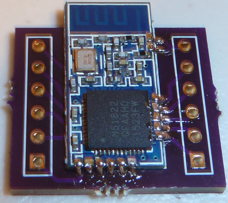
I have the RTC running off the low frequency internal RC, because I don't see a crystal oscillator on the module. I have it blinking an LED now and sending text to the serial port, which I'm able to read on the serial console.
At least so far, all is good. :)
-
Here's a very simple OPEN/CLOSE remote control I was able to quickly throw together using my small prototyping board:
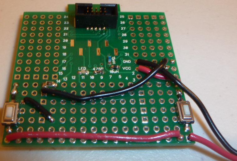
It required only two buttons, a diode, a resistor, and (obviously) some wire. When not in use, everything is powered 100% OFF to save the most energy possible. So, pushing either button powers it ON, at which point it rapidly determines which button was pushed and then sends the corresponding packet to the receiver. From the standpoint of human perception, it all appears to happen instantly.@NeverDie said in nRF5 Bluetooth action!:
Here's a very simple OPEN/CLOSE remote control I was able to quickly throw together using my small prototyping board:
It required only two buttons, a diode, a resistor, and (obviously) some wire. When not in use, everything is powered 100% OFF to save the most energy possible. So, pushing either button powers it ON, at which point it rapidly determines which button was pushed and then sends the corresponding packet to the receiver. From the standpoint of human perception, it all appears to happen instantly.Hello @NeverDie, could you please share the code for this ?
I'd like to adapt and test it on a reprogrammed nrf51822 beacon that I just received. -
@NeverDie said in nRF5 Bluetooth action!:
Here's a very simple OPEN/CLOSE remote control I was able to quickly throw together using my small prototyping board:
It required only two buttons, a diode, a resistor, and (obviously) some wire. When not in use, everything is powered 100% OFF to save the most energy possible. So, pushing either button powers it ON, at which point it rapidly determines which button was pushed and then sends the corresponding packet to the receiver. From the standpoint of human perception, it all appears to happen instantly.Hello @NeverDie, could you please share the code for this ?
I'd like to adapt and test it on a reprogrammed nrf51822 beacon that I just received. -
@Nca78
I can, but it wouldn't be proper "mysensors" code, because mysensors code has a 5-10 second power-up delay. So, for that reason, it's using radiohead instead. Do you still want it anyway?@NeverDie said in nRF5 Bluetooth action!:
@Nca78
I can, but it wouldn't be proper "mysensors" code, because mysensors code has a 5-10 second power-up delay. So, for that reason, it's using radiohead instead. Do you still want it anyway?Ah I see, probably still interesting to see, please share anyway :)
-
I am trying to reprogram a commercial nrf51 module. Under "commerical" I mean "not from aliexpress", but installed in "smart" bluetooth socket.
I can connect to it with Black Magic Probe just fine, but after mass_erase, BMP reports 0xfffffffe instead of usual 0xffffffff, meaning something is lef behind. That prohibits reflashing of softdevice BUT I can load "plain" skethes that do not require softdevice
I ASSUME the module has some kind of write protection and/or UICR registers set that are not erased with BMP mass+erase command.
I've tried to load d0016 uuicr clearing sketch, It loads fine, but I've still got 0xfffffffe after masserase.
So what's the proper way to really completely erase the module?
I have nrf52 dk that I tried to use as a programmer but it didn't worked. -
@NeverDie said in nRF5 Bluetooth action!:
@Nca78
I can, but it wouldn't be proper "mysensors" code, because mysensors code has a 5-10 second power-up delay. So, for that reason, it's using radiohead instead. Do you still want it anyway?Ah I see, probably still interesting to see, please share anyway :)
@Nca78 said in nRF5 Bluetooth action!:
@NeverDie said in nRF5 Bluetooth action!:
@Nca78
I can, but it wouldn't be proper "mysensors" code, because mysensors code has a 5-10 second power-up delay. So, for that reason, it's using radiohead instead. Do you still want it anyway?Ah I see, probably still interesting to see, please share anyway :)
Here it is, warts and all:
0_1506603795796_remote_control_v031.zip
It works, but it's just hastily improvised throw-away code, so I made no attempt to polish it. i.e. For anyone reading this: It is very definitely not demo code. -
I was thinking that maybe the Ebyte module is stuck in some kind of reset mode, but I just now checked pin P0.21 (the reset pin), and it measures high at 3.3v. This is the same as for the Sparkfun board, which I have no trouble programming. Reset is active low.
@NeverDie This may be old news but I will throw it out anyway. The Reset pin on the nRF52 series is both a GPIO and RESET line (one or the other) . This is not a dedicated Reset however and the application must define that pin as RESET. This is the only pin that can be defined as reset. The Datasheet describes this as well.
-
I am trying to reprogram a commercial nrf51 module. Under "commerical" I mean "not from aliexpress", but installed in "smart" bluetooth socket.
I can connect to it with Black Magic Probe just fine, but after mass_erase, BMP reports 0xfffffffe instead of usual 0xffffffff, meaning something is lef behind. That prohibits reflashing of softdevice BUT I can load "plain" skethes that do not require softdevice
I ASSUME the module has some kind of write protection and/or UICR registers set that are not erased with BMP mass+erase command.
I've tried to load d0016 uuicr clearing sketch, It loads fine, but I've still got 0xfffffffe after masserase.
So what's the proper way to really completely erase the module?
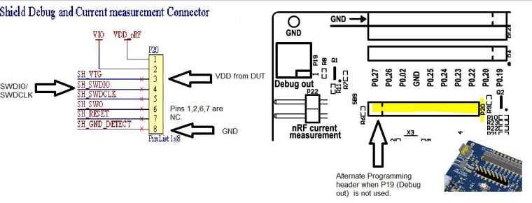
I have nrf52 dk that I tried to use as a programmer but it didn't worked.@Toyman What is the make and model of the module. You can use the nRF52-DK to erase the device. P20 is a ease access to the programming pins on that board. You need to power up the module, run the VDD from the module back to the dev kit , P20, Pin2. Hook up the SWDIO lines to Pin3 and the SWDCLK to Pin4. and Ground, Pin8. As reset is not hardwired you don't have to hook that up unless you want to (Pin7. .  You can use nRFJPROG to exersise the J-Link (Segger). This is found in the downloadable tools on the Nordic site. BTW - I have no problem using J-Link Commander version 6.20c with the nRF52-DK with the nRF52832 mounted. I hope this helped.
-
@NeverDie This may be old news but I will throw it out anyway. The Reset pin on the nRF52 series is both a GPIO and RESET line (one or the other) . This is not a dedicated Reset however and the application must define that pin as RESET. This is the only pin that can be defined as reset. The Datasheet describes this as well.
@Jokgi said in nRF5 Bluetooth action!:
@NeverDie This may be old news but I will throw it out anyway. The Reset pin on the nRF52 series is both a GPIO and RESET line (one or the other) . This is not a dedicated Reset however and the application must define that pin as RESET. This is the only pin that can be defined as reset. The Datasheet describes this as well.
Yes, and thanks to @d00616's work, RESET can also be enabled/disabled from the Tools menu of the arduino IDE if using myNRF5Board as the board definition.
-
I just now compared the transmission range and packet loss of the cheap nRF51822 to the Ebyte nRF52832. I expected that the Ebyte, with its bigger and fancier antenna, to mop the floor with the nRF51822, but I was surprised to find that they actually seem fairly comparable (at least in my informal, off-the-cuff testing). So, if you have a sensor that's mostly transmission oriented, like, say, a TH sensor, the smaller and cheaper nRF51822 is maybe worth considering.
@NeverDie said in nRF5 Bluetooth action!:
the smaller and cheaper nRF51822 is maybe worth considering.
That is interesting. What sort of range where you getting?
Do you have the 840 dev kit? If so, can you measure range on that guy? Should be 10x I would think.
-
@NeverDie said in nRF5 Bluetooth action!:
the smaller and cheaper nRF51822 is maybe worth considering.
That is interesting. What sort of range where you getting?
Do you have the 840 dev kit? If so, can you measure range on that guy? Should be 10x I would think.
Around 30 feet, through some walls, but at 2mbps. I realize that's not very far, but even so the measured packet loss (informal testing) is pretty high at that speed. I can see why most people default to 250kbps instead.
I don't have the 840 dev kit yet, mostly because I don't see anyother 840 modules on the market right now.
-
What's a good initial value to use for DATAWHITEIV, if doing data whitening?
-
@Toyman What is the make and model of the module. You can use the nRF52-DK to erase the device. P20 is a ease access to the programming pins on that board. You need to power up the module, run the VDD from the module back to the dev kit , P20, Pin2. Hook up the SWDIO lines to Pin3 and the SWDCLK to Pin4. and Ground, Pin8. As reset is not hardwired you don't have to hook that up unless you want to (Pin7. .  You can use nRFJPROG to exersise the J-Link (Segger). This is found in the downloadable tools on the Nordic site. BTW - I have no problem using J-Link Commander version 6.20c with the nRF52-DK with the nRF52832 mounted. I hope this helped.
@Jokgi Thanks. That's exactly what I did. Flashed successfully but ideally I'd like to find a way to power the module from the DK (I had to use the external power)
Unfortunately, this was the first time when BMP let me down. It just failed to load either softdevice or the sketch hex while Jlink@DK handled it without any problem. -
@d00616
Which settings are key for ensuring that packets sent by the nRF24 are correctly received by the nRF5? It would be nice to leverage the versions of the nRF24 that have amplified Tx. For sending wake-up packets, I shoudln't need shockburst, and so maybe this will work fairly easily. -
@d00616
Which settings are key for ensuring that packets sent by the nRF24 are correctly received by the nRF5? It would be nice to leverage the versions of the nRF24 that have amplified Tx. For sending wake-up packets, I shoudln't need shockburst, and so maybe this will work fairly easily.@NeverDie said in nRF5 Bluetooth action!:
Which settings are key for ensuring that packets sent by the nRF24 are correctly received by the nRF5? It would be nice to leverage the versions of the nRF24 that have amplified Tx.
These are more than settings. You have to set the Radio configuration like in Radio_ESB.cpp, reverse the addresses and handle sending ACK packages by software.
This is a good resource to understand the OTA protocol: https://hackaday.io/project/11942-antenna-diversity-receive-and-transmit/log/39510-shockburst-vs-enhanced-shockburst-nrf24-vs-nrf5x
I can provide a simple example how to use the MySensors transport code without Radio Head. This works for nRF5 and nRF24 modules, but its outside of that what the MY_CORE_ONLY mode is designed for.
#define MY_CORE_ONLY #ifndef ARDUINO_ARCH_NRF5 #define MY_NODE_ID (1) #define SND_TO (2) #else #define MY_NODE_ID (2) #define SND_TO (1) #endif // Enable debug #define MY_DEBUG //#define MY_DEBUG_VERBOSE_RF24 //#define MY_DEBUG_VERBOSE_NRF5_ESB // RF24_250KBPS RF24_1MBPS RF24_2MBPS #define MY_RF24_DATARATE (RF24_1MBPS) // NRF5_250KBPS NRF5_1MBPS NRF5_2MBPS #define MY_NRF5_ESB_MODE (NRF5_1MBPS) // Enable and select radio type attached #ifndef NRF5 #define MY_RADIO_NRF24 #else #define MY_RADIO_NRF5_ESB #endif #include <MySensors.h> void setup() { Serial.begin(115200); hwInit(); transportInit(); transportSetAddress(MY_NODE_ID); } void loop() { // Check for packages while (transportAvailable()) { uint8_t buffer[256]; uint8_t num = transportReceive(&buffer); Serial.print("Data="); for (int i=0;i<num;i++) { if (buffer[i]<0x10) Serial.print("0"); Serial.print(buffer[i], HEX); Serial.print(" "); } Serial.println(); } wait(1000); // Send data transportSend(SND_TO, "abcdefghijklmnopqrstuvwxyzabcdefghijklmnopqrstuvwxyz",32, false); } -
@Jokgi said in nRF5 Bluetooth action!:
@NeverDie This may be old news but I will throw it out anyway. The Reset pin on the nRF52 series is both a GPIO and RESET line (one or the other) . This is not a dedicated Reset however and the application must define that pin as RESET. This is the only pin that can be defined as reset. The Datasheet describes this as well.
Yes, and thanks to @d00616's work, RESET can also be enabled/disabled from the Tools menu of the arduino IDE if using myNRF5Board as the board definition.
@NeverDie said in nRF5 Bluetooth action!:
Yes, and thanks to @d00616's work, RESET can also be enabled/disabled from the Tools menu of the arduino IDE if using myNRF5Board as the board definition.
The reset support isn't complete at the moment. The menu is active, but it has no effect at the moment. I fix this with release 0.2.0.