Controlling Blinds.com RF Dooya Motors with Arduino and Vera
-
@BulldogLowell I may have to go that route. It will probably be easier and cheaper for me anyway! First I need to finish the rain gauge :)
@CalvinAndHobbes Yes, that would be nice if they had some integration but doubtful. There is a z-wave controller from Leviton (Leviton VRF01-1LZ Vizia RF) but it's over $100 normally. Too much for me.
-
@petewill I looked at the Leviton controller - but I am in Australia, and they don't make an Australian version (for some reason, Z-Wave in Australia is on a different frequency).
And the fans I am using are Hunter Pacific fans made by an Australian company, and that is probably why the remote works on a different frequency. I believe Hunter and Hunter Pacific are different companies - just in case anyone gets them confused. -
I contacted the manufacturer, and they confirmed the protocol is a proprietary one, but they suggested I hack the remote directly, and even offered to send me some remotes to play with, so I am going to go down that route. The remote is very easy to hack too.
-
I have a similar challenge, to automate some fans that I have in my house. I didn't have the same luck when contacting the manufacturer. I tried to hack the radio messages using both 433Mhz and 315Mhz sniffers, but they must use a different radio, or I did something wrong.
It is relatively easy to hack my remotes and insert an Arduino + radio, however I'm thinking in other aspects before start --- Such as replacing the battery of the remote (currently a single CR2032 cell) , as it will have to be "always on" in order to listen to the gateway.
I'm also think in do a 'bi-way' interface, so instead only listem gw and 'press buttons' in the remote, the inserted arduino would also sense if any button is pressed in the remote and report it back to GW.
And my remotes uses the same key for on AND off. So unless I put another sensor nearby (or in) the fans, the gw will never 'be sure' if the fan is on or off...
Just some thoughts about the topic...
Home Assistant / Vera Plus UI7
ESP8266 GW + mySensors 2.3.2
Alexa / Google Home -
I have a similar challenge, to automate some fans that I have in my house. I didn't have the same luck when contacting the manufacturer. I tried to hack the radio messages using both 433Mhz and 315Mhz sniffers, but they must use a different radio, or I did something wrong.
It is relatively easy to hack my remotes and insert an Arduino + radio, however I'm thinking in other aspects before start --- Such as replacing the battery of the remote (currently a single CR2032 cell) , as it will have to be "always on" in order to listen to the gateway.
I'm also think in do a 'bi-way' interface, so instead only listem gw and 'press buttons' in the remote, the inserted arduino would also sense if any button is pressed in the remote and report it back to GW.
And my remotes uses the same key for on AND off. So unless I put another sensor nearby (or in) the fans, the gw will never 'be sure' if the fan is on or off...
Just some thoughts about the topic...
@rvendrame said:
Just some thoughts about the topic...
Thanks. I agree, there doesn't seem to be a perfect solution. For my blinds we rarely use the remotes that came with them. That way we don't need to worry about the status being incorrect. I have modified phones placed around the house we use as control panels as well as apps on our phones. But, for the most part the blinds are all controlled automatically by the light level outside. A ceiling fan would be different though I'd imagine.
-
Hi to everyone! Im very (I mean VERY) new at this, and Im far to be a programer or an specialist, Im just an enthusiastic end user willing to do all of you experts do!
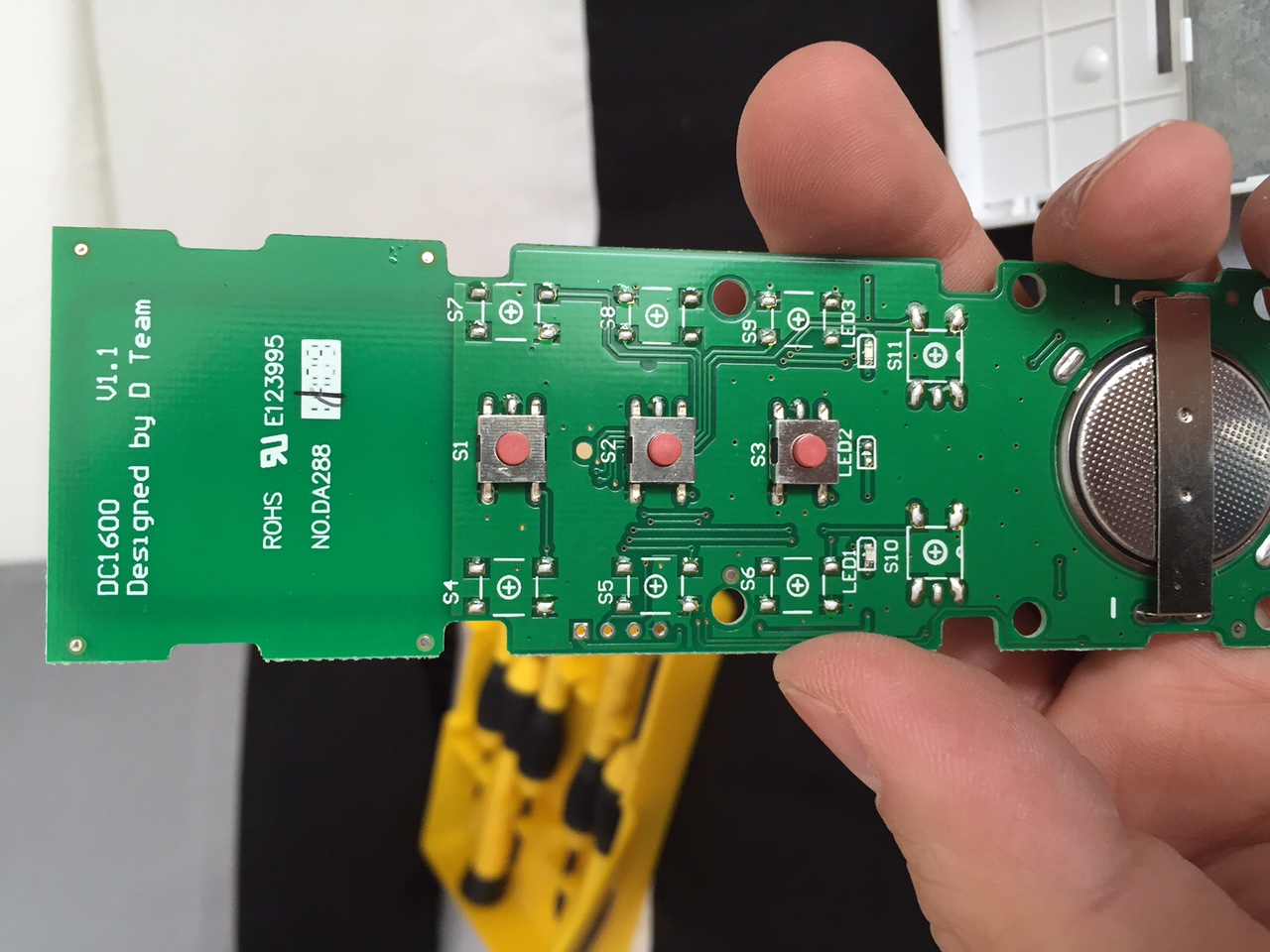
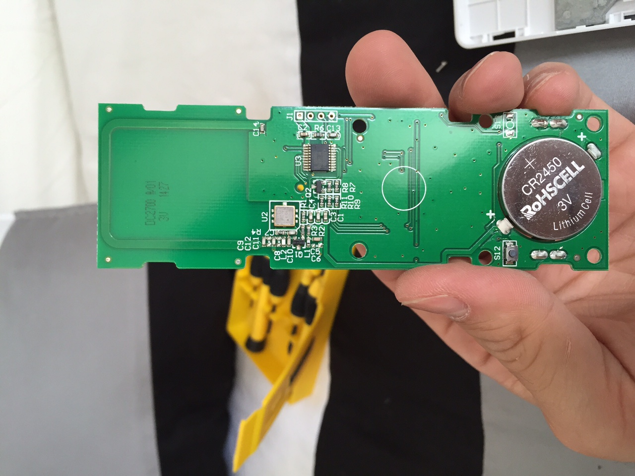
I have the same problem as Pete had, I have some dooya motors in my blinds and I want to integrate them to my smarthome system. This blinds are controlled by a remote control with 3 buttons, up – down – stop, and they are suppose to be RF, they have awesome range btw (see pics).
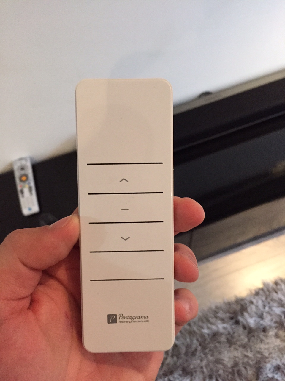
First I tried the RC-Switch to sniff the RF code, but the program return nothing, just blank, that’s why I came to this, wich I would like to thank Pete for giving a light at the end of the tunel! (which Im still in).
I did all the process to sniff the signal of the remotes, and this is what I got and traduced to binary:
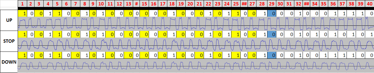
Not the same wave structure (squared) but I hope it has nothing to do.
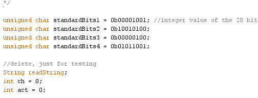
Now Im in the process of testing this code just with the Arduino, but it doesn’t work! I followed the code Pete uploaded and change the highlighted parts with my code, please let me know if I did ok, this are what I changed:
This first part, I used the first 28 bits of my signal, which is the same in the 3 comands:
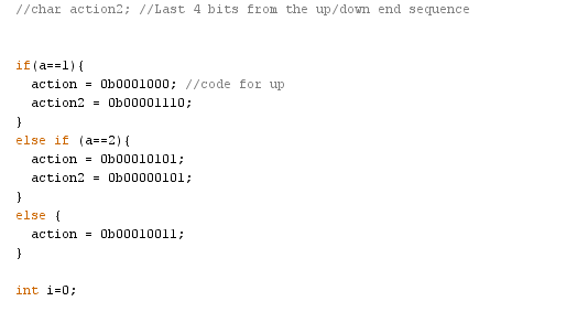
Here, I used the last 8 bits for each comand:
Any clues what I might be doing wrong?
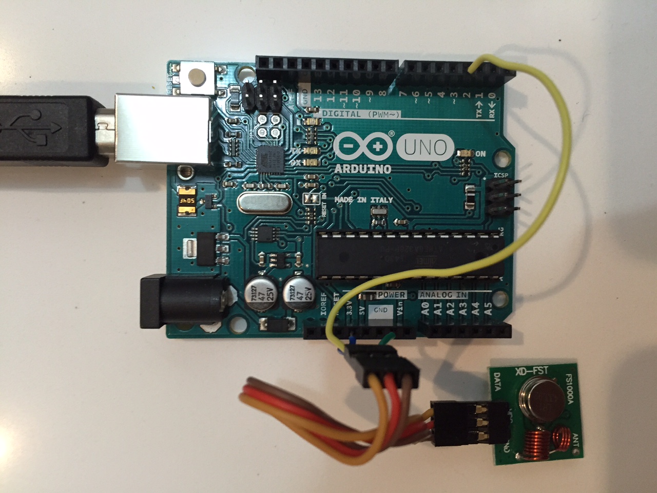
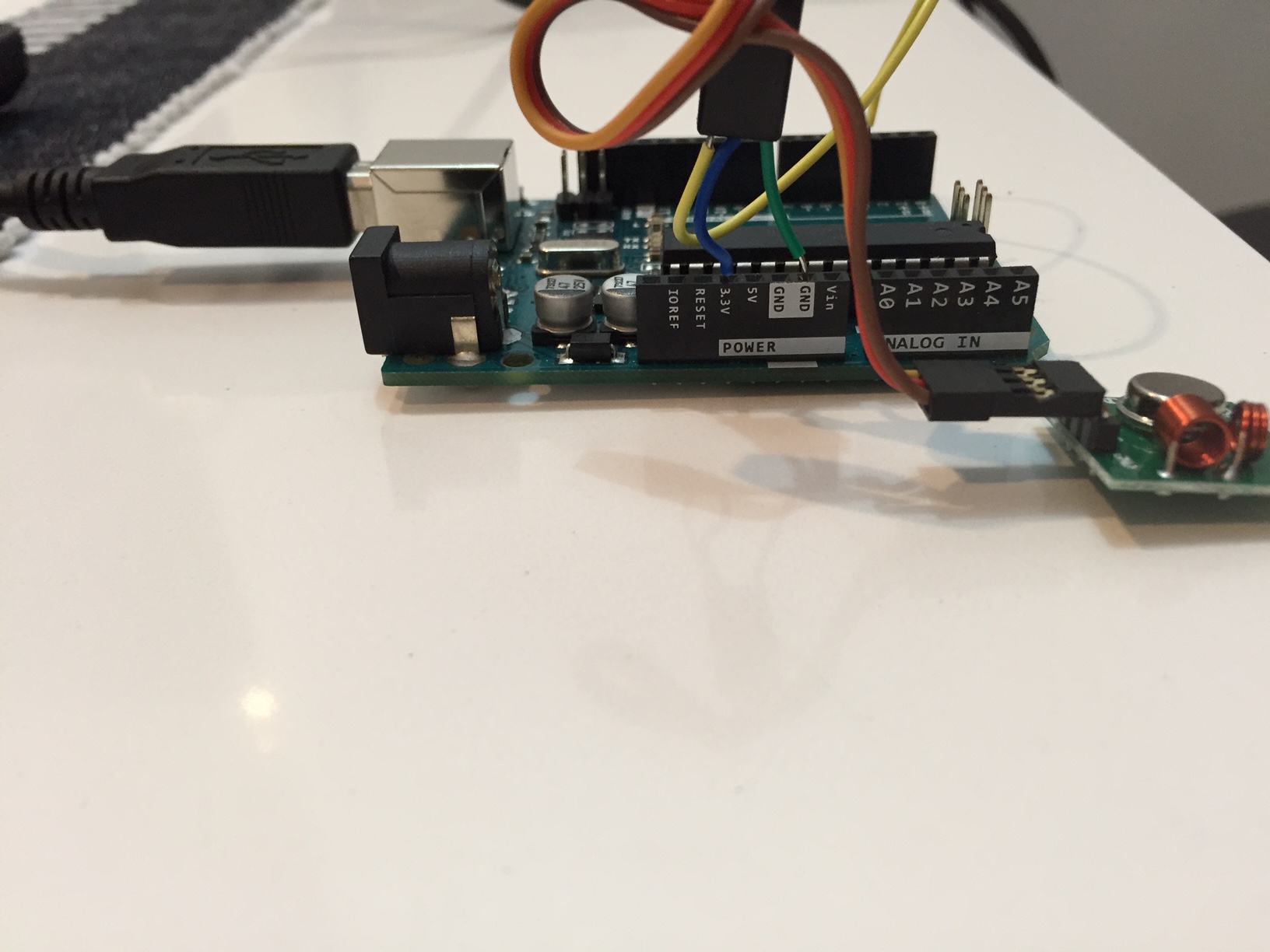
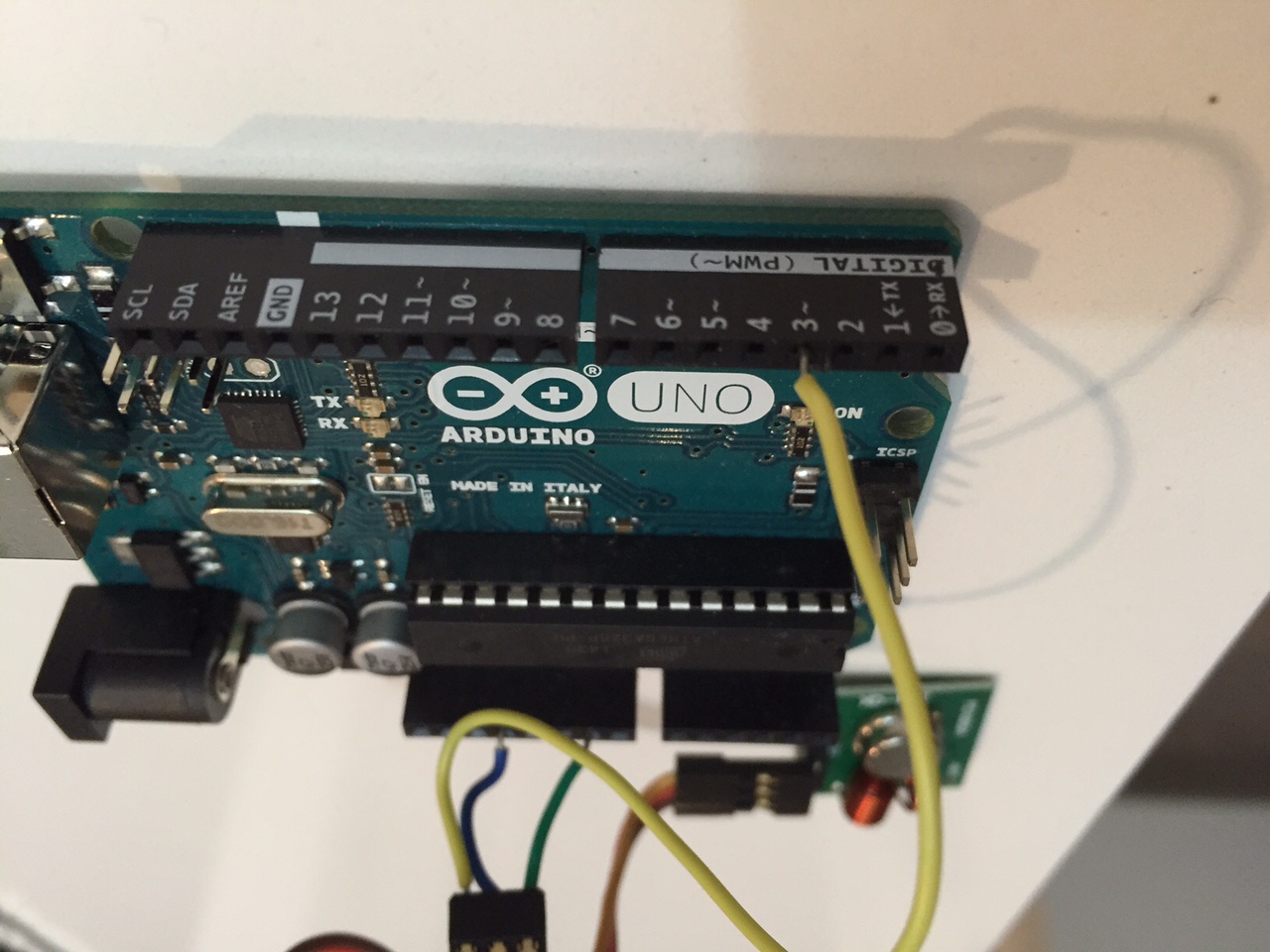
Just in case, Im using an Arduino UNO, and I connected it this way:
Thanks in advance!
-
Hi to everyone! Im very (I mean VERY) new at this, and Im far to be a programer or an specialist, Im just an enthusiastic end user willing to do all of you experts do!
I have the same problem as Pete had, I have some dooya motors in my blinds and I want to integrate them to my smarthome system. This blinds are controlled by a remote control with 3 buttons, up – down – stop, and they are suppose to be RF, they have awesome range btw (see pics).
First I tried the RC-Switch to sniff the RF code, but the program return nothing, just blank, that’s why I came to this, wich I would like to thank Pete for giving a light at the end of the tunel! (which Im still in).
I did all the process to sniff the signal of the remotes, and this is what I got and traduced to binary:
Not the same wave structure (squared) but I hope it has nothing to do.
Now Im in the process of testing this code just with the Arduino, but it doesn’t work! I followed the code Pete uploaded and change the highlighted parts with my code, please let me know if I did ok, this are what I changed:
This first part, I used the first 28 bits of my signal, which is the same in the 3 comands:
Here, I used the last 8 bits for each comand:
Any clues what I might be doing wrong?
Just in case, Im using an Arduino UNO, and I connected it this way:
Thanks in advance!
-
@Dwalt said:
@frantona Could you post your entire sketch? Did you measure the signal timing?
Hi! Thanks for your answer. Nope, I didnt measured the signal timing. I missed it. How should I do it?
I will paste the full code this night when I arrive home, Im using the same one Pete posted few messages back.
Thanks a lot!
@frantona Here is a tutorial on figuring out the timing. Pete's sketch uses the timing (length) for the high and low of both the ones and zeros (lines 35-38).
Have you tried this with the RCSwitch or Remoteswitch libraries? They take all the guesswork out of sniffing signals although they don't work for all transmitters. [Edit: nevermind, i reread your post where you did say you tried RCSwitch].
-
What a great thread, thanks @petewill for all of the info. I can't wait to give this a try.
After reading through all of this, am I correct in assuming that using the slider control (or programming a controller to open the shade to a certain %) has not been achieved?
I was thinking about this a bit, and thought about perhaps using a few cheap magnetic door sensors along the edge of the window at different positions. You could then attach a small neodymium magnet to the back of the bottom edge of the shade that passes by the door sensors. Each of those door sensors could report a value back to the controller, indicating its position (ie 0,25,50,75,100), and if the MySensors node receives a slider value from the controller, you could round to the closest value, and raise/lower the shade until that value is achieved.
I'm a complete MySensors/HA/Vera noob, so please excuse my ignorance if this is a ridiculous solution to a simple issue. :grin: -
What a great thread, thanks @petewill for all of the info. I can't wait to give this a try.
After reading through all of this, am I correct in assuming that using the slider control (or programming a controller to open the shade to a certain %) has not been achieved?
I was thinking about this a bit, and thought about perhaps using a few cheap magnetic door sensors along the edge of the window at different positions. You could then attach a small neodymium magnet to the back of the bottom edge of the shade that passes by the door sensors. Each of those door sensors could report a value back to the controller, indicating its position (ie 0,25,50,75,100), and if the MySensors node receives a slider value from the controller, you could round to the closest value, and raise/lower the shade until that value is achieved.
I'm a complete MySensors/HA/Vera noob, so please excuse my ignorance if this is a ridiculous solution to a simple issue. :grin:@Mike1082 You are correct. Slider control hasn't been achieved. I have thought about doing something like this but I haven't had too much of a need for it in the 1+ years I have had the blinds. Usually up or down is all I want. :)
The one problem I could see with doing this is you will need some sort of device placed at the blind. Currently all you need is power (battery or hard wired) and this works. If you want to report values back, you will need another sensor there. Not a deal breaker but not ideal. Also, you would need a way to confirm that it stopped (in case the signal didn't get received from the blind). If you are seriously considering doing this you may want to look into using a reed switch and mounting it on the spindle that turns when the blinds go up/down. That way you get a cleaner install with more frequent updates.
I'd love to see it if you end up doing it. It would be a fun project!
-
@petewill
Nice work!What kind of battery is powering the blinds.com motor and its receiver? From looking at your video, it appears the blinds.com receiver is constantly listening, and having a receiver constantly listening 24/7 all the time can take quite a lot of power (or, at least it would if it were using an NRF24L01+ or an RFM69, although I of course realize it isn't using either one of those).
Blinds.com says it can take a refillable "wand" that gives 12 volts. So, would that be 8x D-cell batteries?
Do you find that you need to change the battery in the receiver often?
Just trying to get a feel for what it would take to be listening 24/7.
@NeverDie Thanks! It is powered by 8 AA batteries in the battery wand. I actually hardwired mine though. I was able to get power to all my windows fairly easily (although my wife would disagree). So, unfortunately I have no idea how long they last. I feel like I remember people reporting about a year but I can't say where I remember that from.
-
Hi to everyone! Im very (I mean VERY) new at this, and Im far to be a programer or an specialist, Im just an enthusiastic end user willing to do all of you experts do!
I have the same problem as Pete had, I have some dooya motors in my blinds and I want to integrate them to my smarthome system. This blinds are controlled by a remote control with 3 buttons, up – down – stop, and they are suppose to be RF, they have awesome range btw (see pics).
First I tried the RC-Switch to sniff the RF code, but the program return nothing, just blank, that’s why I came to this, wich I would like to thank Pete for giving a light at the end of the tunel! (which Im still in).
I did all the process to sniff the signal of the remotes, and this is what I got and traduced to binary:
Not the same wave structure (squared) but I hope it has nothing to do.
Now Im in the process of testing this code just with the Arduino, but it doesn’t work! I followed the code Pete uploaded and change the highlighted parts with my code, please let me know if I did ok, this are what I changed:
This first part, I used the first 28 bits of my signal, which is the same in the 3 comands:
Here, I used the last 8 bits for each comand:
Any clues what I might be doing wrong?
Just in case, Im using an Arduino UNO, and I connected it this way:
Thanks in advance!
Your code has an error in the 'action' section of the sketch.
if(a==1){
          action = 0b0001000;  //code for up
It is missing a digit or bit. It should read:
if(a==1){
          action = 0b00010001; //code for up
I also think you mixed the 'down' with 'stop' actions. Try this:
if(a==1){ action = 0b00010001; //code for up action2 = 0b00001110; } else if (a==2){ action = 0b00010011; //code for down action2 = 0b00001100; } else if (a==3){ action = 0b00010101; //code for stop action2 = 0b00000101; } -
I hope its ok that I use this thread for my question, because the topic 'kinda fits:
does anyone know a (cheap) way to add a motor (that could be controlled by mysensor) to existing blinds? In theory you would only need a small motor I guess, but I am unsure how to connect that to the blinds.. -
Hello,
there is an other way to control your shutters.
It´s itegrated in FHEM. There are also the decryption at the shuttersignal. All 40 Bit and the explain to the 40 Bit.
sorry for my weak english.
Jarnsen
-
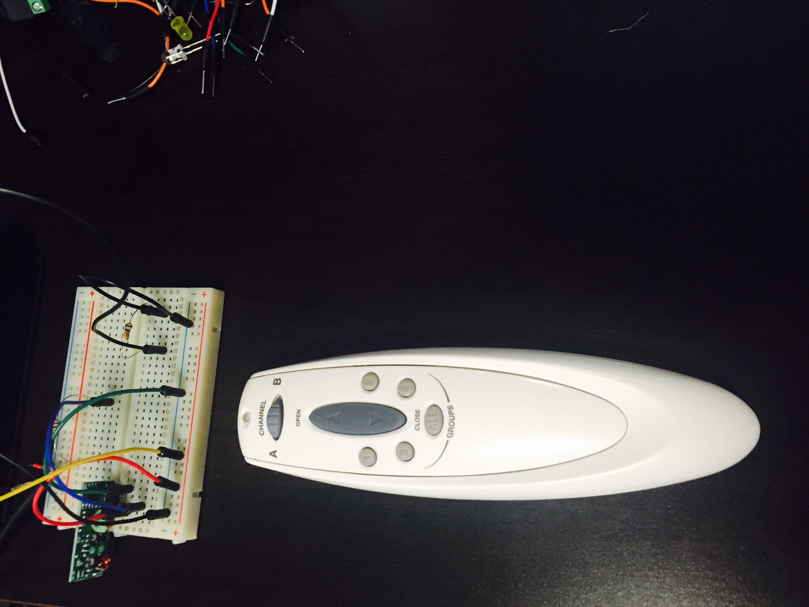
Hi @petewill , I've been trying to implement a similar setup to this for the past few days, however I've unfortunately been unsuccessful with the RF sniffing step. I've tried multiple RF receivers (I have a 10-pk), multiple resistors, and multiple audio cables, yet the feedback from Audacity appears the same whether I'm not doing anything or spamming the remote buttons:
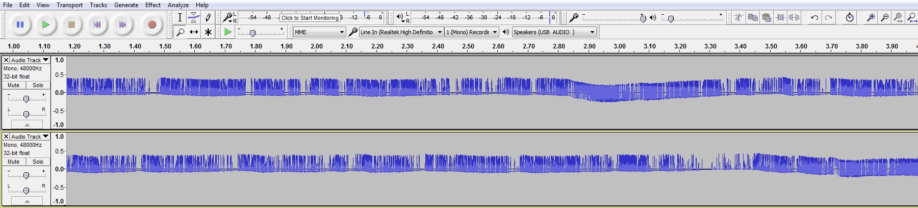
Top is with nothing being pressed, bottom is with hitting buttons on the remote. Might you know of any other possible troubleshooting options I could do? If it helps, below is the remote from blinds.com:
Any advice would be appreciated. Thanks!
-
Hi @petewill , I've been trying to implement a similar setup to this for the past few days, however I've unfortunately been unsuccessful with the RF sniffing step. I've tried multiple RF receivers (I have a 10-pk), multiple resistors, and multiple audio cables, yet the feedback from Audacity appears the same whether I'm not doing anything or spamming the remote buttons:
Top is with nothing being pressed, bottom is with hitting buttons on the remote. Might you know of any other possible troubleshooting options I could do? If it helps, below is the remote from blinds.com:
Any advice would be appreciated. Thanks!
@Rantlers Sorry for the delayed reply... busy day back at work.
Hmm. Did you zoom in on the audacity waveform? I had to zoom way in. If that doesn't show anything it may be that the remotes are at a different frequency now. That looks different than mine. Is there any indication which frequency the remote is on?
Also, I was able to actually hear the signal on my speakers when I played it back. It sounded like high pitched digital noise. Do you hear anything like that?
My "How To" home automation video channel: https://www.youtube.com/channel/UCq_Evyh5PQALx4m4CQuxqkA