RFM69HW 433 communication problem
-
I'm using the mock sensors sketch. The node just doesn't get any reply. I'll try with the 17cm wire antenna.
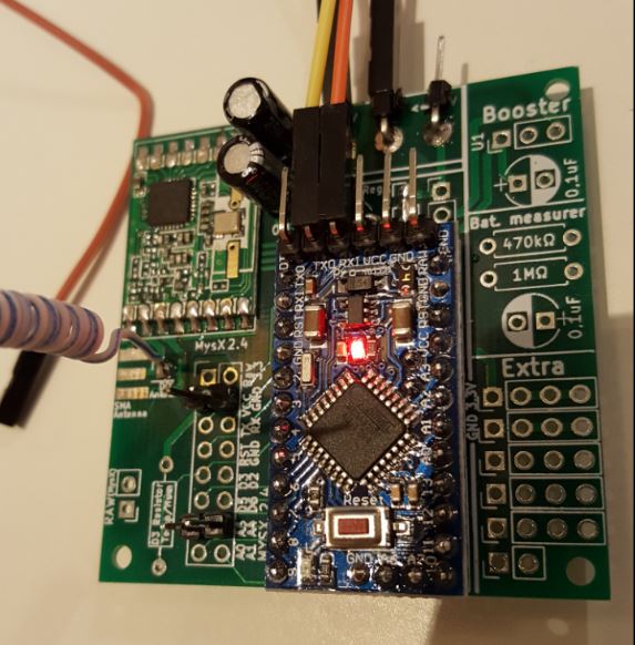
@gohan - I have made a second node to test the DIY antenna.
It works good (on my bench, have not tested range) as you can see in my logs.Im running MySensors dev (not the latest... but updated a couple of weeks ago) with a Serial RFM69 GW (both node and GW are build on EasyPCB.
I tried both 3.3v regulated and 5v with a voltage regulator.
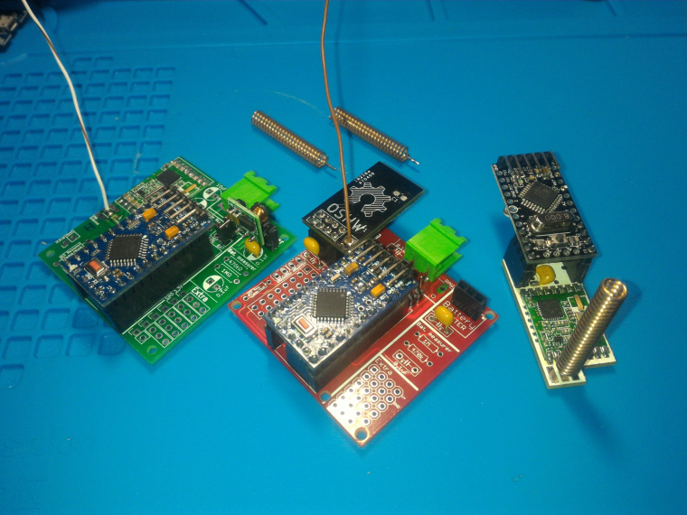
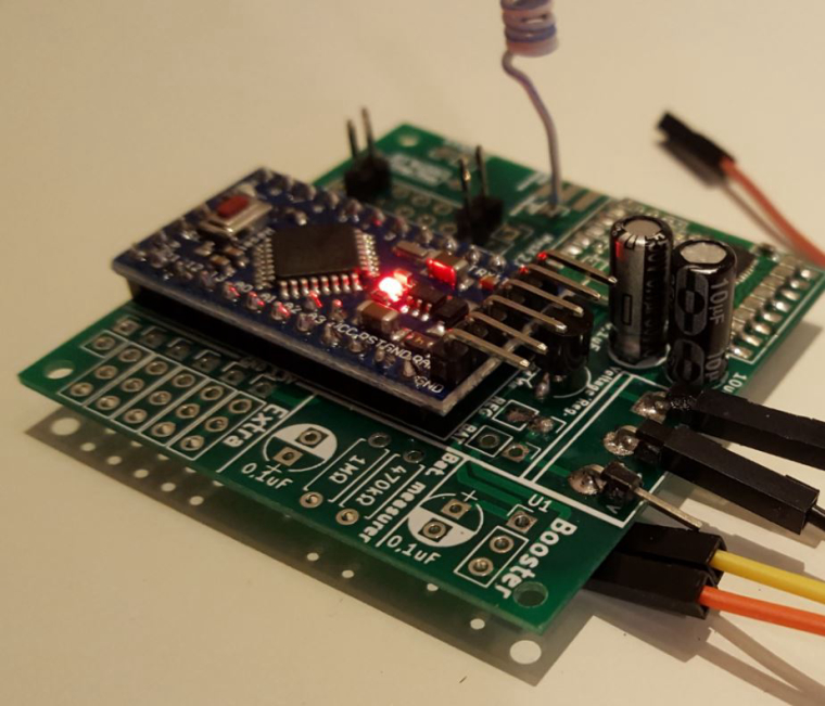
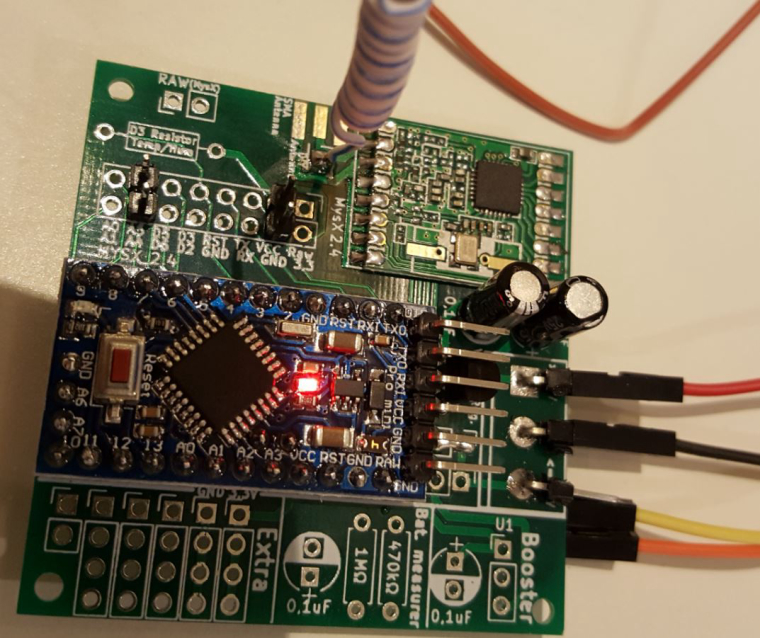
Here are some images if my build... I hope they can give you some ideas.
(REG are shorted due to I used 3.3 regulated voltage as well - this does not affect anything using 5v).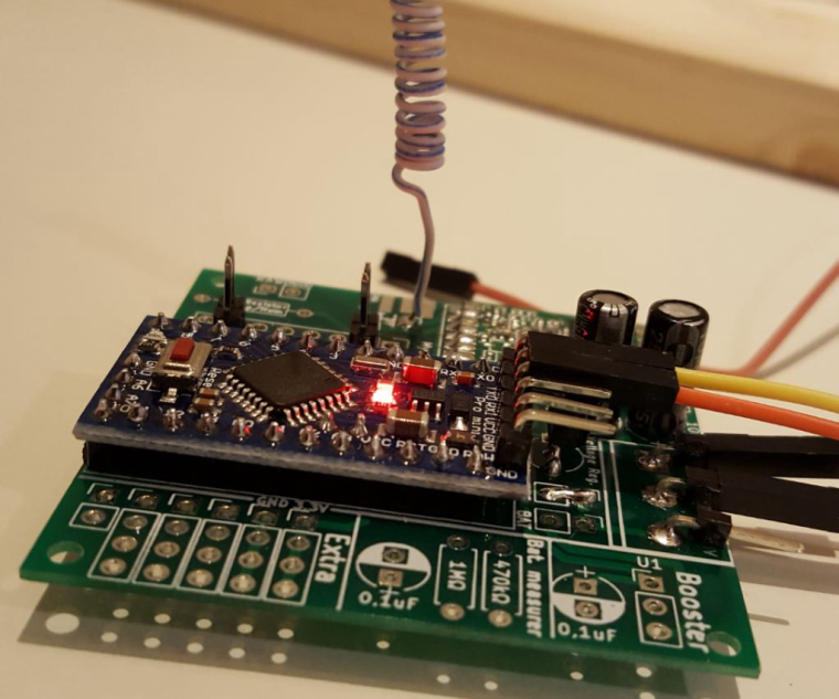
I would suggest you do a continuity test from all the pins to the right pins on the pro mini, just to make sure they are connected. It is not that easy to solder the SMD pads on the RFM radio as the pins on the Nrf24l01+. You cant tell if they are ok since they are not visible all the way because of the module. First thing that happened was that the radio would not initialise, and I had to "re-flow", heat the pads up again so everything connected. It was not visible and impossible to see the bad connection.
I would also measure voltage over all important parts. Also make sure you do a continuity test from the top of your antenna to the ANT on the RFM module.
-
I did continuity check on all pins and antenna, everything seems fine. It seems there is something on the nodes that can't receive or the gateway can't send
@gohan - ok... strange!
As I mentioned in PM, I use the W and not HW version... i dont know if thats the case, but let me order some HW modules and I will check!Could you upload a picture of your hardware? Maybe I can spot something?
-
@gohan - ok... strange!
As I mentioned in PM, I use the W and not HW version... i dont know if thats the case, but let me order some HW modules and I will check!Could you upload a picture of your hardware? Maybe I can spot something?
This post is deleted! -
Do you get the same log on all boards? They are initialised but then...? No reply or NACK?
I would use the board with the least connections for GW and power the GW with a rock solid 3.3v.
With the GW i would use the SMA connector with a bought antenna to be sure... -
Yes, they all get no reply.
I don't have the SMA nor the right antenna at the moment.
I am also using one of those MB102 for 3.3v supply, but nothing changes. I'll try with a beefier voltage regulator@gohan said in RFM69HW 433 communication problem:
MB102
Should be enough... a really though one this!
My bet would be the antennas though... and the GW antenna is offcource the most important. I would focus on that (without I can promise that is the problem). -
I got the new batch of 4 new rfm69h but I am still getting no communication between gw and node, now I can't even get some messages received from gw. I have updates to latest development library and used pretty much all defaults values besides setting the right frequency. Unless I'm doing something really wrong, there must be something wrong in the basics. I'll have to try some more combinations with the antennas, but I am really starting to get discouraged since the nrf24 worked fine since the beginning.
-
I got the new batch of 4 new rfm69h but I am still getting no communication between gw and node, now I can't even get some messages received from gw. I have updates to latest development library and used pretty much all defaults values besides setting the right frequency. Unless I'm doing something really wrong, there must be something wrong in the basics. I'll have to try some more combinations with the antennas, but I am really starting to get discouraged since the nrf24 worked fine since the beginning.
@gohan - If you have 3.3v on the radio and the arduino, are sure about the software/sketch then I would also suggest trying different antennas. What are you using today? I would buy a SMA connector and a good antenna. Even though I have the DIY antenna on the test-node above, I still have a factory antenna + SMA connector on the gw.
-
I'm not very familiar with that hardware, but from a cursory glance it looks like you don't have the interrupt pin connected? Unlike the NRF modules, the RFM69s are interrupt-driven and need DIO0 connected to pin 2
@Carywin - its EasyPCB RFM edition and D2 is connected to DIO0 pin as described in the radio tutorial so unless he is using a strange RFM module with the interrupt pin on some different place that should work.
-
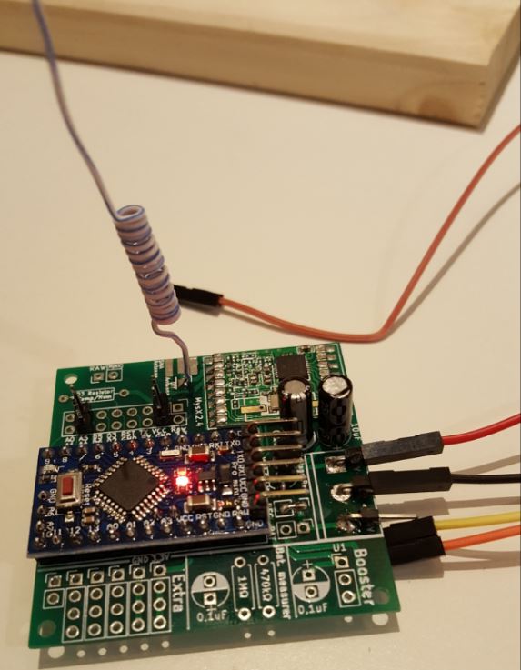
Right, I'm sure that node is fine, I mainly just zoomed in and looked at this one:
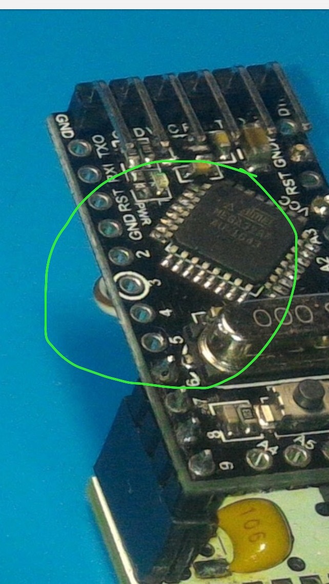
I use this same small piggyback board for many nodes and it works great with those 21mm coil antennas.However, I just noticed the #define for TX power. I think the H and HW versions have a minimum of 13dB or something. Have you tried without?
-
I tried the coiled wire like the one you are using, it didn't change at all. I am running out of options unless there is a problem with the rfm modules.
-
Right, I'm sure that node is fine, I mainly just zoomed in and looked at this one:
I use this same small piggyback board for many nodes and it works great with those 21mm coil antennas.However, I just noticed the #define for TX power. I think the H and HW versions have a minimum of 13dB or something. Have you tried without?
-
@Carywin I was using the nodes on easypcb also for the new ones. What do you suggest I set the TX power?
@gohan - i never messed with TX power... have a look and try my sketches above. They work for me.
-
I would suggest comment out the TX power setting and let the ATC control it. If it still doesn't work, try:
#define MY_RFM69_ATC_MODE_DISABLED
#define MY_RFM69_TX_POWER_DBM 20
Edit:
Maybe also try#define MY_DEBUG_VERBOSE_RFM69and see if that tells you anything more.