
ds18b20 and negative temperature values
-
hi,
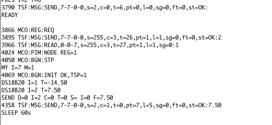
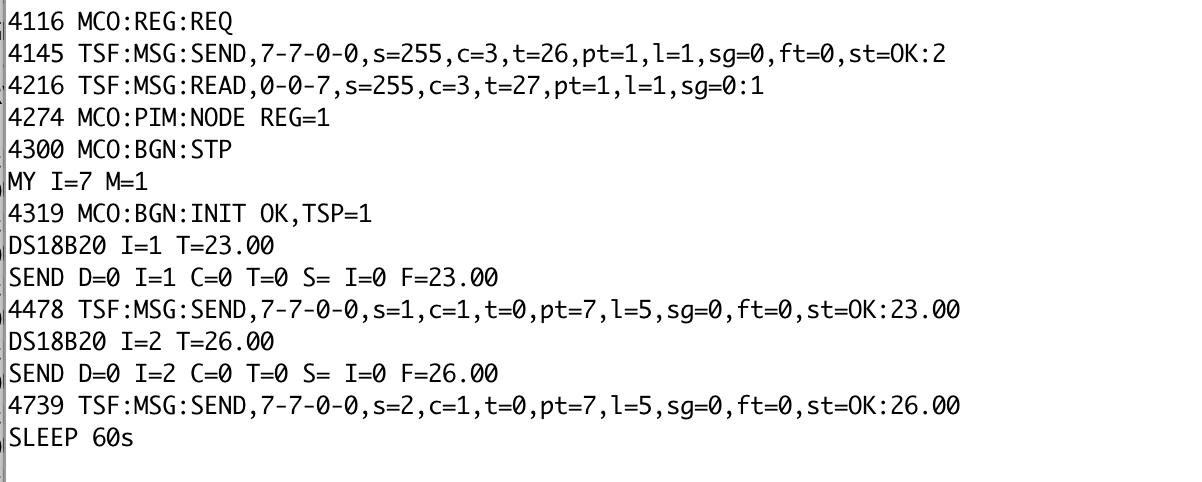
I'm having problems with negative temperatures on a node with 2 ds18b20
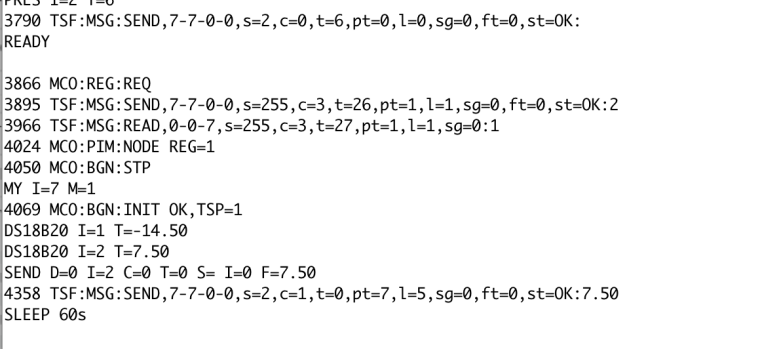
if both sensors measure the positive temperature, the values are correctly sent. If one of the 2 negative negative values is ignored.
everything works correctly using the example in the library.both positive values
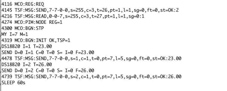
One Negative value
-
Config.h
#ifndef config_h
#define config_h

/**********************************
 * Sketch configuration
 */

#define SKETCH_NAME "Temperatura"
#define SKETCH_VERSION "1.0"

/**********************************
 * MySensors node configuration
 */

// General settings
#define MY_BAUD_RATE 9600
#define MY_DEBUG
//#define MY_NODE_ID 100
//#define MY_SMART_SLEEP_WAIT_DURATION_MS 500

// NRF24 radio settings
#define MY_RADIO_NRF24
//#define MY_RF24_ENABLE_ENCRYPTION
//#define MY_RF24_CHANNEL 76
//#define MY_RF24_PA_LEVEL RF24_PA_HIGH
//#define MY_DEBUG_VERBOSE_RF24
//#define MY_RF24_DATARATE RF24_250KBPS

// RFM69 radio settings
//#define MY_RADIO_RFM69
//#define MY_RFM69_FREQUENCY RF69_868MHZ
//#define MY_RFM69_FREQUENCY RFM69_868MHZ
//#define MY_IS_RFM69HW
//#define MY_RFM69_NEW_DRIVER
//#define MY_RFM69_ENABLE_ENCRYPTION
//#define MY_RFM69_NETWORKID 100
//#define MY_DEBUG_VERBOSE_RFM69
//#define MY_RF69_IRQ_PIN D1
//#define MY_RF69_IRQ_NUM MY_RF69_IRQ_PIN
//#define MY_RF69_SPI_CS D2
//#define MY_RFM69_ATC_MODE_DISABLED

// RS485 serial transport settings
//#define MY_RS485
//#define MY_RS485_BAUD_RATE 9600
//#define MY_RS485_DE_PIN 2
//#define MY_RS485_MAX_MESSAGE_LENGTH 40
//#define MY_RS485_HWSERIAL Serial1

// Message signing settings
//#define MY_SIGNING_SOFT
//#define MY_SIGNING_SOFT_RANDOMSEED_PIN 7
//#define MY_SIGNING_REQUEST_SIGNATURES
//#define MY_SIGNING_ATSHA204

// OTA Firmware update settings
//#define MY_OTA_FIRMWARE_FEATURE
//#define OTA_WAIT_PERIOD 300
//#define FIRMWARE_MAX_REQUESTS 2
//#define MY_OTA_RETRY 2

/**********************************
 * MySensors gateway configuration
 */
// Common gateway settings
//#define MY_REPEATER_FEATURE

// Serial gateway settings
//#define MY_GATEWAY_SERIAL

// Ethernet gateway settings
//#define MY_GATEWAY_W5100

// ESP8266 gateway settings
//#define MY_GATEWAY_ESP8266
//#define MY_ESP8266_SSID ""
//#define MY_ESP8266_PASSWORD ""

// Gateway networking settings
//#define MY_IP_ADDRESS 192,168,178,87
//#define MY_IP_GATEWAY_ADDRESS 192,168,178,1
//#define MY_IP_SUBNET_ADDRESS 255,255,255,0
//#define MY_PORT 5003
//#define MY_GATEWAY_MAX_CLIENTS 2
//#define MY_USE_UDP

// Gateway MQTT settings
//#define MY_GATEWAY_MQTT_CLIENT
//#define MY_CONTROLLER_IP_ADDRESS 192, 168, 178, 68
//#define MY_PORT 1883
//#define MY_MQTT_USER "username"
//#define MY_MQTT_PASSWORD "password"
//#define MY_MQTT_CLIENT_ID "mysensors-1"
//#define MY_MQTT_PUBLISH_TOPIC_PREFIX "mygateway1-out"
//#define MY_MQTT_SUBSCRIBE_TOPIC_PREFIX "mygateway1-in"

// Gateway inclusion mode
//#define MY_INCLUSION_MODE_FEATURE
//#define MY_INCLUSION_BUTTON_FEATURE
//#define MY_INCLUSION_MODE_DURATION 60
//#define MY_DEFAULT_LED_BLINK_PERIOD 300

// Gateway Leds settings
//#define MY_DEFAULT_ERR_LED_PIN 4
//#define MY_DEFAULT_RX_LED_PIN  5
//#define MY_DEFAULT_TX_LED_PIN  6

/***********************************
 * NodeManager configuration
 */

// if enabled, enable debug messages on serial port
#define DEBUG 1

// if enabled, enable the capability to power on sensors with the arduino's pins to save battery while sleeping
#define POWER_MANAGER 1
// if enabled, will load the battery manager library to allow the battery level to be reported automatically or on demand
#define BATTERY_MANAGER 1
// if enabled, allow modifying the configuration remotely by interacting with the configuration child id
#define REMOTE_CONFIGURATION 1
// if enabled, persist the remote configuration settings on EEPROM
#define PERSIST 0
// if enabled, a battery sensor will be created at BATTERY_CHILD_ID (201 by default) and will report vcc voltage together with the battery level percentage
#define BATTERY_SENSOR 1
// if enabled, a signal sensor will be created at RSSI_CHILD_ID (202 by default) and will report the signal quality of the transport layer
#define SIGNAL_SENSOR 0
// if enabled, send a SLEEPING and AWAKE service messages just before entering and just after leaving a sleep cycle and STARTED when starting/rebooting
#define SERVICE_MESSAGES 0

// Enable this module to use one of the following sensors: SENSOR_ANALOG_INPUT, SENSOR_LDR, SENSOR_THERMISTOR, SENSOR_ML8511, SENSOR_ACS712, SENSOR_RAIN, SENSOR_SOIL_MOISTURE
#define MODULE_ANALOG_INPUT 0
// Enable this module to use one of the following sensors: SENSOR_DIGITAL_INPUT
#define MODULE_DIGITAL_INPUT 0
// Enable this module to use one of the following sensors: SENSOR_DIGITAL_OUTPUT, SENSOR_RELAY, SENSOR_LATCHING_RELAY
#define MODULE_DIGITAL_OUTPUT 0
// Enable this module to use one of the following sensors: SENSOR_DHT11, SENSOR_DHT22
#define MODULE_DHT 0
// Enable this module to use one of the following sensors: SENSOR_SHT21, SENSOR_HTU21D
#define MODULE_SHT21 0
// Enable this module to use one of the following sensors: SENSOR_SWITCH, SENSOR_DOOR, SENSOR_MOTION
#define MODULE_SWITCH 0
// Enable this module to use one of the following sensors: SENSOR_DS18B20
#define MODULE_DS18B20 1
// Enable this module to use one of the following sensors: SENSOR_BH1750
#define MODULE_BH1750 0
// Enable this module to use one of the following sensors: SENSOR_MLX90614
#define MODULE_MLX90614 0
// Enable this module to use one of the following sensors: SENSOR_BME280
#define MODULE_BME280 0
// Enable this module to use one of the following sensors: SENSOR_SONOFF
#define MODULE_SONOFF 0
// Enable this module to use one of the following sensors: SENSOR_BMP085
#define MODULE_BMP085 0
// Enable this module to use one of the following sensors: SENSOR_HCSR04
#define MODULE_HCSR04 0
// Enable this module to use one of the following sensors: SENSOR_MCP9808
#define MODULE_MCP9808 0
// Enable this module to use one of the following sensors: SENSOR_MQ
#define MODULE_MQ 0
// Enable this module to use one of the following sensors: SENSOR_MHZ19
#define MODULE_MHZ19 0
// Enable this module to use one of the following sensors: SENSOR_AM2320
#define MODULE_AM2320 0
// Enable this module to use one of the following sensors: SENSOR_TSL2561
#define MODULE_TSL2561 0
// Enable this module to use one of the following sensors: SENSOR_PT100
#define MODULE_PT100 0
// Enable this module to use one of the following sensors: SENSOR_BMP280
#define MODULE_BMP280 0
// Enable this module to use one of the following sensors: SENSOR_DIMMER
#define MODULE_DIMMER 0
// Enable this module to use one of the following sensors: SENSOR_RAIN_GAUGE, SENSOR_POWER_METER, SENSOR_WATER_METER
#define MODULE_PULSE_METER 0

#endif
File
/* NodeManager is intended to take care on your behalf of all those common tasks a MySensors node has to accomplish, speeding up the development cycle of your projects. NodeManager includes the following main components: - Sleep manager: allows managing automatically the complexity behind battery-powered sensors spending most of their time sleeping - Power manager: allows powering on your sensors only while the node is awake - Battery manager: provides common functionalities to read and report the battery level - Remote configuration: allows configuring remotely the node without the need to have physical access to it - Built-in personalities: for the most common sensors, provide embedded code so to allow their configuration with a single line Documentation available on: https://github.com/mysensors/NodeManager */ // load user settings #include "config.h" // include supporting libraries #ifdef MY_GATEWAY_ESP8266 #include <ESP8266WiFi.h> #endif // load MySensors library #include <MySensors.h> // load NodeManager library #include "NodeManager.h" // create a NodeManager instance NodeManager nodeManager; // before void before() { // setup the serial port baud rate Serial.begin(MY_BAUD_RATE); nodeManager.registerSensor(SENSOR_DS18B20, 3); nodeManager.setBatteryMin(1.8); nodeManager.setBatteryMin(3.2); nodeManager.setSleepMinutes(1); /* Register below your sensors */ /* Register above your sensors */ nodeManager.before(); } // presentation void presentation() { // call NodeManager presentation routine nodeManager.presentation(); } // setup void setup() { // call NodeManager setup routine nodeManager.setup(); } // loop void loop() { // call NodeManager loop routine nodeManager.loop(); } // receive void receive(const MyMessage &message) { // call NodeManager receive routine nodeManager.receive(message); } // receiveTime void receiveTime(unsigned long ts) { // call NodeManager receiveTime routine nodeManager.receiveTime(ts); } -
I solved the problem.
The error is in the NodeManager.cpp file in the section below here calculates the average of the detected values.
Exactly at this point// process a float value else if (_value_type == TYPE_FLOAT && total > -1)the program does not send data if the average of the measurements is less than -1.
Certainly a lapse.
The average reading of a temperature sensor may also be negative.
Removed control> -1 and the negative reads sell sent.
It is necessary to analyze the behavior of the program when a sensor does not work, generating as -127 reading. I did not see if the library already does this check. -
Sorry for the delayed answer! Referencing https://github.com/mysensors/NodeManager/issues/219 to follow the resolution which as I mentioned might be a bit more complex unfortunately :)


Hello! It looks like you're interested in this conversation, but you don't have an account yet.
Getting fed up of having to scroll through the same posts each visit? When you register for an account, you'll always come back to exactly where you were before, and choose to be notified of new replies (either via email, or push notification). You'll also be able to save bookmarks and upvote posts to show your appreciation to other community members.
With your input, this post could be even better 💗
Register Login