What did you build today (Pictures) ?

-
@rozpruwacz I try to avoid filled copper areas, which could act as RF blockers. as I mentioned, everything is still in progress, in-wall tests will just come. hopefully I'll have time for that in the next 2 weeks.
I know that this is not the right place to ask but I'm very curious how do you overcome the fact that in EU there's only the live with in the walls for light switches. I saw that you used a HLK-PM0xx module for testing which needs both live and null. Or maybe your "in-wall" wiring is different... Anyways congratulations for your work so far.
-
I know that this is not the right place to ask but I'm very curious how do you overcome the fact that in EU there's only the live with in the walls for light switches. I saw that you used a HLK-PM0xx module for testing which needs both live and null. Or maybe your "in-wall" wiring is different... Anyways congratulations for your work so far.
@mtiutiu well, that's the dirty hacking part :) electricians will probably not like it.
so, for first, I've a different approach to control my lamps compared to other in-wall switches and dimmers, due to the fact, that I won't switch the mains directly, with the switch. I have LED ceiling lamps which operate at 12V, but the power supplies (230V to 12V) are in the lamps' body. it could be possible to switch their mains on/off thus to turn the lamps on/off (this is what I do now with standard switches), but it is not possible to dim the lights this way.
to be able to dim the LEDs as well I'll have a lamp controller node right after the switching PSUs in each lamp. this will be controlled with the in-wall switches (and could be controlled with other nodes/gateways as well), over the air only.as all of my wall lamp switch have dual wiring (one line in, two switched line out) I planned the following setup:
one switched line will be "re-assigned" and wired to N at the lamp. this way, at the wall switch I'll have both L and N. the other switched in-wall line will still forward the L to the lamp, but it will do it directly, to continuously operate the lamp's PSU, which also powers the lamp's controller module.
the controller will be always on and it will control both the dimming (PWM on the 12V) and the switching wich basically allowing or disabling the 12V from the PSU to the LEDs.the in-wall switch will be basically just a radio remote controller this way, but operating from the mains, without any need of batteries.
I hope that my explanation wasn't too complicated :)
-
well today finally i decide to change to c.h.i.p. as a controller with domoticz an amazing device but too bad for the product that got really bad customer support, ( if you planning to buy a c.h.i.p. read the forum first to get all the problems)
this is my controller using a chip, arduino nano
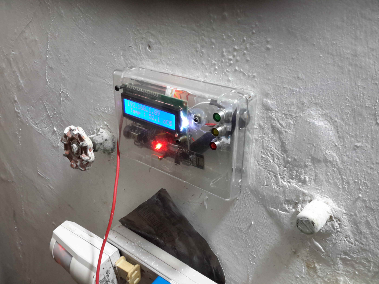
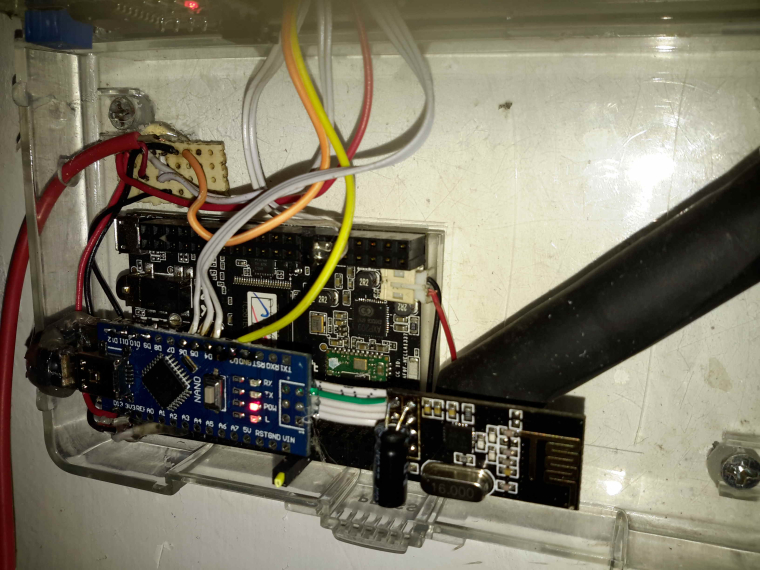
planing to chage the nano to a nodemcu
-
well today finally i decide to change to c.h.i.p. as a controller with domoticz an amazing device but too bad for the product that got really bad customer support, ( if you planning to buy a c.h.i.p. read the forum first to get all the problems)
this is my controller using a chip, arduino nano
planing to chage the nano to a nodemcu
@fernando-alvarez-buylla Is the C.H.I.P. better than a Raspberry Pi Zero? At least with a Pi, you know there's going to be support.
https://www.adafruit.com/product/2885?gclid=EAIaIQobChMIrMm-lcv-1wIVxSSBCh1PJQB3EAQYASABEgItsvD_BwE
https://www.adafruit.com/product/3400 -
@fernando-alvarez-buylla Is the C.H.I.P. better than a Raspberry Pi Zero? At least with a Pi, you know there's going to be support.
https://www.adafruit.com/product/2885?gclid=EAIaIQobChMIrMm-lcv-1wIVxSSBCh1PJQB3EAQYASABEgItsvD_BwE
https://www.adafruit.com/product/3400@neverdie go for the pi zero chip is really nice a little better than the pi zero wifi and bt integraded 4gb and a few cool stuff , but theres people that pay a year ago and still waiting for the chip to arrive , no reply and no support on forum , to me chip is dying , you cant never go wrong with a pi , but i will try in a few months the omega2 to remplace my chips
-
@neverdie go for the pi zero chip is really nice a little better than the pi zero wifi and bt integraded 4gb and a few cool stuff , but theres people that pay a year ago and still waiting for the chip to arrive , no reply and no support on forum , to me chip is dying , you cant never go wrong with a pi , but i will try in a few months the omega2 to remplace my chips
@fernando-alvarez-buylla said in What did you build today (Pictures) ?:
i will try in a few months the omega2 to remplace my chips
What kind of controller are you going to run on that underpowered thing ? Entry level price is cheap but if you want SD card reader and a bit more storage (32Mb) you have to pay 20$, more than the price of an orange pi zero + box which is already available and runs well with Armbian.
-
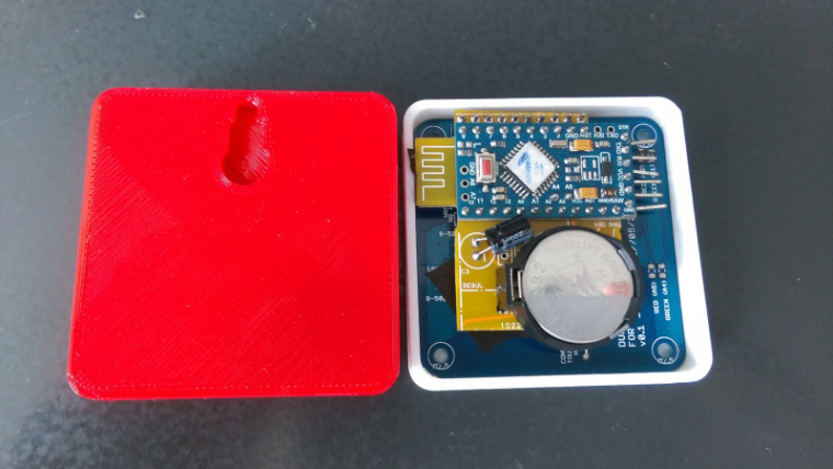
Working on clearing up the backlog of unfinished NModule shields, today I finished to test the dual touch button shield, made a script to use it as on/off button or as dual button with short press = on and long press = off, as seen below as a dual scene controller.
https://www.youtube.com/watch?v=064Jlx2eawII made a box so it can be easily customized depending on what you use it for. Unfortunately internet is too bad at the moment in Vietnam to use Fusion 360 so I made it with 123D Design which is less convenient and it's not really high-end assembly :D
-
Working on clearing up the backlog of unfinished NModule shields, today I finished to test the dual touch button shield, made a script to use it as on/off button or as dual button with short press = on and long press = off, as seen below as a dual scene controller.
https://www.youtube.com/watch?v=064Jlx2eawII made a box so it can be easily customized depending on what you use it for. Unfortunately internet is too bad at the moment in Vietnam to use Fusion 360 so I made it with 123D Design which is less convenient and it's not really high-end assembly :D
@nca78 said in What did you build today (Pictures) ?:
I made a box so it can be easily customized depending on what you use it for.
Is it a 3D printed enclosure then, or did you find some other way to make it? Looks very nice.
-
@nca78 said in What did you build today (Pictures) ?:
I made a box so it can be easily customized depending on what you use it for.
Is it a 3D printed enclosure then, or did you find some other way to make it? Looks very nice.
@neverdie said in What did you build today (Pictures) ?:
@nca78 said in What did you build today (Pictures) ?:
I made a box so it can be easily customized depending on what you use it for.
Is it a 3D printed enclosure then, or did you find some other way to make it? Looks very nice.
3D printed. Bottom of prints can look pretty good if find the good settings and print on a glass surface.
-
Working on clearing up the backlog of unfinished NModule shields, today I finished to test the dual touch button shield, made a script to use it as on/off button or as dual button with short press = on and long press = off, as seen below as a dual scene controller.
https://www.youtube.com/watch?v=064Jlx2eawII made a box so it can be easily customized depending on what you use it for. Unfortunately internet is too bad at the moment in Vietnam to use Fusion 360 so I made it with 123D Design which is less convenient and it's not really high-end assembly :D
-
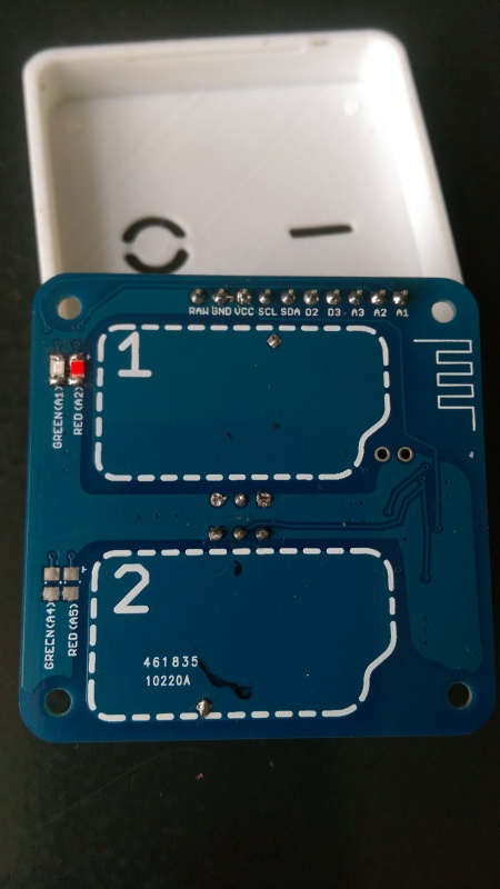
@nca78 I would assume that pads 1 and 2 are capacitive touch surfaces, correct? very nice design.
@dbemowsk said in What did you build today (Pictures) ?:
@nca78 I would assume that pads 1 and 2 are capacitive touch surfaces, correct? very nice design.
Thank you !
Yes using dirt cheap TTP223 breakouts at the back so no SMD soldering needed. -
I received the next version of the leak detector PCB today. Putting it together, it checks out: thanks to a change in layout, it has the same board size as before, but now no clearance issues. i.e. No need for Kapton tape!
If I had had my own PCB CNC etcher, it would have saved me the time I lost waiting for the earlier version from the fab, only to find out that the clearances were too tight and that I would have to re-do it. Looking forward to not having such delays ever again. -
Christmas wreathe for the techie in all of us.
pretty colors
flashing
wire wrappingUses a pro mini and a lot of wire-wrapping. Other components on the circuit boards are just there for show.
(ugh, google photos links not showing up so converted to links)
-
Christmas wreathe for the techie in all of us.
pretty colors
flashing
wire wrappingUses a pro mini and a lot of wire-wrapping. Other components on the circuit boards are just there for show.
(ugh, google photos links not showing up so converted to links)
-
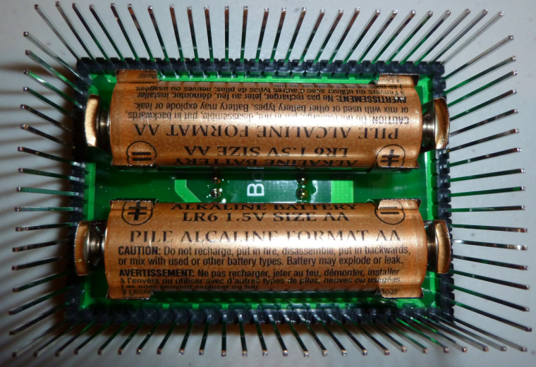
Finally got the PCBs from AllPCB.com (cost 5 Euros and took a total of 7 days from order submission to free DHL delivery to Europe!!!) for my own MySensors Arduino Pro Mini prototyping board. Unfortunately the soldering iron broke during my assembly, so it's not fully finished and I couldn't test it yet, either...

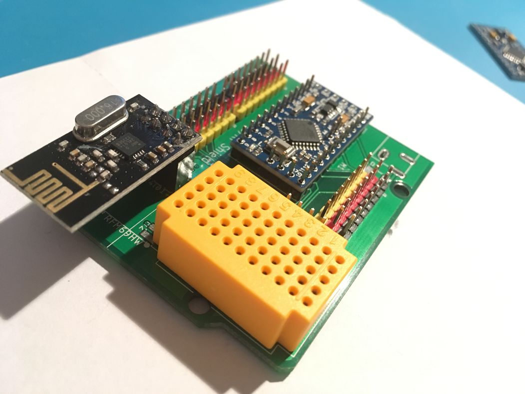
This board is inspired by the Nano IO shields that are offered on AliExpress and improves it further for my needs (and switched to the Pro Mini instead of the Nano).
- Each analog and digital pin of the Pro Mini has its own VCC and GND pins,
- the board also provides its own voltage regulator, solder pins for by NRF24L01+ and RFM69H are provided (plus the 5V->3.3V XC6206 regulator),
- either a tiny 55-pin breadboard or three I²C connectors can be placed on the board.
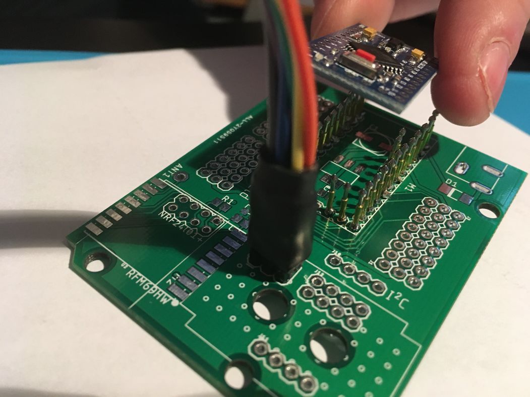
- One can also use PogoPins instead of soldering the Pro Mini (or headers for it) to burn the bootloader or change fuses on the Pro Mini via the ICSP connector.
All design files are available on GitHub: https://www.openhardware.io/view/538/Arduino-Pro-Mini-IO-Shield
-
Finally got the PCBs from AllPCB.com (cost 5 Euros and took a total of 7 days from order submission to free DHL delivery to Europe!!!) for my own MySensors Arduino Pro Mini prototyping board. Unfortunately the soldering iron broke during my assembly, so it's not fully finished and I couldn't test it yet, either...
This board is inspired by the Nano IO shields that are offered on AliExpress and improves it further for my needs (and switched to the Pro Mini instead of the Nano).
- Each analog and digital pin of the Pro Mini has its own VCC and GND pins,
- the board also provides its own voltage regulator, solder pins for by NRF24L01+ and RFM69H are provided (plus the 5V->3.3V XC6206 regulator),
- either a tiny 55-pin breadboard or three I²C connectors can be placed on the board.
- One can also use PogoPins instead of soldering the Pro Mini (or headers for it) to burn the bootloader or change fuses on the Pro Mini via the ICSP connector.
All design files are available on GitHub: https://www.openhardware.io/view/538/Arduino-Pro-Mini-IO-Shield
-
A temperature controlled PWM fan controller for my DPS5005 power supply!
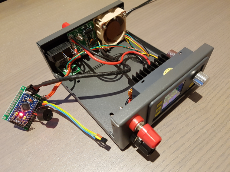
The original 2-wire fan that came with the power supply casing made an incredible amount of noise.
Using PWM to reduce its velocity made it even more noisy :imp:So, I made a fresh start and ordered a quality fan (almost as expensive as the whole casing...)
Using nothing more than a 5V pro mini, piezo speaker, DS18B20 temperature sensor and a resistor I made a full fledged fan controller ;-)
It takes the current temp from the DS18B20 (which will be mounted on the heatsink) and ramps up the fan linearly in the 30..60 C range. Below 30 C, the fan is off.
If RPM readback indicates a stalled fan, or DS18B20 returns wrong values the buzzer will force me to invest what's wrong :muscle:http://yveaux.blogspot.nl
-
A temperature controlled PWM fan controller for my DPS5005 power supply!
The original 2-wire fan that came with the power supply casing made an incredible amount of noise.
Using PWM to reduce its velocity made it even more noisy :imp:So, I made a fresh start and ordered a quality fan (almost as expensive as the whole casing...)
Using nothing more than a 5V pro mini, piezo speaker, DS18B20 temperature sensor and a resistor I made a full fledged fan controller ;-)
It takes the current temp from the DS18B20 (which will be mounted on the heatsink) and ramps up the fan linearly in the 30..60 C range. Below 30 C, the fan is off.
If RPM readback indicates a stalled fan, or DS18B20 returns wrong values the buzzer will force me to invest what's wrong :muscle: