What did you build today (Pictures) ?

-
So I have all of the keys soldered in and wired. I did some simple tests to see how things were working. I tested with a font size of 2, and again with a font size of 4.
Font size 2.
https://youtu.be/7tu7ZgkpF-0Font size 4
https://youtu.be/acMMex0eIVs -
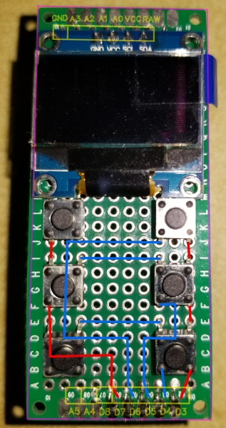
So last night I got the display connected and I now have the Adafruit sample code running on it:
https://youtu.be/knaLySC4X6ITonight I will be installing the buttons and hopefully working on some test code for the buttons and the screen. Here is my proposal for the switch wiring. The red traces are for the columns, and the blue are for the rows.
One thing that I would like to do with this is to possibly display some animated graphics for the current weather condition. Seeing the falling stars at the end of the Adafruit test code made me think of rain or snow falling. Something like that might go outside the limits of the pro minis memory, but hey, never hurts to try.
@dbemowsk said in What did you build today (Pictures) ?:
Seeing the falling stars at the end of the Adafruit test code made me think of rain or snow falling. Something like that might go outside the limits of the pro minis memory, but hey, never hurts to try.
Hey Nice Work!
I see you are using I2C, vs SPI... that may be why your display is so much slower than the demo in the Adafruit video.
Can't wait to see the final board!
-
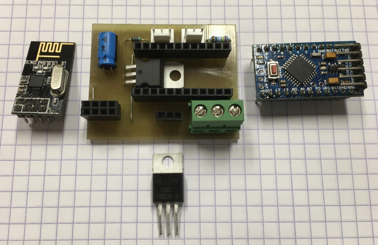
Today I build a basic node for temperature (DS18B20) and analog input. Most of my nodes feature a DS18B20 connection as it only 'costs' a 4k7 resistor and a connector.
PCB is etched.
@boozz What are those 3 pin male connectors called?
-
@neverdie said in What did you build today (Pictures) ?:
@boozz What are those 3 pin male connectors called?
I guess that is molex 3 pin tht pcb connector, like this https://uk.rs-online.com/web/p/pcb-headers/4838477/
-
Hi
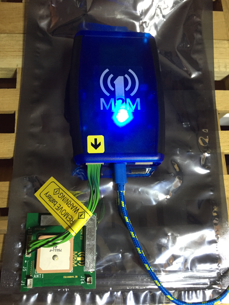
Its been a long time since I made something Mysensors.But now I made my first WIFI node with led dimmer. Using the ESP8266 NodeMCU.
I use the VeraPlus and made a new Mysensors Device, and put in the IP of the NodeMCU.
This is not my last wifi node. I am thinking of making a motion/temp sensor next :-)

and the box.

-
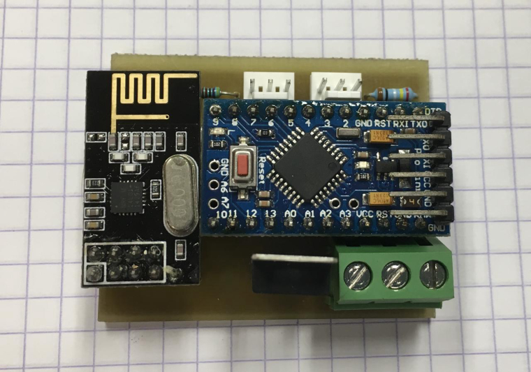
one step further...
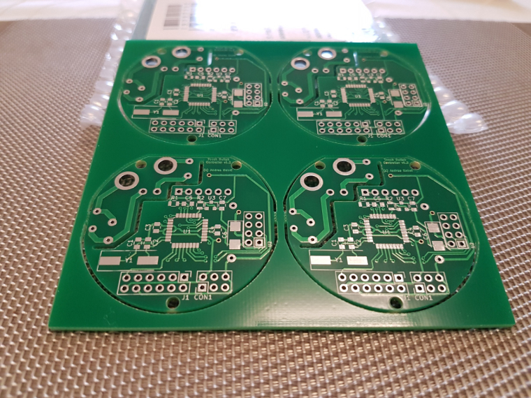
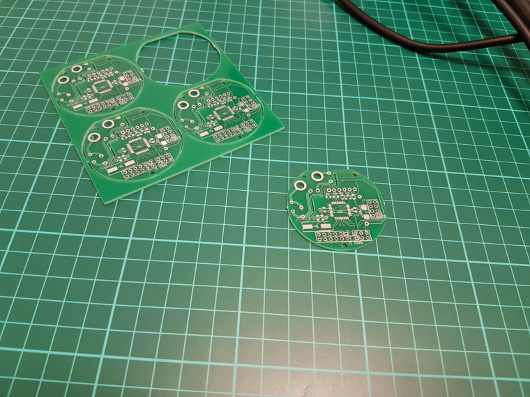
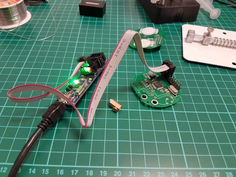
ISP works, FTDI works, test code works, and looks like a genuine board :)
now comes the hard part :D -
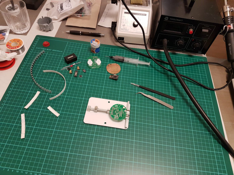
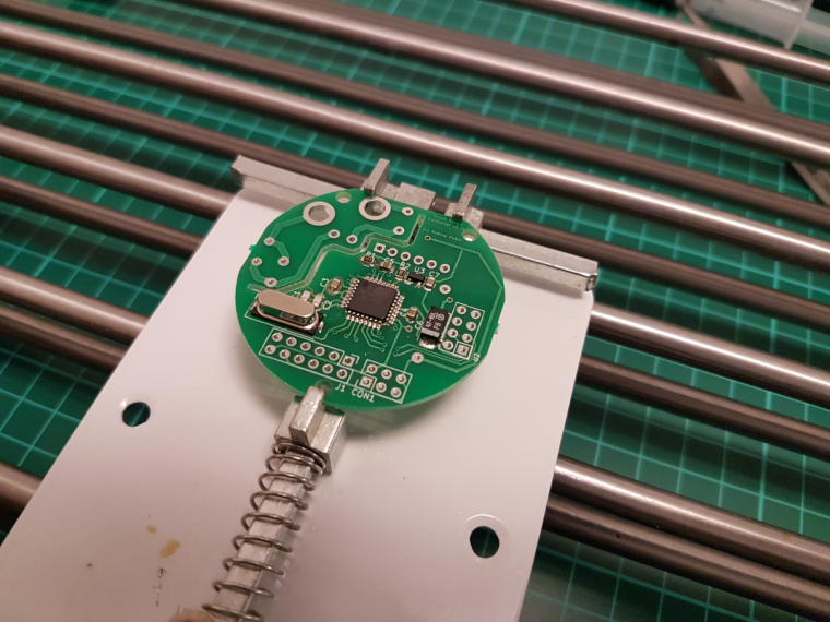
@andrew
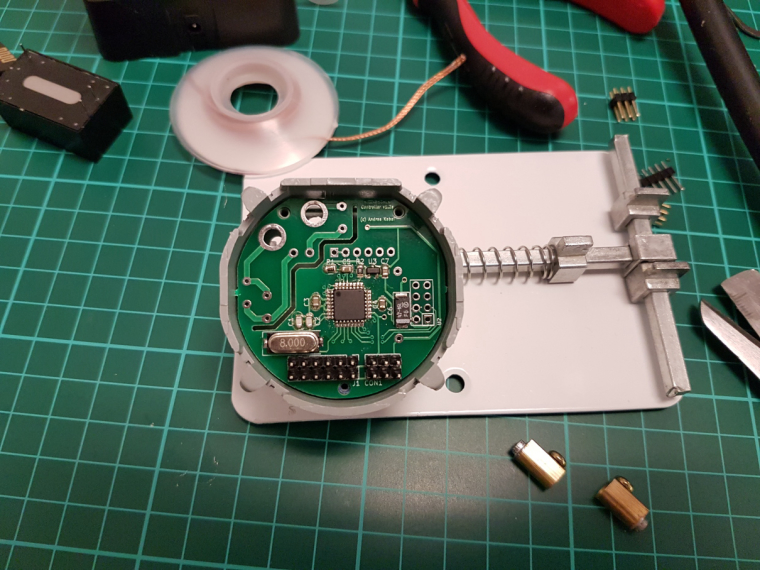
What is that spring loaded contraption? Is it for holding your PCB while you solder it? If so, I can see how that would be handy.@neverdie said in What did you build today (Pictures) ?:
What is that spring loaded contraption? Is it for holding your PCB while you solder it? If so, I can see how that would be handy.
yes. I have a "third hand" station as well, which is good for through hole parts and pcb handling, but for smd, this could be a life saver.
this is the exact item which I ordered and which you can see on the photo:
https://www.aliexpress.com/item/8-12cm-Fixture-Motherboard-PCB-Holder-For-Mobile-Phone-Board-Repair-Tool/32767458535.html -
Today's progress on the new switch consists of finishing the basic 3D model of the wall switch plate and working on some of the programming.
For the wall plate design I do not have buttons as of yet, but the main part of the wall plate turned out good. I did the initial print in yellow because I am out of white at the moment. I am still trying to figure out the best way of printing it. In the video, you will see that the tabs are looking a bit rough. That is because I printed this one face down with supports for the tabs. If I decide to print them that way, it won't be bad because the tabs will be hidden under the wall plate cover. I will try printing them both ways to see which comes out better.
For the programming, I created a couple bitmap icons and did a sample of those icons animated on the screen. The animations toggle back and forth and each runs for about 10 seconds. One bitmap is a rain drop, and the other is a snow flake. The idea is to use these to display weather conditions. I will probably design some clouds and a sun as well and have 4 possible animated weather displays.
https://youtu.be/icre7xeprJI -
one step further...
ISP works, FTDI works, test code works, and looks like a genuine board :)
now comes the hard part :D@andrew
Where did you buy that green thing that sits on your work desk (it has some kind of ruler on it and squares). I don't know how it's called but I keep seeing it and I think I want one too. Thanks. -
@mtiutiu
here I use esd safe mate etc when I do electronics (maybe too much paranoid.. and I don't know if there are with ruler), but these green mates are nice for tinkering, sure.
if you google "cutting mate ruler" you'll find what you want -
@andrew
Where did you buy that green thing that sits on your work desk (it has some kind of ruler on it and squares). I don't know how it's called but I keep seeing it and I think I want one too. Thanks. -
@andrew
Where did you buy that green thing that sits on your work desk (it has some kind of ruler on it and squares). I don't know how it's called but I keep seeing it and I think I want one too. Thanks. -
@mtiutiu I got one of those blue silicon heat resistant mats with magnets so I can use the heat gun over it
@gohan said in What did you build today (Pictures) ?:
@mtiutiu I got one of those blue silicon heat resistant mats with magnets so I can use the heat gun over it
Do you have a link for that? Sounds very useful, especially when soldering things that might get very hot (though maybe I won't need it as much after I get the PCB holder).
-
from my previous posts the PCB CNC milling came out as an interesting topic. maybe another method, working with photo resist PCBs and UV exposure, could be interesting for others. so, for those, who are interested in this, I just documented my solution (not the technique, but my tool) recently.
-
@gohan said in What did you build today (Pictures) ?:
@mtiutiu I got one of those blue silicon heat resistant mats with magnets so I can use the heat gun over it
Do you have a link for that? Sounds very useful, especially when soldering things that might get very hot (though maybe I won't need it as much after I get the PCB holder).
@neverdie they get on sale quite often on banggood but are also available on aliexpress: usually they are on 3 sizes and the biggest has some slots with a lid and others with magnets; there are also some small slots with numbers to keep track of the screws you are disassembling and a ruler at the bottom
-
from my previous posts the PCB CNC milling came out as an interesting topic. maybe another method, working with photo resist PCBs and UV exposure, could be interesting for others. so, for those, who are interested in this, I just documented my solution (not the technique, but my tool) recently.