What did you build today (Pictures) ?

-
Tonight I changed the mechanic trigger to a optocoupler on my doorbell node. I went with some sort of half good solution.
8v AC (Doorbell activated) -> Diode (Not a full bridge, just a support capacitor) -> Voltage divider -> optocoupler > D3. Worked out great, but might be one of the ugliest nodes I have :)Testing/Soldering/Deployment:
-
I changed the form of my integrated nRF52832-protoboard:
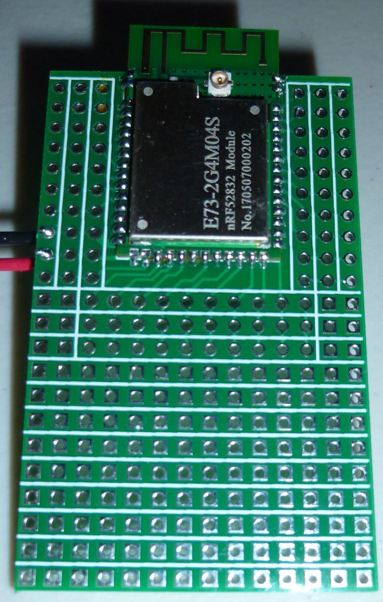
Previously, I was using: https://www.openhardware.io/view/472/Ebyte-nRF52832-Prototyping-Board
-
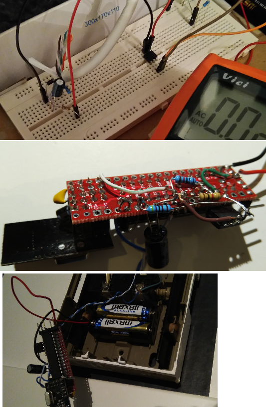
Today I made some small changes to a battery node. Once again I had copy/pasted all battery code but forgot the internalReference in setup() (since I copy from another node sketch). So I now created a dedicated file for battery code I can use to copy from... and once again I remembered I'm not a coder... But it works.
https://github.com/sundberg84/MySensors2.0.0/blob/master/BatteryMeasurer/BatteryMeasurer.ino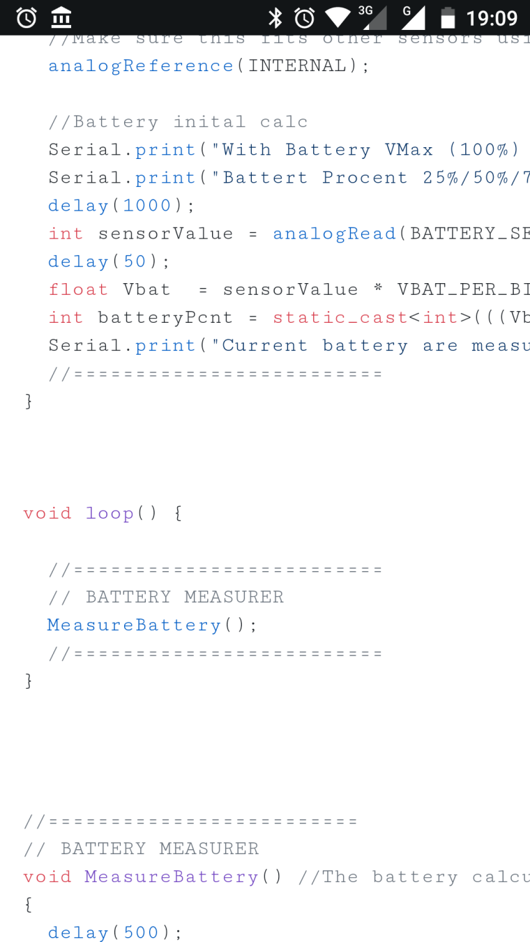
Controller: Proxmox VM - Home Assistant
MySensors GW: Arduino Uno - W5100 Ethernet, Gw Shield Nrf24l01+ 2,4Ghz
MySensors GW: Arduino Uno - Gw Shield RFM69, 433mhz
RFLink GW - Arduino Mega + RFLink Shield, 433mhz -
Today I made some small changes to a battery node. Once again I had copy/pasted all battery code but forgot the internalReference in setup() (since I copy from another node sketch). So I now created a dedicated file for battery code I can use to copy from... and once again I remembered I'm not a coder... But it works.
https://github.com/sundberg84/MySensors2.0.0/blob/master/BatteryMeasurer/BatteryMeasurer.ino@sundberg84 Not to be critical or get off topic, but it's percent, not procent
-
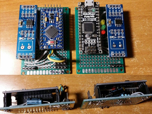
Simple RS485 gateway and node for two BME280 sensors:
-
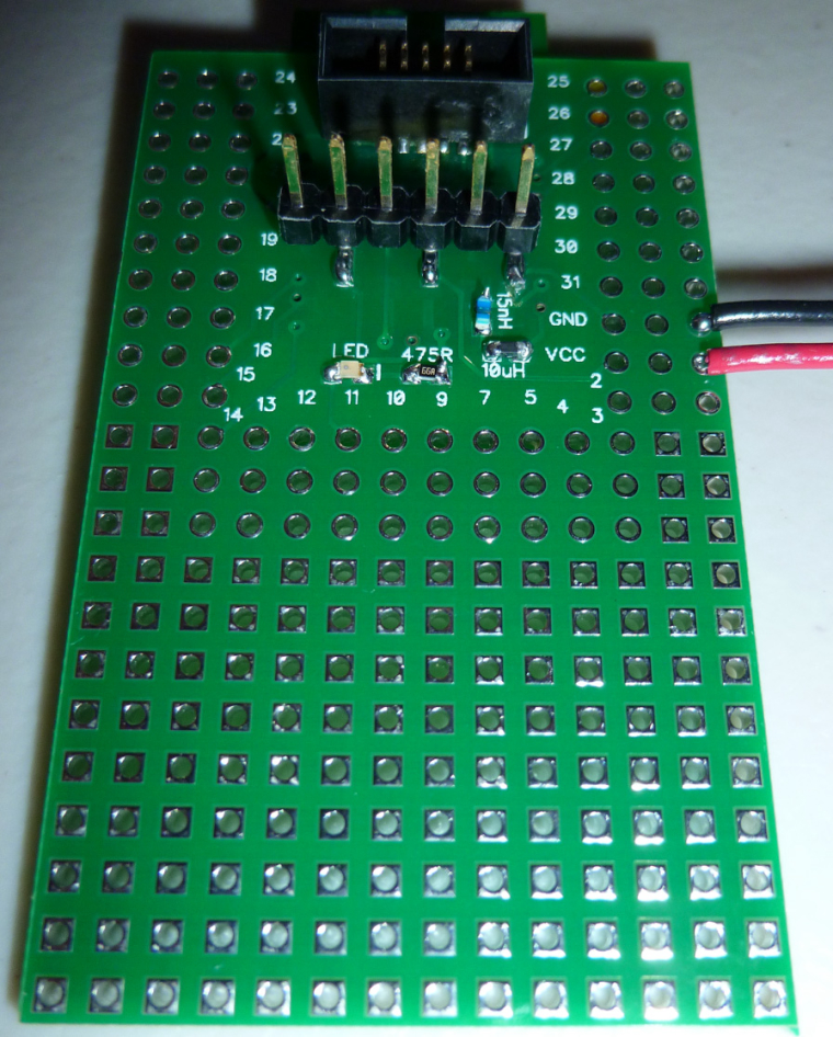
Made a small tool to simplify the extraction of serial debug data from a 10-pin IDC connector and reading it from a typical 6-pin FTDI module.
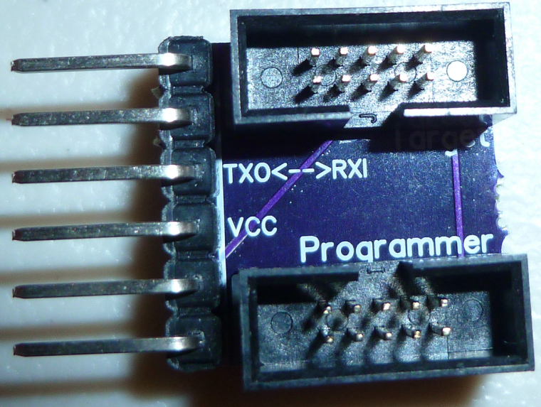
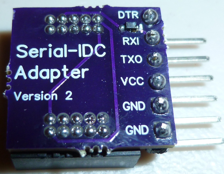
The 10-pin IDC connector is what's most commonly used for programming nRF5x modules. -
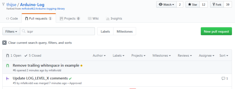
Not really MySensors-related, but I found a nice logging library for Arduino that I'm using in a project. The library was orphaned some time ago, but now has a new maintainer. I assisted with an update of the documentation and some source code cleanup.
-
I made an nRF52832 board today with 5 different colored LED's on it: red, green, yellow, orange, and blue. Mostly I think it may be useful while debugging code. All the LED's except for blue emit light all the way down to 1.8v source voltage, so it's good for battery powered operation also. The blue lights up all the way down to 2.4v, and I had to grapple with a 0403 LED to get that low of a voltage for a blue LED. In the end it was so tiny that I couldn't see the polarity of it, so I hit on the idea of running a blink program and seeing whether it would light up just before I soldered it in place. That worked. :)
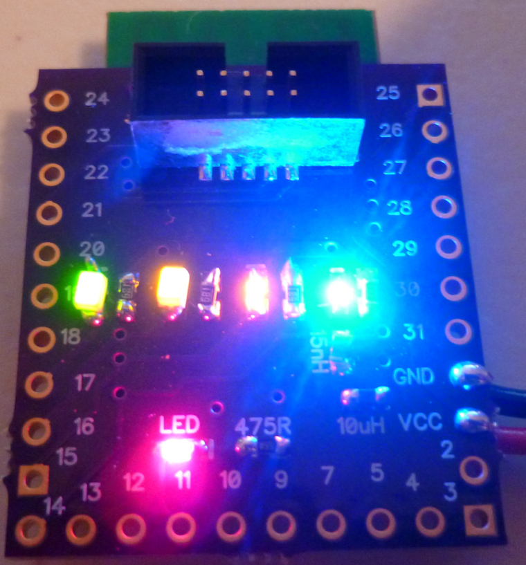
Also, this board channels its serial output over the 10-pin IDC connector, so I used the tool I posted yesterday to read it. Works great, and now I don't have a six pin FTDI connector cluttering up the PCB. :)
-
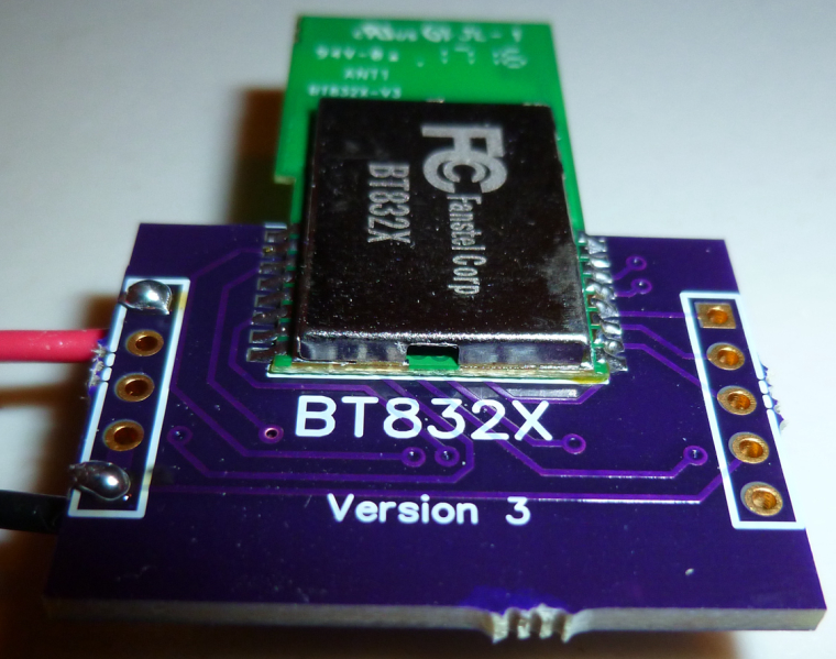
Today my boards for the BT832X (that's an nRF52832 with both PA and LNA) arrived from OSH PARK, so I put one together to try it out:
-
A (long) time ago I had my own Android app which talked xmlrpc to a Python script, which talked serial with my Arduino which in his turn talked 433 Mhz to our outlets turning lights on and off. All was dandy until Android 4 came along and something stopped working security wise and we were send back into the middle ages.
Today I successfully got MySensors working enabling me to read temp/hum from a node and letting me send Elro signals into the air over 433Mhz from OpenHAB2. Now I can scale, extend and upgrade my sensors and actuators I can move forward and start improving our home.

-
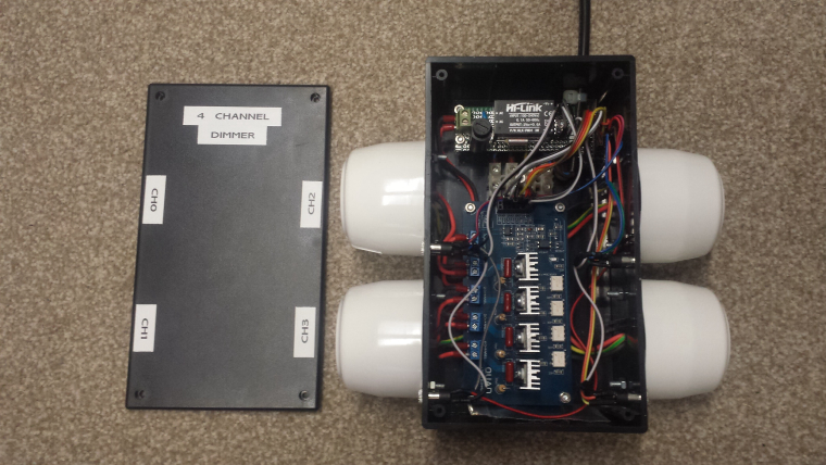
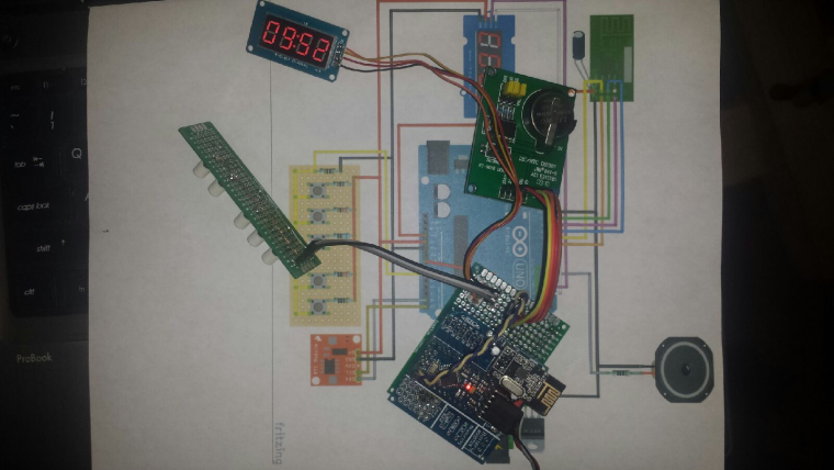
Today I completed the installation of the first of my 4 channel 240V LED light dimmers. This is installed in the roof and supports 4 buttons to turn on/off/increase/decrease each channel. It uses an AC zero crossing detector circuit and can be configured for leading or trailing edge dimming.
-
Last night I made a enclosure to my new outdoor weather station/node. It is made from 2x 70mm sewer pipe end caps and a small sewer pipe to keep them together. Works surprisingly great and looks good.
Now its painted black and drying - lets hope I can find any daylight this week and mount/deploy it.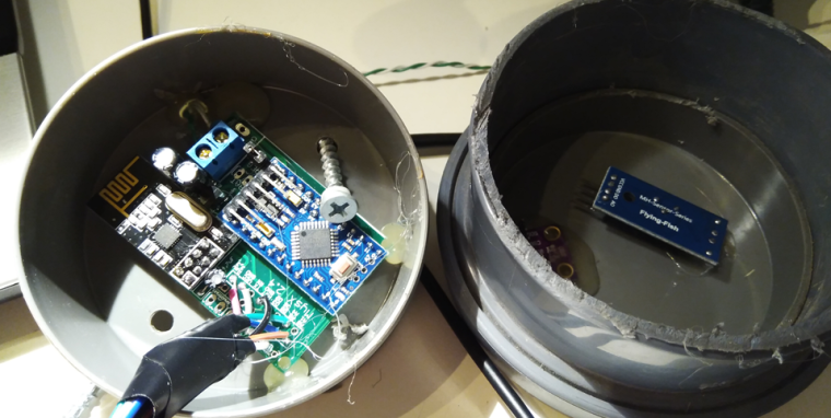
Controller: Proxmox VM - Home Assistant
MySensors GW: Arduino Uno - W5100 Ethernet, Gw Shield Nrf24l01+ 2,4Ghz
MySensors GW: Arduino Uno - Gw Shield RFM69, 433mhz
RFLink GW - Arduino Mega + RFLink Shield, 433mhz -
Last night I made a enclosure to my new outdoor weather station/node. It is made from 2x 70mm sewer pipe end caps and a small sewer pipe to keep them together. Works surprisingly great and looks good.
Now its painted black and drying - lets hope I can find any daylight this week and mount/deploy it.
@sundberg84 If this is going to be out in the sun, I would think you'd want it white. Black is going to heat up your electronics quite a bit.
Vera Plus running UI7 with MySensors, Sonoffs and 1-Wire devices
Visit my website for more Bits, Bytes and Ramblings from me: http://dan.bemowski.info/ -
@sundberg84 If this is going to be out in the sun, I would think you'd want it white. Black is going to heat up your electronics quite a bit.
@dbemowsk - No worries, no sun! All below a roof so I get shade all the day. The roof is black so I need it to blend in as well.
-
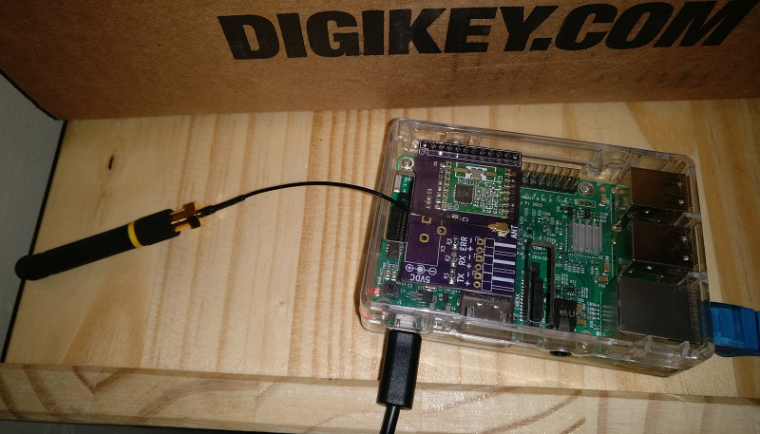
I soldered together the PCB I made for my RFM69 Pi Gateway. Next step is to put it in a nice enclosure
-
I soldered together the PCB I made for my RFM69 Pi Gateway. Next step is to put it in a nice enclosure
A set of Node-Red nodes to decode OpenTherm messages produced by thermostats and Central Heating systems: https://github.com/Yveaux/node-red-contrib-opentherm
It can e.g. replace the OpenTherm Monitor software from otgw by InfluxDB/Grafana :+1: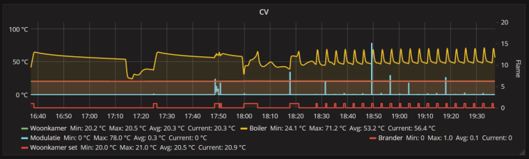
Not a MySensors project, but nice anyway ;-)
-
I did a quick port of my earlier project to make a breakout board for the BC832:
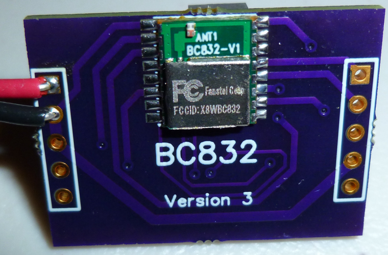
What's interesting about the BC832 is that it is a complete nRF52832 system: 32-bit ARM Cortex 4, wireless, flash, memory, RTC, and antenna, and the whole thing is smaller than a dime:

Of course, my ported breakout board, being as large as it is, doesn't do it justice. That's OK, though, because its main purpose is just to take the BC832 for a test drive. -
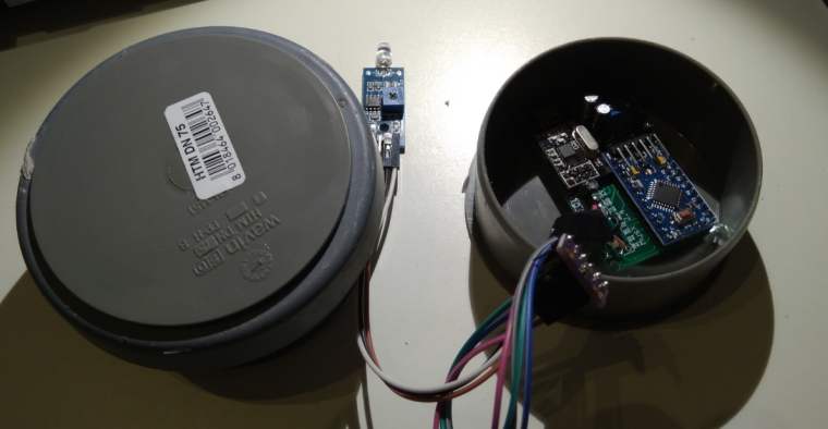
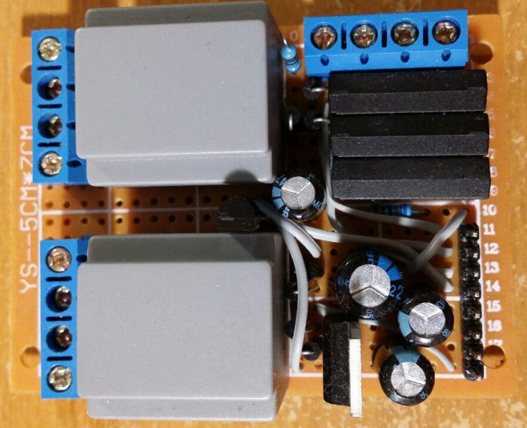
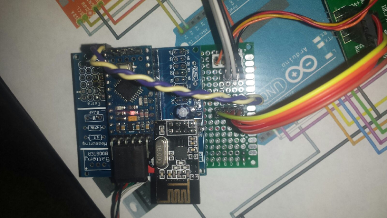
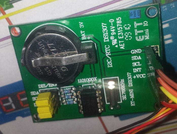
Power (lower half) and external interfaces (upper half) PCB for my "entrance" MySensors node (unregulated voltage, +5V, +3.3V, doorbell detector, electronic door lock status, temperature, etc). I'm using conventional 220V=>6V transformers as main power supply and as simple 220V presence detector for doorbell.
-
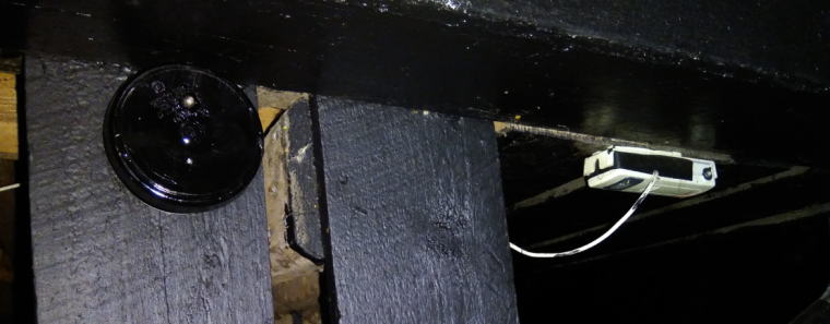
Let me present - How NOT to deploy a MySensors Node! Here is how you do: 1) Skrew everything solid to a wall 2) Power it up and make sure you have shorted a SDA / GND or VCC on your BMP sensor just because you dont doublecheck the colors 3)Forget to enable # My debug 4)Fetch your last BMP sensor but drop it on the lawn (pitch dark outside) 5) Spend 30min with a flashligh in 5dgr C searching for the sensor and try it out once you find it. 6) Nothing works so Un-screw everything and connect it to FTDI inside at your computer, reupload the sketch with debug. - Now everything works fine (with the first sensor) for some unknown reason. 7) Skrew everything back again! 8) Find out the BMP sensor is not working 9) Debug Serial (atleast I got to use my new logger) 10) Find out a short on the MysX connector due to bent wire.
New and old sensor - side by side.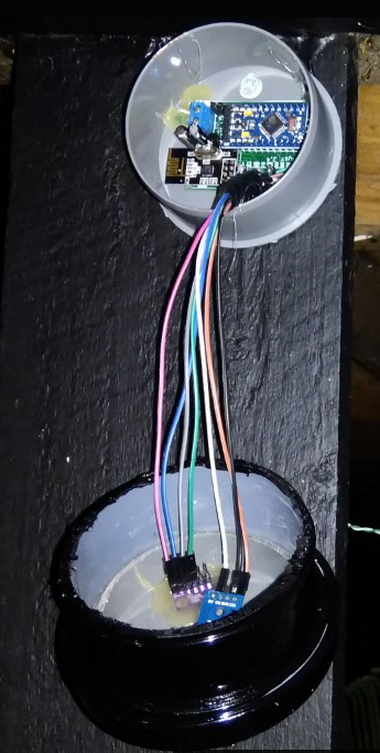
Controller: Proxmox VM - Home Assistant
MySensors GW: Arduino Uno - W5100 Ethernet, Gw Shield Nrf24l01+ 2,4Ghz
MySensors GW: Arduino Uno - Gw Shield RFM69, 433mhz
RFLink GW - Arduino Mega + RFLink Shield, 433mhz