What did you build today (Pictures) ?


  • Mod

    @mcqueen I have not tried, and I have no plans to try. Sorry.


  • @mfalkvidd no problem, thanks


  • So today I created a simple python script to bridge serial gateway with mqtt bus on my RPI:
    https://github.com/mczerski/MySensorsSerial2MQTT

    This is because I already use spi for nrf24 module mounted on a custom pcb so there is no room for another spi device.


  • Hardware Contributor

    0_1517069081859_IMG_20180127_170256.jpg

    I'm building a wine rack for my wife in a celler room (currently 14 dgr with 4 dgr outside). I mowed my beer cooler temp node (rfm radio) to measure how much the temp changed over the day. I wrote a script in Lua/Domoticz that each time it changes 1dgr it should notify me. Apparently is a stable temp the most important to store wine.

    All ideas how I can automate the shit out of this wine-room are appreciated.

    • LCD display with temp/hum (both on the floor and celling) (Red needs apparently cooler than white wine... Or the opposite).

    • I'm thinking about to try a passive cooler. A burried hose/pipe in a loop with a 12v fan/pump and temp. My idea is that if I rotate the 14dgr air in a say 20m pipe under ground it should cool the air some . This needs to be automated to keep the temp stable.

    • light. Some sort of led strips.


  • @sundberg84 Yeah, this brings back memories, particularly of quite a few hangovers.
    I used 3 and four wide fireclay pipes for bottle storage, they were used for ducts back in the day before plastics took over, cable went optic fibre. I noticed recently here they are back in stock in stores as....yep...wine storage racks.... but wacko pricing relatively...
    The beauty of the fireclay was it's slow temperature and humidity change, and this formed the bulk of the thermal mass in the cellar I made below the floor.
    I used a 150mm glazed ceramic drainage pipe dug in under the garden as a loop (rope caulked joints - anybody remember them), from memory down about 1.5m, both avoiding frosts and baking sun, don't think the temperature varied over a degree all year round, the ground acting as a massive heatsink which maintained a constant temperature all year round.
    Only when the hatch was opened did the temperature jump, a small fan kicked in when the hatch was closed and ran for 30 minutes, a second contact switched on the lights and shut them off, long before LEDs were so prevalent, old reliable (until you were depending on them) incandescent bulbs.
    That was it really.
    Biggest problem I found was humidity in the early days, probably the fresh construction...


  • Hero Member

    My wine rack is at the store. πŸ˜‰


  • Admin

    @sundberg84

    Why not just collect the temperatures over time, in f.ex. influxdb, and then use grafana to analyze data? (Instead of pushing messages to your phone whenever the temperature changes..)


  • Hardware Contributor

    @tbowmo well I have Domoticz to collect data. Maybe your alternative is much better but I can't change from Domoticz without redo everything. The push is just to get a heads-up how often or changes but I can go into Domoticz and follow 15 min updates as well on a daily, weekly and monthly graph .


  • Mod

    @tbowmo as the temperature doesn't change that quickly, the 5 minutes Domoticz interval it is OK. As soon as you see a daily variance within your requirements, you are good


  • Was I right to assume that the push of temperature changes to the phone every degree was simply for the initial testing to see quickly how often it would change?


  • I finally got a BT832 (NRF52832 from Fanstel) to talk to my NRF24 gateway. I got the NFR5s a while ago. Made a quick breakout board (quick to design, but slow delivery). In the mean time, I configured a STM32 "Blue Pill" as a Blackmagic Probe to program it. I had to get the latest Sandeep Mistry NRF5 files from github in order for it to support the blackmagic probe, but . . . it worked : ) So far I have just run the MockMySensors and it shows up on Domoticz.
    0_1517119518925_20180128_004035.jpg


  • Admin

    @sundberg84
    With a little bit of nodered injected in the stream, you could have domoticz running without ever noticing that influx etc is getting the data as well πŸ™‚


  • Hardware Contributor

    6.3 days or 152hours just inst good enough - this is what my logger managed to do with 2xAA debugging a temp/hum node sending every 15min. Its below 50% to target (14 days) but this included the leds was on all the time... how much can a 2x leds do 😐 ?? Next experiemtn...

    0_1517140948433_Logger6h.png


  • @sundberg84
    @tbowmo
    Domoticz can also push the data to influx DB. See Settings>More Options>Data Push


  • So for a few days now I have been working on my idea for a homebrew CNC machine made from mostly salvaged parts. This weekend I made some good progress getting the Y axis drive assembly mostly done. I have not tested anything yet, but I hope to in the next few days. Anyways, here is what I have...

    The stepper motor is one salvaged from an old dot matrix printer. The gear on it was press fit on the shaft with no real way to get it off, so I opted to make a geared drive assembly. I realize that this will slow the Y axis down, but it should also give it a bit more precision. Below is the stepper motor.
    0_1517204931227_b940ccdf-0d30-4a67-bfe2-071e6eec469a-image.png

    For mounting it, I designed this adapter plate which carries a steel roller bearing for the screw shaft.
    0_1517205082429_fe119ca7-5e6d-48b2-bc48-ba86a09ed33c-image.png

    This is an early mounting plate design before I added the upper and lower mounting tabs. This shows the gear with the shaft attached. The gear was made using an OpenSCAD gear library.
    0_1517205252644_2d35f97c-b9b9-482c-b811-f7562f164049-image.png

    Yesterday I designed the bracket that attaches to and drives the Y axis platter/build plate (Sorry, forgot to take a decent pic of that part).
    0_1517205734481_60ec4f33-b3c8-4ead-83cd-ca103751669d-image.png

    Today I was able to finish the front and rear frame braces and got parts rough fitted together. the 2 rails with the small white linear bearings are some rods that were salvaged from a couple old scanners. These were used as the rail for the scanner head. I have pics of the full assembly as well as the motor assembly mounted on the rear brace.
    0_1517205974794_758e9eae-82f2-462d-968a-17ea5ca0307e-image.png 0_1517205984333_5e431750-c309-480c-98a4-5475945bd9a6-image.png

    I can't say how well the design will work, if at all, but it has been a fun journey so far trying.


  • @dbemowsk
    Well it looks as if your 3D-printer works fine πŸ˜€

    What I would be slightly worried about is if with the given size of the rods the stiffness of the structure would be enough.
    Hope to see more from this project in the near future.
    Good luck!


  • @boozz I will be curious to see if I can get enough precision to do PCBs. I have yet to buy a GRBL board to control it. For now I am going to use the UNO that I have for testing just to do test runs of the servos until I get one. This is the one I have been looking at:
    https://www.ebay.com/itm/Arduino-CNC-Shield-Kit-UNO-Board-4x-DRV8825-Drivers-Package-Deal-FREE-USA-SHIP/292174947187?hash=item4406fbe373:g:A0sAAOSwJThZpeKr
    I will also have to figure out the gear ratios of the motor assemblies once I am done because I am sure I will need them to calibrate the GRBL setup. I know on this part of it I have about a 4.8:1 ratio from the motor to the large gear, but I'll have to figure out steps per cm or steps per mm or something. If anyone knows a good way of figuring this out I am all ears.

    Thanks for the upvotes.


  • Hero Member

    @dbemowsk It will save you the hassle of upgrading if you buy a control board with GRBL1.1f already built in.


  • Mod

    @dbemowsk said in What did you build today (Pictures) ?:

    If anyone knows a good way of figuring this out I am all ears.

    It would expect making a large movement using a defined number of steps, and measuring the actual distance moved with a caliper will give you a rather accurate steps/mm.
    However, I hope this ratio is constant over the whole range, given the 3d printed gears and expected backlash...


  • @yveaux as far as the backlash, i had already thought of that. I have 2 coupler nuts with a spring in between to handle the little bit of backlash that there is. I only had a thin spring though. I want to find a stronger one.


  • @sundberg84
    Redundancy, maybe you should get a second temp/humidity measurement device, just in case your current beer cooler temp node breaks down...


  • Mod

    @bjacobse or get redundant beer coolers πŸ™‚ Important to always have cool beer.


  • @mfalkvidd
    True but usually wines have a higher price and a more valuable - not starting a discussing/flame war what is best to drink...


  • @mfalkvidd Can't have too much redundancy there...


  • Hero Member

    Made this 12 button keypad. Requires only one analog pin to read which button is pressed, and any button press can also wake an arduino from sleep:
    0_1517277256612_12keypad.jpg
    Consumes no power when no button is pressed.


  • Hero Member

    Here's a thread which covers it in more detail: https://forum.mysensors.org/topic/8936/6-8-buttons-battery-remote-node/36


  • @neverdie what happens when you press two or more buttons ??


  • Hero Member

    @rozpruwacz Well, with the sketch I wrote (see link), you'd get the value of the first button pressed, and that's it. You'd have to release all the buttons before selecting a new button.

    In terms of the hardware itself, there's an order of precedence to the buttons, so at all times you'd only be able to read the value of a single button, even if more than one button were pressed. In a multi-button press scenario, the buttons of lower precedence are ignored.

    It's a good question though. If you needed to read more than one button simultaneously (such as, for example, move an RC car forward and turn right at the same time), this wouldn't do it. Seems like such a circuit would be possible though, maybe even one based on simple voltage dividing like this one. Somehow you'd need to sum unique resistances for each button pushed instead of just choose a single resistance. I can imagine doing that for a few buttons on an arduino, but maybe not as many as 12.


  • @neverdie I'm asking because I Was trying to do something like this. If there was a resistor values set that would make all 2**n (where n is the number of buttons) choices spaced enough in voltage domain it would work, but I couldn't find such a set ...


  • Hero Member

    @rozpruwacz said in What did you build today (Pictures) ?:

    @neverdie I'm asking because I Was trying to do something like this. If there was a resistor values set that would make all 2**n (where n is the number of buttons) choices spaced enough in voltage domain it would work, but I couldn't find such a set ...

    That's why it might work if you needed it for only a few buttons. With only 1024 units of voltage, seems like you'd quickly run out of resolution if you tried to do more.


  • Hardware Contributor

    I built my first MysX daughter board which I will connect to my EasyPCB to drive a led strip.
    This will power everything from 12v so 2 things. Power main board and dim LED strip.

    0_1517346818295_f17d0698-17e1-4842-997e-fa8ddc1d8019-image.png


  • Hardware Contributor

    Do anyone knows it the back of a TO-220 always is connected to GND and if this should be connected to the board GND as well? Currently I have a exposed copper as a heatsink but this copper is not connected to GND.


  • Admin

    @sundberg84

    Depends on the manufacturer / device type.. So look in the datasheet of the one that you want to use.


  • Hardware Contributor

    @tbowmo
    Thank you - I want to be able to use them all/different (ie. 5v, 3.3v, different manufacturer) so I wont connect it and just use it as a heatsink.


  • @tbowmo I agree, it would be per device specs. In many cases I see that connected to the middle pin (whatever that may be), but not always.


  • Hero Member

    Made this two-button nRF52832 remote control:
    0_1517498847917_nrf52_remote.jpg
    It only draws power when one of the buttons is pressed.


  • nice πŸ™‚ what about range of the nRF52832 ? is it better than nfr24l01+ with pcb antenna ? I had problems with nrf24 and now I'm trying with rfm69. From first tests I can tell that it has much better range - but it is slightly larger and requires an antenna ...


  • Hero Member

    @rozpruwacz said in What did you build today (Pictures) ?:

    is it better than nfr24l01+ with pcb antenna ?

    yes


  • Hero Member

    Assembled and tested final version of LoRa Leak Detector:
    0_1517532798060_lora_leak_detector_v15.jpg
    Thanks to an external watchdog (TPL5010), it consumes very little current while sleeping. Also, the external watchdog will reboot the pro mini should it ever become unresponsive, so, in addition, it should be highly reliable.


  • Hardware Contributor

    @neverdie said in What did you build today (Pictures) ?:

    TPL5010

    That's a really nice IC, I was looking for something like that but it seems I didn't search with the right keywords.
    Thank you for sharing the discovery !


  • Hero Member

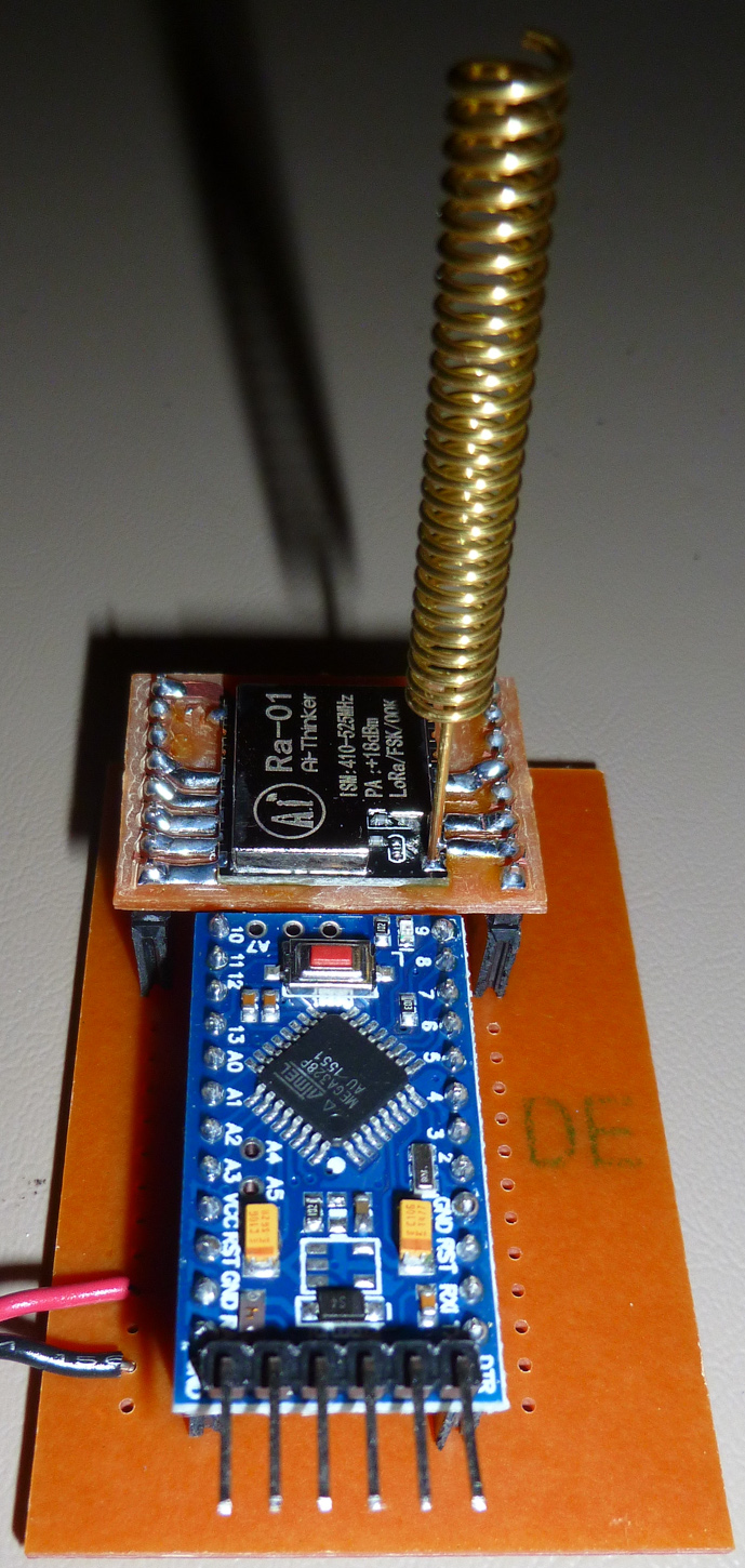
    Made a simple LoRa node using my CNC:
    0_1517982209204_lora_node.jpg


  • Hero Member

    Upgraded it to include two AA batteries and a DS18B20 temp sensor. Future versions will tap the I2C pins on the pro mini, so those will have better TH sensors.

    0_1518188724144_lora_temp.jpg
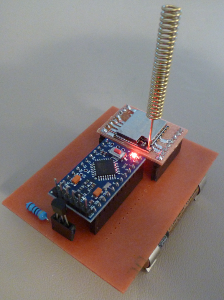
    Range is noticeably better than when I was running the LoRa from just a breadboard. πŸ™‚

    I'm tempted to use a double sided PCB and give the LoRa a more proper and really big ground plane to see if that boosts range even more (at the same power level).


  • @neverdie You can also consider replicating the 1/4 wave against ground in the opposite direction perhaps? πŸ˜‰


  • Hero Member

    @zboblamont said in What did you build today (Pictures) ?:

    @neverdie You can also consider replicating the 1/4 wave against ground in the opposite direction perhaps? πŸ˜‰

    I don't understand what you mean. Can you explain a bit more what that would be?


  • @neverdie Sure.
    A quarter wave on an ideal Ground Plane mimics a half wave, the GP is sort of like a mirror in radio terms for the 1/4 above it....
    Ergo two identical 1/4 waves, one attached to RF feed the other attached to ground, does the same thing, although in fact slightly better...


  • Hero Member

    @zboblamont So, what you are advocating is a dipole antenna? i.e. something notionally similar to this:
    https://www.openhardware.io/view/277/ESP8266-RFM69HW-gateway-with-dipole-antenna
    At least, that is what it sounds like to me.


  • @neverdie Not advocating a dipole as such, only pointing to an alternative to your suggested ground plane at 90 degrees to the base of the antenna. Electrically, the second half of the dipole IS the ground plane, and vice versa.
    With such physically small boards, it is virtually impossible to achieve the ideal ground plane unless the wavelength is very small, I suggested a duplicate helical tied to GND in the opposite direction to your antenna essentially accomplishes the same thing.


  • Hero Member

    Interestingly, I just now checked, and it appears my LoRa leak detectors have even better range still. Maybe it's because GND completely encircles the PCB along all four edges. This may cause me to rethink the design of the gateway node, which up to now has been much smaller than the leak detectors....


  • Hardware Contributor

    0_1518791218187_15187911952321497205782.jpg

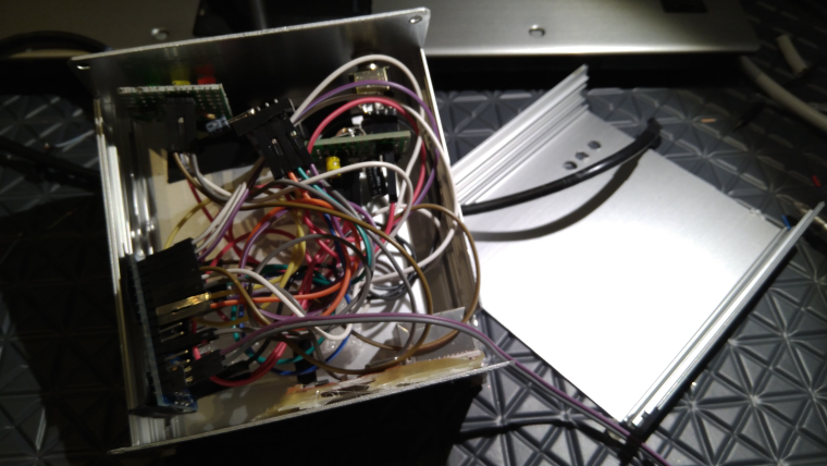
    Today some maintenance on my GW.

    Added a ground wire for debug and also corrected a buildmisstske and grounded the case.

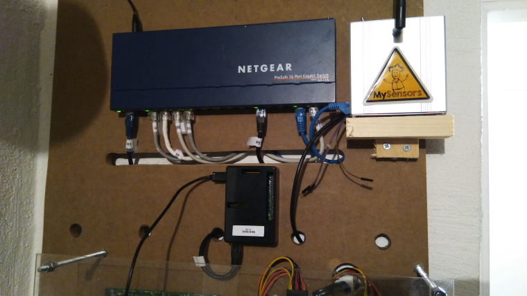
    And relocated (let's hope for the best) it to my new HA DIY board...

    0_1518792236611_15187922282851484593467.jpg


  • Hardware Contributor

    And there was the first failing sensor.... But was it because I changed the location on the gw? Nope... I had a temp/hum right beside the gw which I pushed so it fell on the floor...

    0_1518793080330_Screenshot_20180216-155624.png

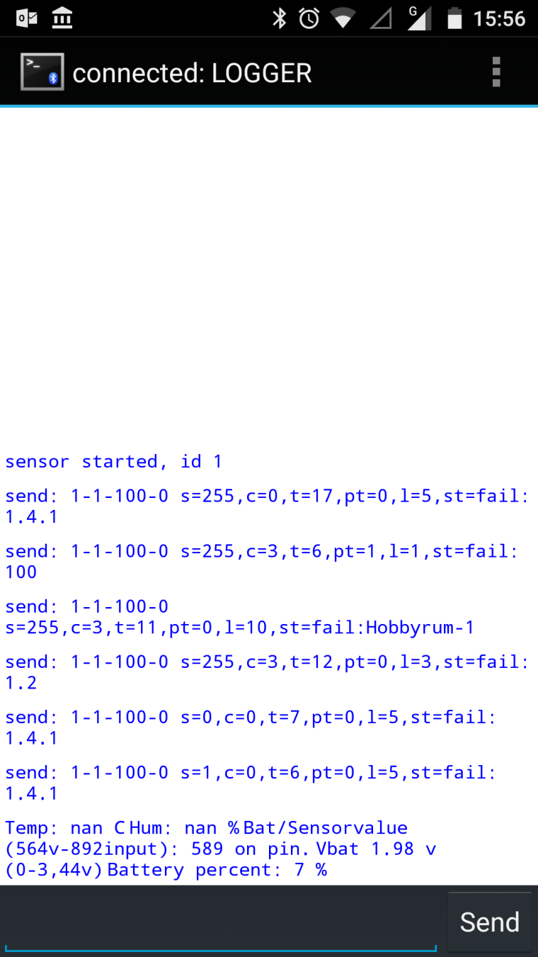
    Radio cap de-attashed and sensor died.

    Easy fix and now back in operation.
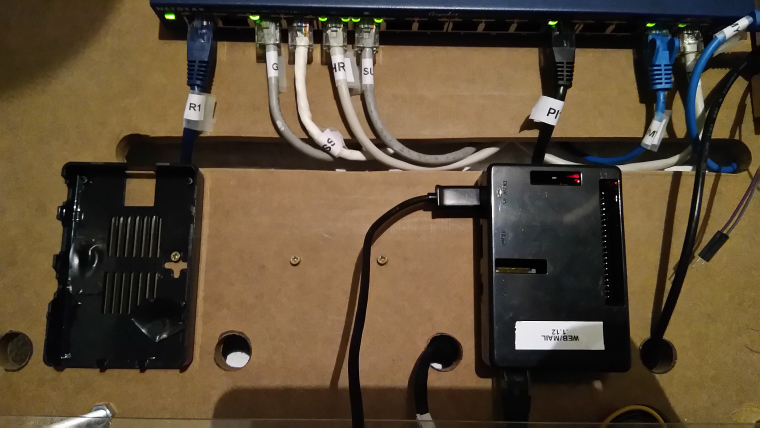

  • Hero Member

    @sundberg84 Sorry for the stupid question, but what holds your WEB/MAIL black box in place?


  • Mod

    @sundberg84 said in What did you build today (Pictures) ?:

    And there was the first failing sensor.... But was it because I changed the location on the gw? Nope... I had a temp/hum right beside the gw which I pushed so it fell on the floor...

    You meant "the first FALLING sensor" πŸ˜…


  • Hardware Contributor

    @neverdie said in What did you build today (Pictures) ?:

    @sundberg84 Sorry for the stupid question, but what holds your WEB/MAIL black box in place?

    Screws.
    0_1518797972773_IMG_20180216_171855.jpg


  • Mod

    @sundberg84 +1 for the mySensors sticker!


  • Admin

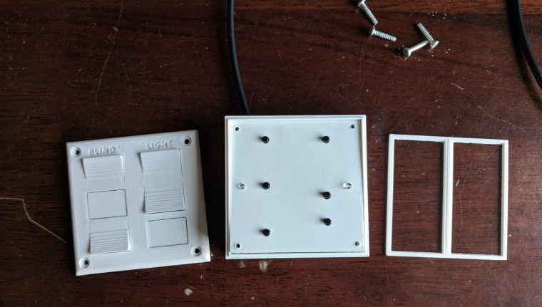
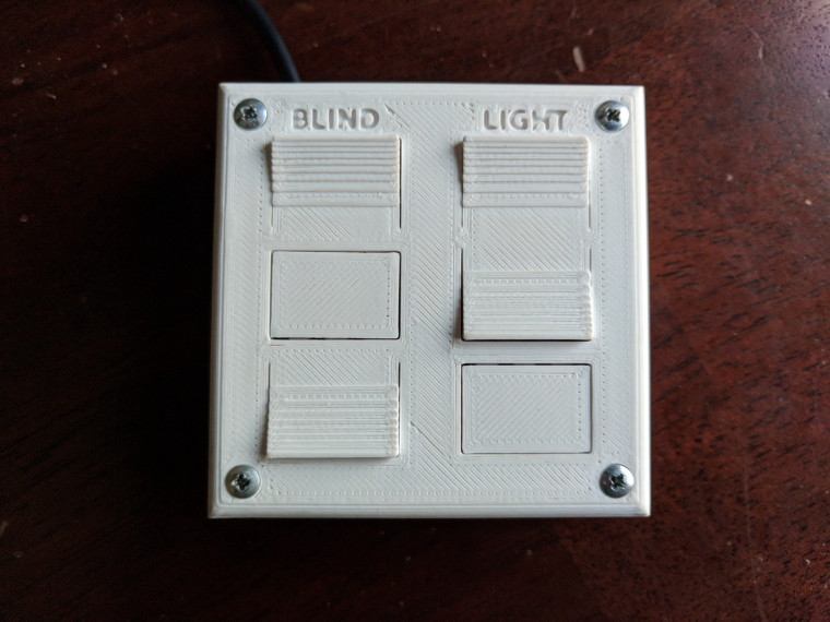
    My son and I finally finished his first MySensors project- a remote control for his room. He wasn't too interested but you have to start somewhere right...? πŸ™‚
    Question for you all... what are you doing (if anything) to vent the fumes from soldering? I haven't really been worried about it in the past but it makes me nervous with my son doing it with me.
    Anyway, here are the pictures.
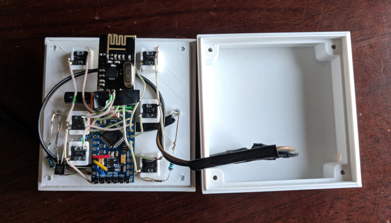
    0_1518837057065_IMG_20180216_171013.jpg
    0_1518837070467_IMG_20180216_171125.jpg
    0_1518837089935_IMG_20180216_171709.jpg


  • Hero Member

    @petewill What up with the red, yellow, and blue wires on the pro mini?

    Also, did you print the case with a volcano?


  • @petewill That's awesome. Did you work with him too on the design of the box? Great job.


  • Mod

    @petewill I put a regular 120mm pc fan to blow the fumes sideways. Not perfect, but I think it is good enough for the short time I spend soldering.


  • Mod

    @petewill is it battery powered? Can you share the code?


  • Hardware Contributor

    @petewill , @gohan I use the same as @mfalkvidd and its pretty much a PC fan with the wires to a 9v battery.... been thinking for a long time to make a more permanent sollution with a tubes from outside....


  • Mod

    0_1518863873465_File-2018-02-17,-11-32-40.jpg
    Today's test was to see if the regular reed switches can be closed by the magnetic field created by a 1A current.

    I got an opportunity to try out my recently USB power meter and adjustable load.

    Since I am not sure how the reed switch is mounted inside the sensor, I tried different orientations but nothing triggered the sensor. I also tried 2A but that wasn't enough either.

    I need a non-invasive way to know if (how much) current is flowing in a DC cable. I was hoping the reed switch would be an easy way. My next hope is something like a SCT-013, unless someone has suggestions for other sensors. Requirements: 6-48V DC. 0.5-10A. I only need to know if the circuit is consuming >0.5A, no need for an exact measurement.


  • Mod

    @mfalkvidd Hall sensor?


  • Mod

    @gohan SCT-013 is a hall-based sensor I think. I was looking for more specific that just the type of sensor.


  • Mod

    @mfalkvidd said in What did you build today (Pictures) ?:

    SCT-013 is a hall-based sensor I think.

    No, it's only a current transformer, and you possibly need (at least) a burden resistor to measure the current. Ofcourse we already have a thread on it πŸ˜‰


  • Mod

    @yveaux yes I've read that thread and I would choose one of the sct-013 variants that already contains a burden resistor.


  • Hero Member

    @mfalkvidd Didn't you play with electromagnets when you were a kid? At least try coiling the wire and maybe putting a metal core inside it. Use a lot of coils. The more the better. Then maybe your reed-type switch would have a chance of seeing enough magnetism to trigger it.


  • Mod

    @neverdie wouldn't that choke the current passing through the coil? He said he needs 6-48V DC. 0.5-10A


  • Admin

    @NeverDie The wires are there in case I need to upload a new bootloader. This sensor one of the first ones I have done where the Arduino isn't easily removable and I wanted to try to make it a little easier in case I had to change it.
    I used an original Prusa I3 MK2 to do the printing. This is in ABS (because I didn't have any white PLA) so the print is a little rougher than if it was done with PLA.

    @dbemowsk Thanks! No, my son didn't help with the case design (yet). It was from a previous project that I slightly modified. My son is 6 so he doesn't really have the attention span to do too much yet. I'm hoping that doing little parts of a project will be fun for him and eventually turn into full projects. πŸ™‚

    @mfalkvidd & @sundberg84 Thanks. I guess I need to rig something up if he is going to be helping me more often...

    @gohan No, it's not battery powered. I didn't want to have to deal with changing batteries and there is a power outlet right near the location he wanted it. Here is the code:

    /**
      The MySensors Arduino library handles the wireless radio link and protocol
      between your home built sensors/actuators and HA controller of choice.
      The sensors forms a self healing radio network with optional repeaters. Each
      repeater and gateway builds a routing tables in EEPROM which keeps track of the
      network topology allowing messages to be routed to nodes.
    
      Created by Henrik Ekblad <henrik.ekblad@mysensors.org>
      Copyright (C) 2013-2015 Sensnology AB
      Full contributor list: https://github.com/mysensors/Arduino/graphs/contributors
    
      Documentation: http://www.mysensors.org
      Support Forum: http://forum.mysensors.org
    
      This program is free software; you can redistribute it and/or
      modify it under the terms of the GNU General Public License
      version 2 as published by the Free Software Foundation.
    
    *******************************
    
      REVISION HISTORY
      Version 1.0 - PeteWill
    
     
    */
    
    #define SKETCH_NAME "Controller"
    #define SKETCH_VERSION "1.0"
    
    //Child (sensor) name that will be sent to gateway
    #define CONTROLLER_CHILD_NAME "Room Control"
    
    // Enable debug prints to serial monitor
    #define MY_DEBUG //MySensors debug messages
    #define LOCAL_DEBUG //Code specific debug messages
    
    // Enable and select radio type attached
    #define MY_RADIO_NRF24
    //#define MY_RADIO_RFM69
    
    #define MY_RF24_PA_LEVEL RF24_PA_HIGH //Options: RF24_PA_MIN, RF24_PA_LOW, RF24_PA_HIGH, RF24_PA_MAX
    #define MY_RF24_CHANNEL  76
    #define MY_NODE_ID 1  //Manually set the node ID here. Comment out to auto assign
    
    #include <MySensors.h>
    #include <Bounce2.h>
    
    #define SCENE_CHILD_ID 0
    
    #define BAUD_RATE 57600
    
    #ifdef LOCAL_DEBUG
    #define dbg(...)   Serial.print(__VA_ARGS__)
    #define dbgln(...) Serial.println(__VA_ARGS__)
    #else
    #define dbg(x)
    #define dbgln(x)
    #endif
    
    //Button Pins -- Arduino Digital I/O pin button is connected to
    #define BLIND_UP_PIN 5
    #define BLIND_STOP_PIN 4
    #define BLIND_DOWN_PIN 3
    #define LIGHT_ON_PIN 8
    #define LIGHT_OFF_PIN 7
    #define EXTRA_BUTTON_PIN 6
    #define LED_PIN A0 //Pin for the LED transistor
    
    #define FLASH_TIME 300 //Amount of time to flash the LED (in milliseconds)
    
    #define ARRAY_SIZE(x) (sizeof(x)/sizeof(x[0]))
    
    uint8_t ledOn = 0;
    uint32_t ledMillis; //Used for tracking the LED flash time
    
    
    //The sceneNum array corresponds with the buttonPins array so if a button pin is read, it will send the scene number to the gateway
    int sceneNum[] = {0, 1, 2, 3, 4, 5};
    
    uint8_t buttonPins[] = {
      BLIND_UP_PIN,
      BLIND_STOP_PIN,
      BLIND_DOWN_PIN,
      LIGHT_ON_PIN,
      LIGHT_OFF_PIN,
      EXTRA_BUTTON_PIN
    };
    
    //Debouncer is used for the buttons.  Need to have the same number as the total buttons.
    Bounce debouncer[] = {
      Bounce(),
      Bounce(),
      Bounce(),
      Bounce(),
      Bounce(),
      Bounce()
    };
    
    //used to keep track of previous values contact sensor values
    uint8_t buttonPrev[] = {1, 1, 1, 1, 1, 1};
    
    MyMessage scene(SCENE_CHILD_ID, V_SCENE_ON);
    
    void before()
    {
    #ifdef LOCAL_DEBUG
      Serial.begin(BAUD_RATE);
    #endif
    }
    
    void presentation()
    {
      // Send the sketch version information to the gateway
      sendSketchInfo(SKETCH_NAME, SKETCH_VERSION);
    
      // Register all sensors to gw (they will be created as child devices)
      present(SCENE_CHILD_ID, S_SCENE_CONTROLLER, CONTROLLER_CHILD_NAME);
    }
    
    void setup() {
      //Set up Pins
      for (int i = 0; i < ARRAY_SIZE(buttonPins); i++) {
    
        // Setup the pins
        pinMode(buttonPins[i], INPUT_PULLUP);
    
        // After setting up the button, setup debouncer
        debouncer[i].attach(buttonPins[i]);
        debouncer[i].interval(100);
        dbg(F("Set up contact Pin: "));
        dbgln(buttonPins[i]);
      }
    
      pinMode(LED_PIN, OUTPUT);
    }
    
    void loop() {
      uint32_t currentMillis = millis();
      for (int i = 0; i < ARRAY_SIZE(buttonPins); i++) {
        debouncer[i].update();
        // Get the update value
        uint8_t value = debouncer[i].read();
        if (value != buttonPrev[i]) {
          dbg(F("Value is for sensor #"));
          dbg(buttonPins[i]);
          dbg(F(" is "));
          dbgln(value);
    
          if (value == 0)
          {
            //Button is pressed send scene value
            send(scene.set(sceneNum[i]));
    
            ledOn = 1;
            ledMillis = currentMillis;
          }
          buttonPrev[i] = value;
        }
      }
      if (ledOn)
      {
        digitalWrite(LED_PIN, HIGH);
    
        if (currentMillis - ledMillis > FLASH_TIME)
        {
          ledOn = 0;
          digitalWrite(LED_PIN, LOW);
        }
      }
    }


  • Mod

    @neverdie said in What did you build today (Pictures) ?:

    @mfalkvidd Didn't you play with electromagnets when you were a kid? At least try coiling the wire and maybe putting a metal core inside it. Use a lot of coils. The more the better. Then maybe your reed-type switch would have a chance of seeing enough magnetism to trigger it.

    Yes, but that would unfortunately completely defeat my purpose. The device should be easy to install (I can't expect the end-user to coil their cable) and work with cables that are designed for >10A which means they will be too thick to coil. I understand that I did not mention all aspects of the use case in my post though so thanks anyway.


  • Hardware Contributor

    @petewill said in What did you build today (Pictures) ?:

    Question for you all... what are you doing (if anything) to vent the fumes from soldering? I haven't really been worried about it in the past but it makes me nervous with my son doing it with me.

    I have a Hakko 493 clone, it has a carbon filter to absorb the smoke (or most of it) so it doesn't smell too much in the room when I need to solder for a long time and I can't open the windows. I don't have a link because I bought it in my local shop (it was cheaper than AliExpress + shipping), but you can easily find similar models or clones of the FA400 by searching "smoke absorber" on AliExpress.

    alt text


  • Hero Member

    @mfalkvidd
    I had a similar requirement recently, which was determining when my CNC was finished. I decided to measure the current to decide that. It's 24VDC and might have a current as high as 6amp in a theoretical worst case, but as little as 0.5a when moving just one of the stepper motors. So, what I came up with was this, which I've tested and it works:
    0_1518882212781_cnc_current.jpg
    Basically, it uses six 5-watt 3 ohm resistors in parallel to create a 1/2-ohm sense resistor, which an arduino then measures the voltage drop across by just doing an analog read from an analog GPIO pin across a voltage divider. I don't really know your use-case, but maybe you could adapt it for your application? You can ignore the LoRa module, which in my case I use to send out a signal to a remote receiver inside my house that the CNC print job (in the garage) is done.


  • Hardware Contributor

    I made a MysX template for anyone who wants to create a MysX board to any EasyPCB in KiCadd.
    Found here: https://github.com/sundberg84/HomeAutomation/tree/master/MysX template EasyPCB

    0_1518893898944_pcb.JPG


  • Admin

    @nca78 thanks! I'll check that out.


  • Hero Member

    Today I made and assembled a board which instantiates the schematic I posted above two days ago on this thread:
    0_1519063093860_endOfCncJob.jpg
    Basically, it sends a wireless signal as soon as the CNC machine finishes its work.


  • Admin

    My old Yamaha YSP-1100 soundbar just decided to die.

    0_1519064477579_20180219_191957.jpg

    After some searching I found the problematic capacitor. A 22uF 600V had dropped to 6uF....

    1_1519064477580_20180219_191926.jpg !


  • Hero Member

    @hek How did you find the faulty capacitor?


  • Admin

    @NeverDie, well, I started my trouble shooting with a lucky google search. For old devices like this, you are often not the first person experiencing a problem.


  • Admin

    I had a good laugh when examining the other board. Is this a normal solution for remote-in?

    0_1519074044722_20180219_215656.jpg


  • Mod

    @hek said in What did you build today (Pictures) ?:

    solution for remote-in

    DIY optocoupler?


  • @hek If this is for a sound bar, I know on some older stereos they had a remote signal out that you could tie into other components in the system. Maybe it's something like that.


  • Mod

    @neverdie could you achieve something similar with a sonoff pow measuring the whole cnc power consumption?


  • Hero Member

    @gohan I don't know, as I'm not familiar with Sonoff, or how sensitive it is.


  • Mod

    It's a WiFi power meter with a relay to turn off the load, so you could set a rule on controller that if measured power goes below a certain amount it will notify something


  • Hero Member

    It's a very good suggestion. If I wasn't already done, I'd try it. If it works, the Sonoff would be simpler and less effort.


  • Hardware Contributor

    Another hour on my... whatever it is.

    0_1519319063465_1519319045376771585256.jpg

    Anyone that can recommend a open source router (hardware) or cheap hardware for pfsense which isn't that big and draws that watt amount.


  • Mod

    WHat do you need a PC for?


  • Hardware Contributor

    @gohan it's a pc with my intention to run pfsense (open source router) but it is old and draws to much power for my taste.


  • How much power does that pc draw?
    Mine:
    Asrock Q1900B-ITX + pico 12V to atx psu + PCIE Intel Nic 2/4 Gbit ports + SSD can run on 20W or less, but I believe the J1900 Celeron lacks AES for VPN if you care about it.

    HP DL 380 G7 2xL5640 hex core, 144GB Ram, 4xGbit Nics, SSD, 90W at idle (99.9% of time) and pfsense is only one of the VMs I constantly run, besides OH2, Ubiquity controller, Nextcloud. The ability to snapshot a development VM, or fork (clone) it is a killer feature for me.

    Another DL 380 G7 in standby is drawing 15W.

    Phu*ck I have some old shitty switches that draw 30-40W, not to mention security cameras, 300-500Wh during the night for all my crazy home automation&security.


  • Mod


  • Hardware Contributor

    the little netgate looks cute, but wondering if it would be enough powerful (for streaming etc.)

    @sundberg84
    when you already have parts laying around, like ram, hdd etc, you could also use intel J3355 or J4205 cpus, maybe better than J1800. J3355 boards are not expensive. Then add a pcie NICs or a simple usb to gigabit..
    I would choose micro atx board because often cheaper, same for ram (more compatible ref vs itx boards sometimes are restrictive), and it may be more flexible for pcie slot. That is, if size is not a concern.

    Or maybe a more powerful cpu, if you plan to factorize lot of things in VMs etc.

    In both case it could also allow you to save power by decreasing number of rpis for example. But an interesting math would be pros&cons between features, power consumption saving, cost of a more expensive setup vs years for ROI about power savings (if that is the point)

    Maybe we'll see new mini pc router in future with new sbc and mcus..


  • Admin

    @sundberg84 you could have all the rpi's running on the pc hardware, and save a couple of pennies on the electricity bill..

    I exchanged my HA rpi with an atom based machine, as it had 4Gb ram. Now I'm using docker to containerize the different parts of my setup (influxdb, grafana, domoticz, nodered, moquitto, etc.). Ok, it uses a bit more power, but not that much compared to the flexibility that I have now. So now I have a lot of "machines" for handling the different parts.. I can even spin up an experimental domoticz in seconds (I'm playing with mqtt for backbone in my HA setup, instead of mysensors serial protocol, and a lot of http calls to different parts of my system.


  • Mod

    You take for granted everybody knows how to work with docker πŸ˜…


  • Admin

    @gohan

    I didn't know how to work with docker 2 months ago.. If I can learn it, others can do it too πŸ™‚ It's not that complicated after all πŸ™‚


  • Hardware Contributor

    Some weeks ago I made a video with my children and i had this idea to do something with electronics... so mostly as a testproject I made a introduction video for EasyPCB. I kinda like it... but my English isnt the best in some places.

    Easy/Newbie PCB for MySensors – 08:01
    β€” Andreas Sundberg


  • I built a GPIO interface for the Raspberry PI using @GertSanders PCB (link)
    I ordered the PCB via OSH Park, successfully soldered 2 and my setup is now much cleaner without these jumper cables.
    For the second one, I soldered the NRF directly on the PCB (just because I wanted to gain some height), and everything works flawlessly.

    Big thank to @GertSanders for his PCB!

    Mandatory Pic

    My gateway runs mysgw, Mosquitto and Node-Red.

    In the back is my Raspberry Dashboard displaying the weather, info from my solar installation and the sensors MQTT messages.


  • @sburlot Can't help but see your weather display in the background. What platform is that?


  • Hero Member

    I made this LoRa shield for an Arduino Pro Mini:
    0_1520717224947_LoRa_Pro_Mini_Shield.jpg

    I like it because of the small form factor and because it preserves access to all of the Pro Mini pins. i.e. you can plug it in just like a Pro Mini.

    I also gave it 4 header pins for an Si7021 TH sensor, which I haven't yet attached.


  • @dbemowsk πŸ™‚
    It's a Raspberry 3, with a cheap 480x320 screen, and a Python+PyGame script.

    Start of my script comes from this script
    Temp+Humidity comes from mySensors SenseBender Micro via NodeRed/MQTT
    Solar power comes from my inverter via a script (also MQTT)
    Weather from WeatherUnderground

    0_1520784994213_screenshot.jpg


  • not built today, but someone mentioned fumes extractor, so this is what I built for soldering, light and fume extractor are powered by a small usb rechargeable powerbank. Fan has a active carbon filter behind it and works great for small to medium-ish projects I work on

    0_1520939158367_Third-Eighth hand soldering help-1 - IMG_0023_1024.jpg

    1_1520939158367_Third-Eighth hand soldering help-3 - IMG_0039_1024.jpg

    2_1520939158367_Third-Eighth hand soldering help-4 - IMG_0045_1024.jpg


  • Hero Member

    @dakipro Very creative! Thanks for sharing. I've seen those flexible hose things before in other contexts, but I don't know the name. What is the term?


Log in to reply
 

Suggested Topics

  • 4
  • 5
  • 274
  • 1
  • 933
  • 14

0
Online

11.2k
Users

11.1k
Topics

112.5k
Posts