What did you build today (Pictures) ?

-
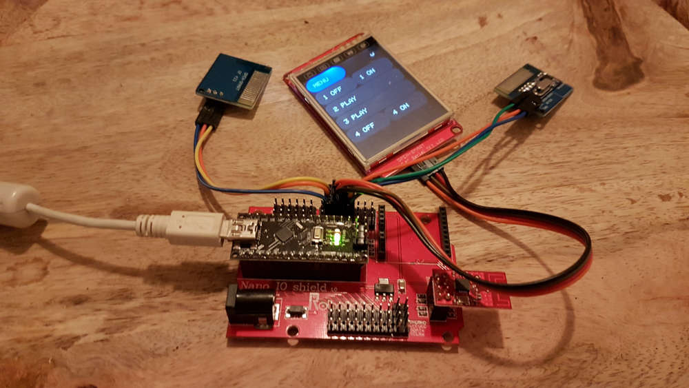
My actual project is a doorbell sensor with additional temperature and humidity sensors. Tried different ways to detect the ring:
- hall sensor (failed)
- microphone (FFT, ongoing research)
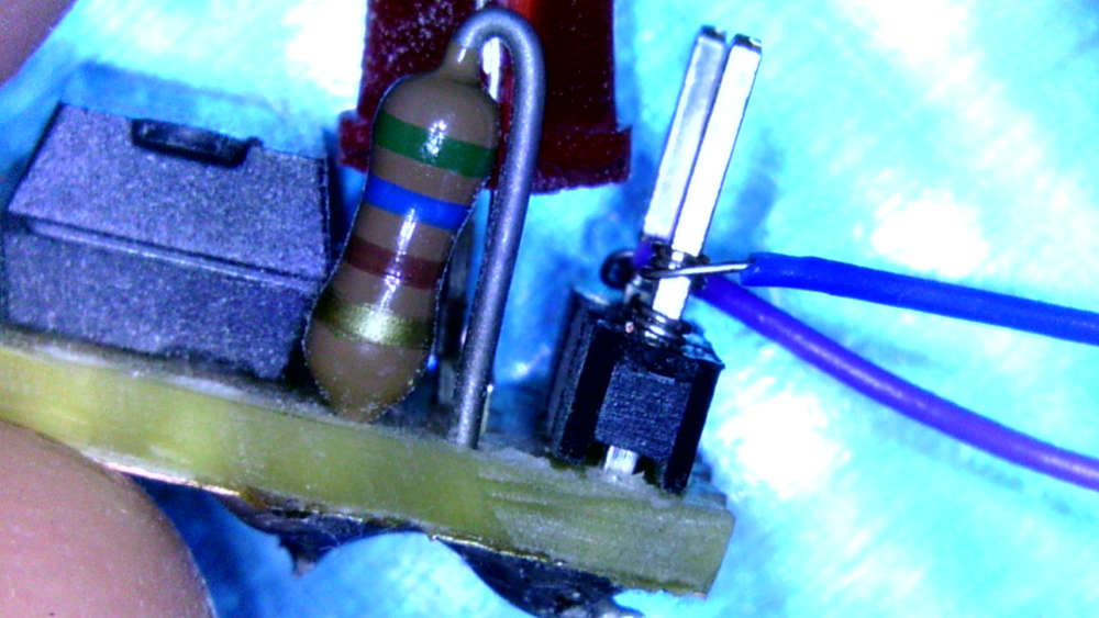
- optocoupler to detect the 12V AC -> favorite solution
As I was heavy prototyping, I tried wire wrapping and it is fun:
-
That looks awesome @alexsh1!
Nicely laid out and cleanly soldered. Was that with an iron or hot air (or both)? Nice clear silk too; I like the power and “signal” symbols. Did you ever try a FOTA update with it? Or a low power/speed profile?
I see you went a bit wider and longer than the standard Pro Mini, (I’m assuming) to get at all the pins and add the extra regulator, LEDs, etc.
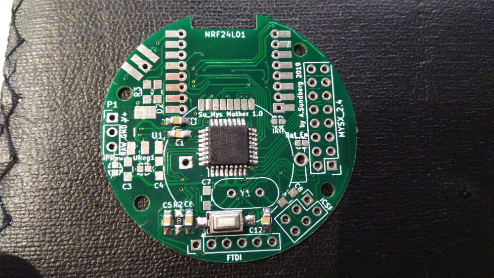
I was constrained by needing something that fit the same footprint for existing boards I already had, e.g. other “motherboards” I’d made similar to @sundberg84’s excellent Easy/Newbie PCB or wanting pin-compatibility for stacking boards like the ATSHA+EEPROM+Radio+ICSP one below:
I tried routing with the chip at a 45 degree angle too but couldn’t get a DRC to pass with the pads so close to the PTHs. I may try again with shorter (custom) TQFP pads...
Re: 1284p’s downsides of cost and size.
I know. I ended up justifying it to myself this way:
We can all get cheap 328p Pro Minis from Ali for around $2. The vast majority of my Pro Mini projects are battery powered, so there’s some “labor cost” to disable the power LED and remove the regulator. But regardless, I certainly can’t make myself a low(er) power Pro Mini for $2 - the OSH Park PCB alone is probably close to that.
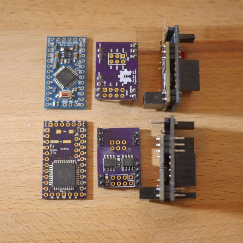
I think the cheapest I ever got 1284p chips for was around $2.50, again from Ali. My “Pro Mini XL” PCBs were around $1.70 from OSH Park, add a sprinkling of 0402s, etc. and we’re probably at around $5.
I couldn’t find any 1284p-based boards near that price. The closest I got was Kevin’s Mini Duino, which is another lovely looking board, but doesn’t fit my need for a Pro Mini-constrained size and pin-compatibility. Essentially, I was after something close to a drop-in replacement.
So, $2+ versus $5+ for all the benefits (at least as far as I was concerned) listed above? It became a bit of a no-brainer.
And on the low power front, I profiled the MySensors library sleep command on it at around 5uA on 4.5v @ 20MHz using an external full swing, around 4uA on 3v @ 8MHz and around 3uA on 1.8v @ 1MHz Internal RC Osc:
Those numbers are certainly good enough for all my current applications - no pun intended! ;)
But I would like to look at the 32-bit contenders as potential replacements.
I’ve seen nRF52s with 512K for around $2 on Ali, so maybe I’ll try my hand at a Pro Mini nRF52 or something similar eventually. The board above was a fun challenge, and afterall is what this is (mainly) about for me.
@acb Hot air has been used for soldering the board. I have not tried low power as I did not build this board for a battery sensor. My board has got two LEDs - power and another LED connected to D0 so clearly not very low power. I also have a 16Mhz firmware. I did not have any size limitation either. I have one particular node with a few sensors and with signing I cannot upload the sketch onto ATMEGA328P as it is marginally larger. Having said that I have not spent too much time optimising the sketch. I think that refactoring libraries, you are fine with ATMEGA328P in 98% of all MySensors applications.
BTW - this is not my project. I have followed it https://github.com/peekpt/mightyduinoRe cost. I stopped Ali shopping for ICs and other sensitive components some time ago after purchasing some fake ATMEGA328P and wasting so many hours trying to troubleshoot it. There is a post about it here on MySensors forum. Ever since I order all components on digi-key. 1284p is priced around $5 + 20% VAT. 328P is priced at $1.2 + VAT. However, I can also buy ATSAMD21 for $2.2 + VAT. Do you see my point? 1284p is extremely expensive and yet it is still 8 bit processor. That's why for me it was a one-off board.
Re sleeping
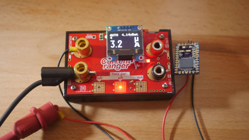
I am using TPL5110 which I built myself (similar to Adafruit one).
Check out sleeping current:
Sadly, I struggled to get some sensors to sleep properly - probably lack of my programming skills - and with a sleeping current being hundreds of uA, I had to resort to this trick. Most of the time, the node
sleepsis disconnected from power by TPL5110 then timer is up and it powers up, sends all sensors readings to the GW and then power gets disconnected to the node, only TPL5110 goes to nA sleep. Perfect! -
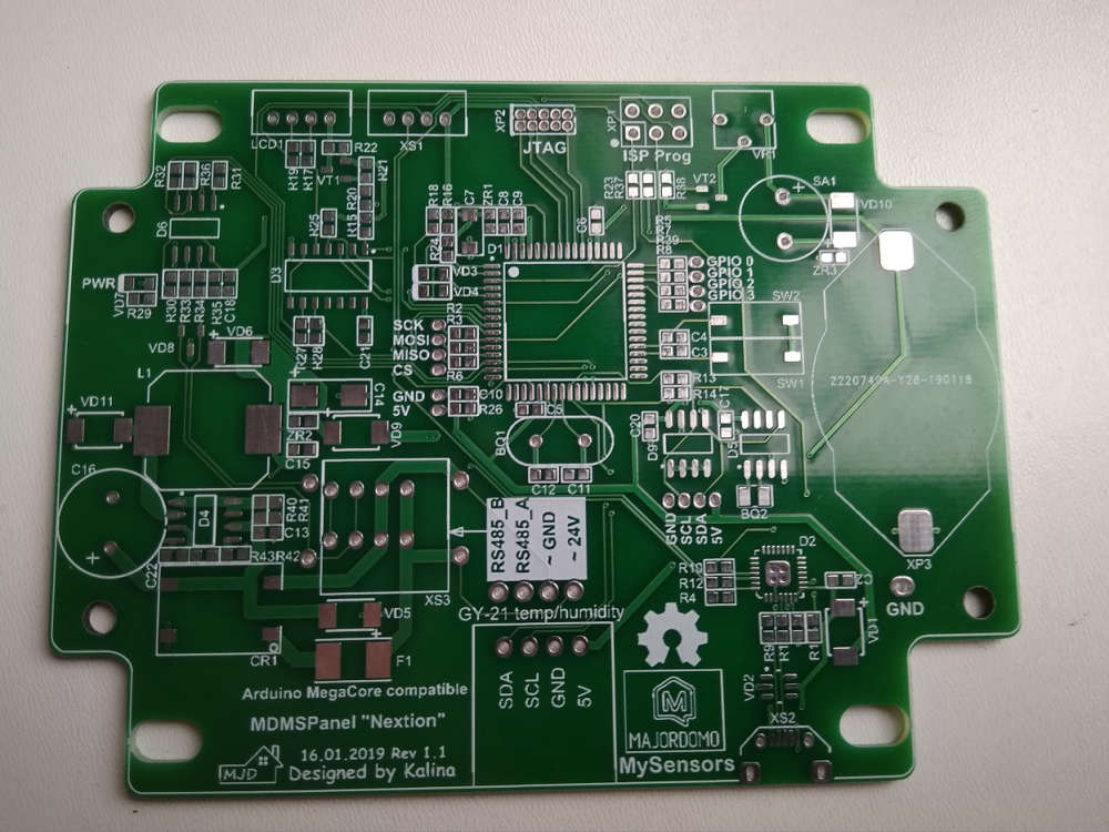
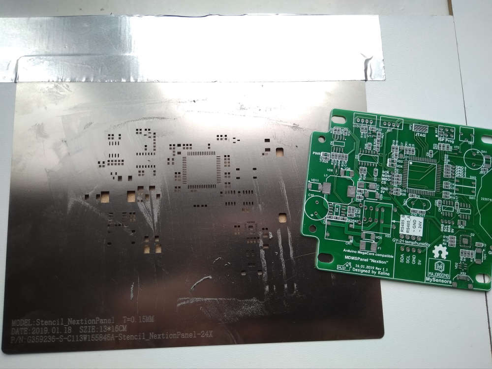
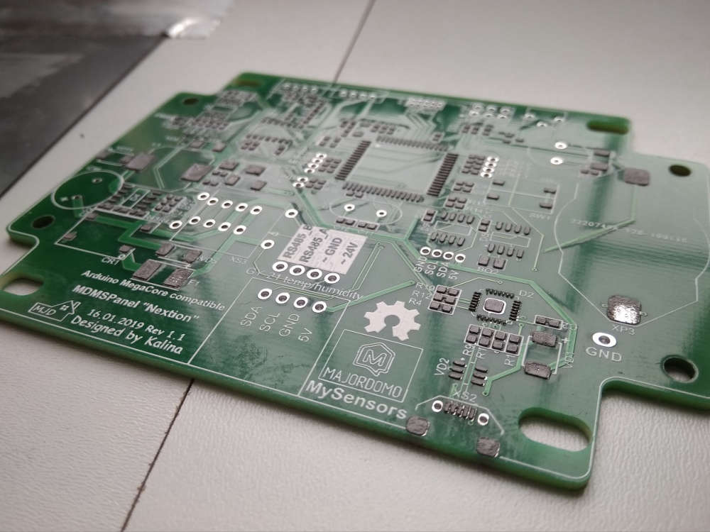
Some photos of my new device - MDMSPanel "Nextion". I have finished soldering an hour ago)) Next week i will public this project.
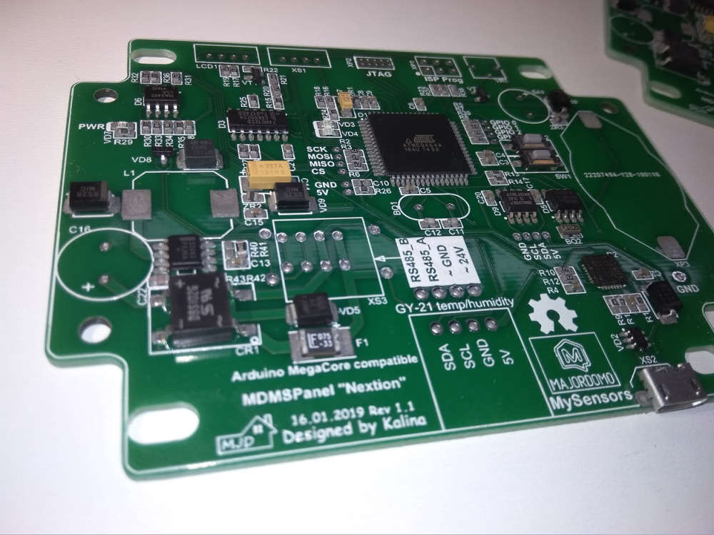
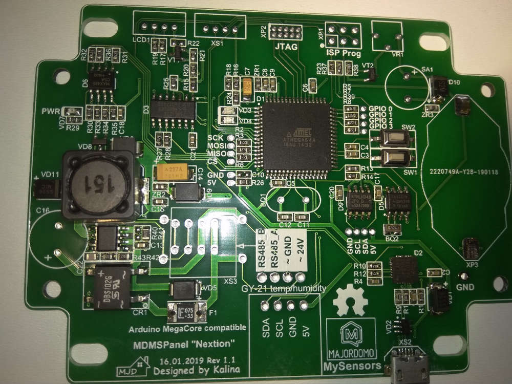
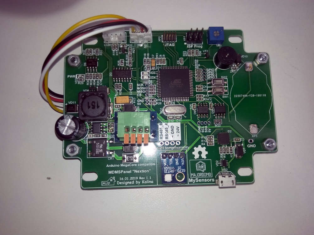
-
@kalina scene controller? I have almost finished mine on Nextion, but do not have time to tidy things up.
-
@monte
Well now Kalina already uses 2 layer PCB, so to improve current 2-layer PCB with ground planes are strongly advised.
Yes 4 layer is naturally much better, but is it needed for a "commodity" device? I think not, and it will increase PCB cost...If you don't have a GND and power planes, you will most likely have power spikes when an IC needs current, this will introduce a magnetic field that will "disturb" especially sensitive analogue tracks and clock signals
-
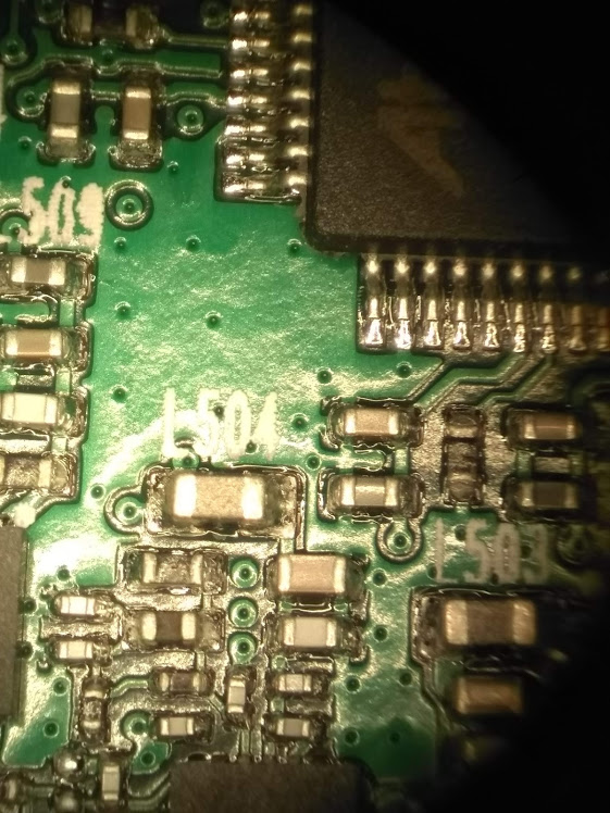
@bjacobse but it actually seems that he HAS a ground plane on one side of PCB, if you look closer at the third photo ;)
-
My actual project is a doorbell sensor with additional temperature and humidity sensors. Tried different ways to detect the ring:
- hall sensor (failed)
- microphone (FFT, ongoing research)
- optocoupler to detect the 12V AC -> favorite solution
As I was heavy prototyping, I tried wire wrapping and it is fun:
@fotofieber
Wirewrapping is an "old" and well proven technology, remember to have extra cable in case you need to re-wire your cables. Not so popular by DIY as tools used to be fairly expensive as it was protected by patents... -
@bjacobse
Just to add a little more info about adding a GND plane to your PCB
I work in a electronic company, not doing PCB layout there though.
but we have a TV adapter which have 2.4GHz transmitter. and this PCB is GND on both sides and with plenty GND via's (all the small holes) to ensure good grounding
In case you wonder what it is, then it's an Oticon TV adapter 3.0
https://www.youtube.com/watch?v=r4bTIQPdCEo -
-
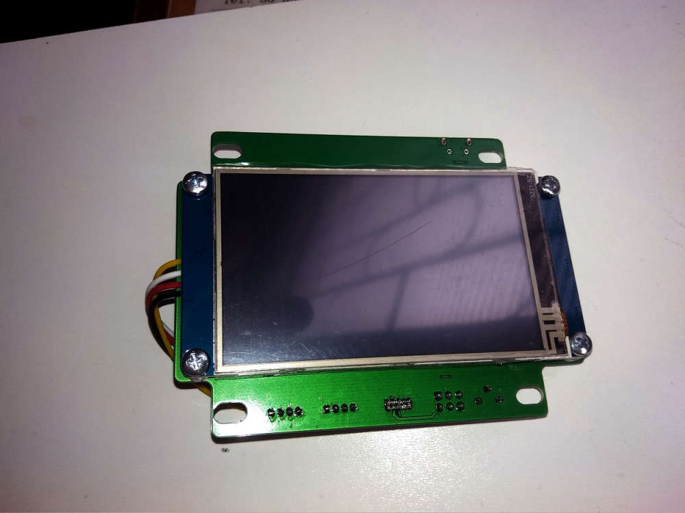
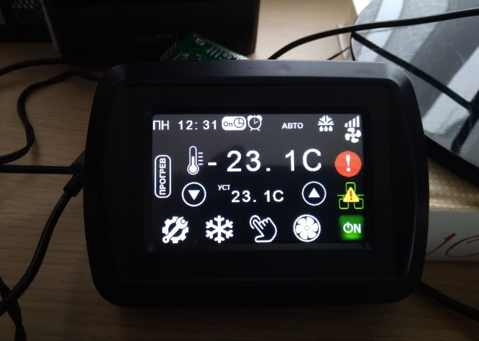
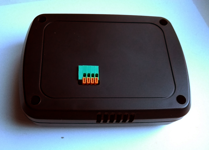
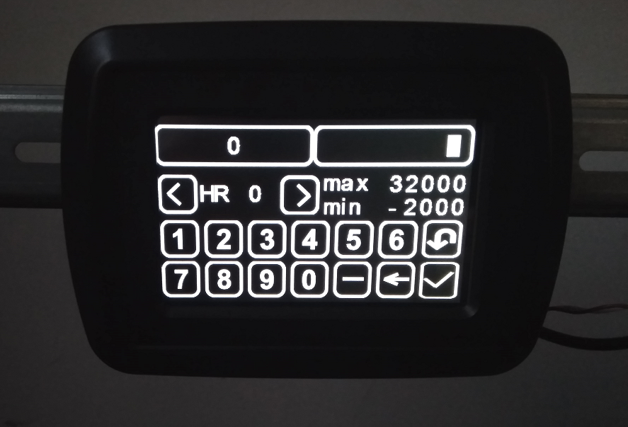
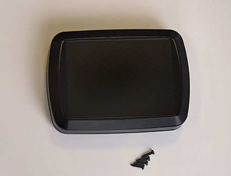
I have finished an enclosure for the my MDMSPanel "Nextion" today.
-
Wow, very cool! Can you share a bit more about the project? Is it MySensors based? Is there code available? What does the hardware inside look like? What processor is it base on?
Ah, scrolling up answered some of my questions :-)
-
Wow, very cool! Can you share a bit more about the project? Is it MySensors based? Is there code available? What does the hardware inside look like? What processor is it base on?
Ah, scrolling up answered some of my questions :-)
-
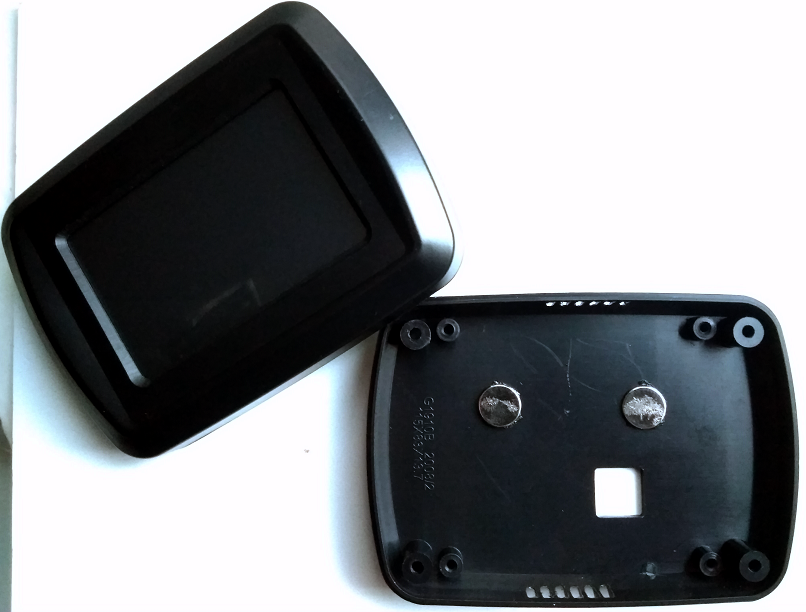
@kalina Kudos on the case. Is that a case you designed, or is it a prefab case that you bought somewhere? I am assuming that from the markings inside the case that it is a prefab.I do like the design though and love it's underlying project. Is that just a thermostat, or is it a multi option controller?
Vera Plus running UI7 with MySensors, Sonoffs and 1-Wire devices
Visit my website for more Bits, Bytes and Ramblings from me: http://dan.bemowski.info/ -
@kalina Kudos on the case. Is that a case you designed, or is it a prefab case that you bought somewhere? I am assuming that from the markings inside the case that it is a prefab.I do like the design though and love it's underlying project. Is that just a thermostat, or is it a multi option controller?
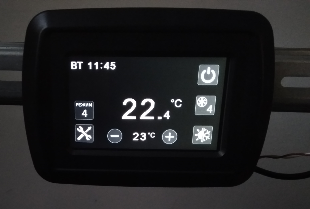
@dbemowsk Yes, it is a factory case, and before the changing it looked like this :
At the moment this is termostat, but I will not limit myself to this)) The purpose of the panel will be determined by the software project loaded into it. I will describe this in more detail when I publish the project.
-
@bjacobse said in What did you build today (Pictures) ?:
Yes it's very impressing what you have achieved
Thanks, the project is published already.
-
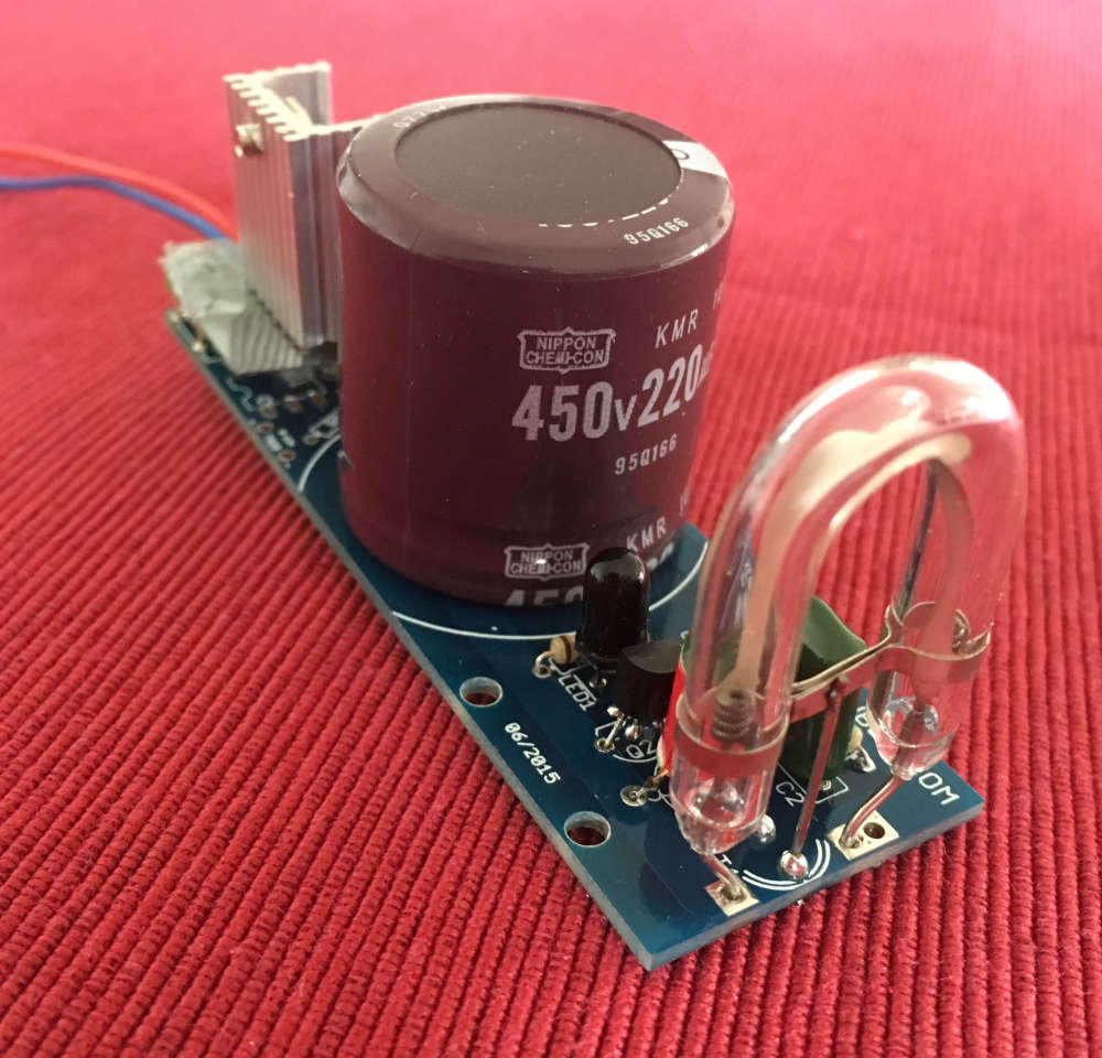
Building a (xenon) flash to notify alarms. Flashes every 5 seconds if activated.
-
-
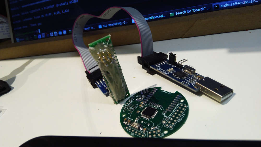
Today I made a iscp pogo pin adapter... Great for uploading bootloaders.