What did you build today (Pictures) ?

-
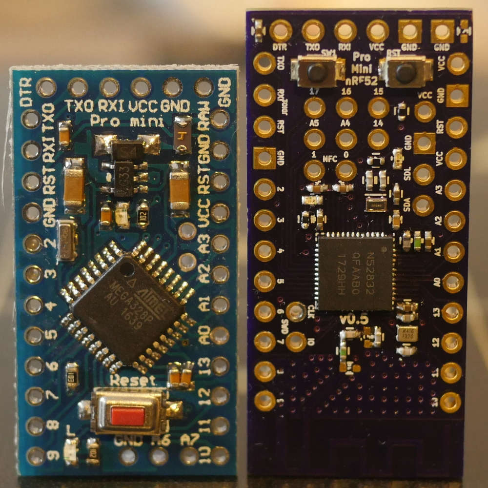
Continuing along the theme of one of my last projects, I built a nRF52832 into a 328p Pro Mini footprint. Made two versions: One with some edge SMA or U.Fl pads and another with a PCB trace antenna:
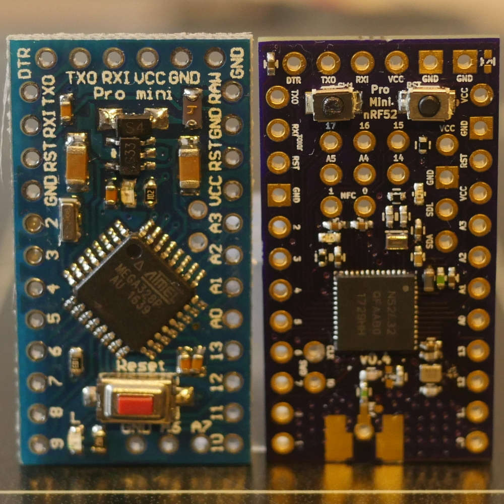
I wanted to start getting into using 32-bit microcontrollers (ARM Cortex varieties like nRF5x, SAMDs, STMs, etc.) for some more complex HA and other electronics projects and am trying to ease the learning curve from all my 8-bit ATMEGA experience.
Keeping the 328p pin-compatible footprint and PCB size means I can still reuse most of my other Pro Mini project boards to get going. An added bonus is the nRF52's ability to remap (almost) any pins, which will no doubt come in handy.
They’re both two layer boards and I get pretty decent range out of the PCB trace antenna - ever so slightly better RSSI than EByte’s E73-2G4M04S1B, which was surprising since I didn’t really do anything different (that I’m aware of) and their module is shielded too.
Since there’s no need for a separate nRF24 board and other associated components, like external SRAM or ATSHA, it’ll possibly save me a few $ too! Power pins next to the (remappable) I2C pins make some of the sensor modules (like SI7021) pluggable.
I also gain 16x the program memory (512K vs. 32K) and 8x the speed (64MHz vs. 8MHz) which is no small increment!
Some of the project boards I have made use of the Pro Mini 328p’s FTDI pins, so I added a few components to enable the use of an FTDI programmer with custom DFU serial bootloader.
Basically, a DTR pin toggle from the FTDI will reset the nRF52 into a state where it’ll briefly listen for a new program - similar to Adafruit’s Feather. You can also force that state for a longer period with a combination button press like Nordic and SparkFun’s development boards.
I’m unfamiliar with SWD/JTAG programming/debugging and all things GDB/OCD, so I built myself a black magic probe out of a STM32 blue pill and am going to have a play with all of that, along with VS Code and PlatformIO and probably one or two others.
MySensors nRF52 support worked out of the box (!) - so a huge thanks to all the hard work of the folks round here for getting that up and running. If there’s anything I can help with there, please let me know and if I’m able, I’ll try to take a stab at it (OTA maybe?). Like I said, I’ve got quite a steep learning curve here though.
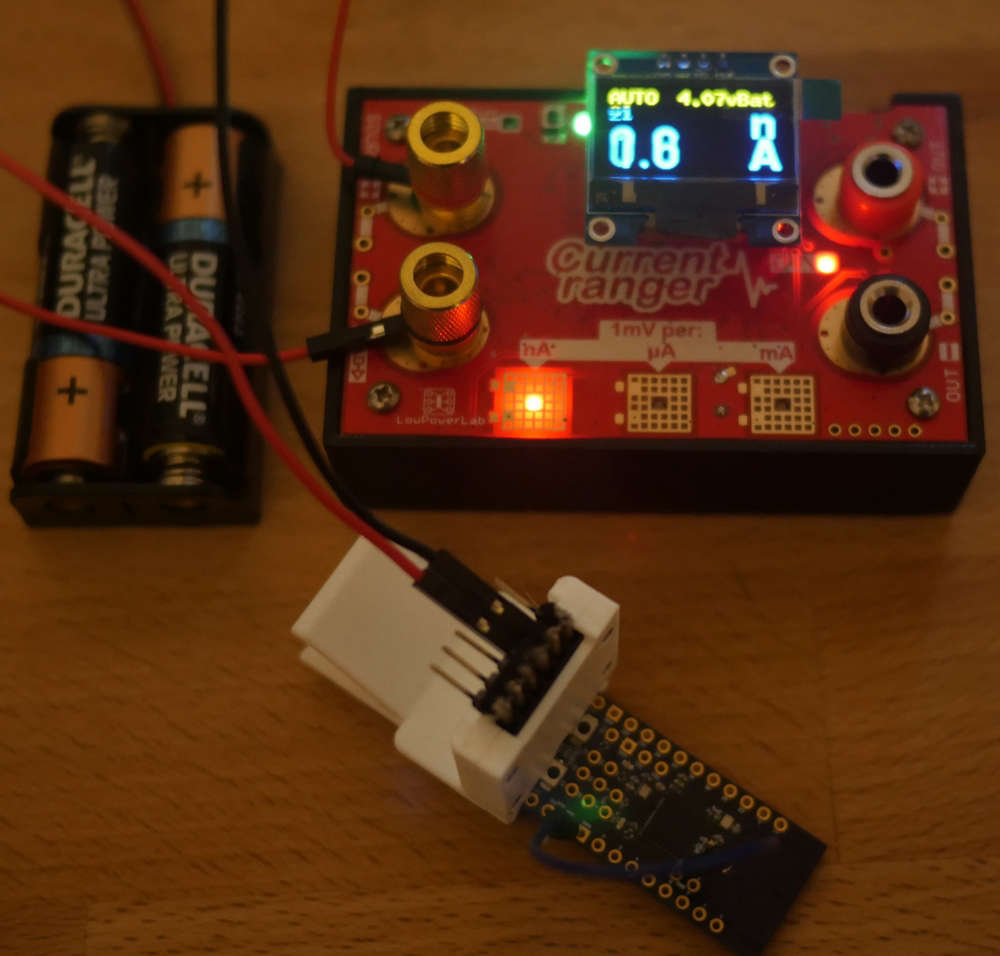
On the low power end, I added the DCDC components Nordic recommend too and managed to get the MySensors smartSleep() current down to around 0.7uA - as per the datasheet, I think. However, I found that with a couple more code tweaks and grounding the SWDCLK, I would get into the nA region. This seems a bit out of spec to me and perhaps it’s just a measuring error, but it was repeatable and the board still happily sending data/heartbeat again each time it woke up. (It’s fluctuating around 1.6nA below - no sensors connected though, but it’s a start…)
One other project in the back of my mind is using this board as the basis for a quadcopter, but that’ll probably have to wait until the summer holidays…!
-
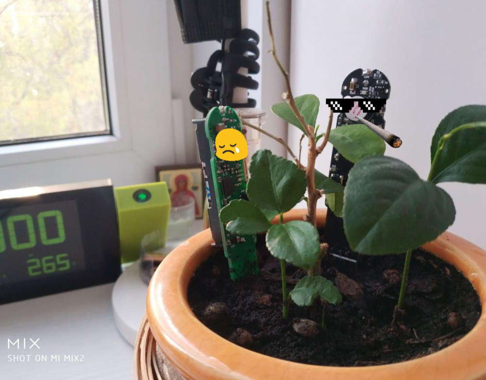
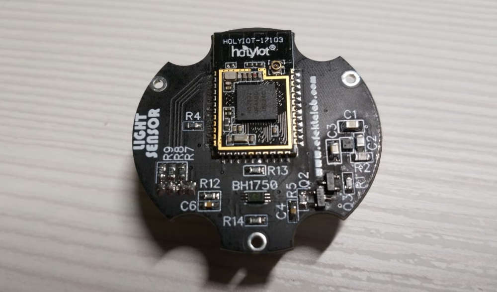
My light sensor on the window. Will work as a slave device for the curtain controller.
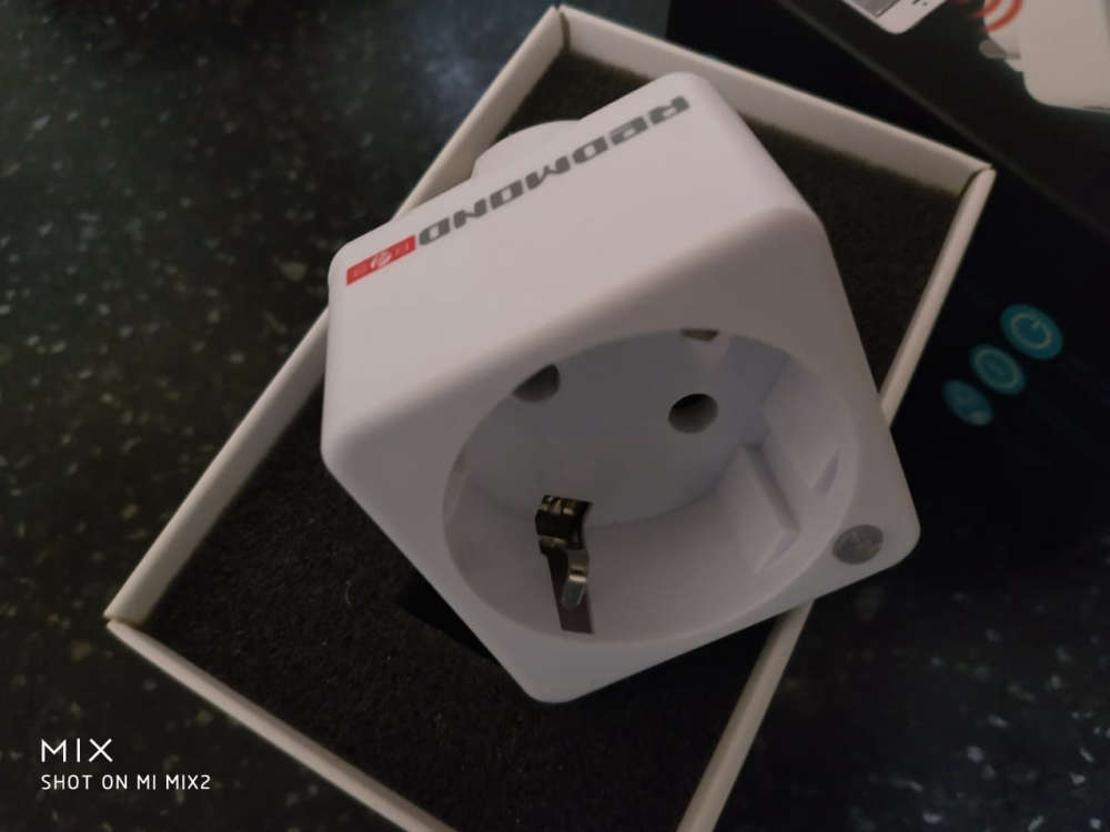
-
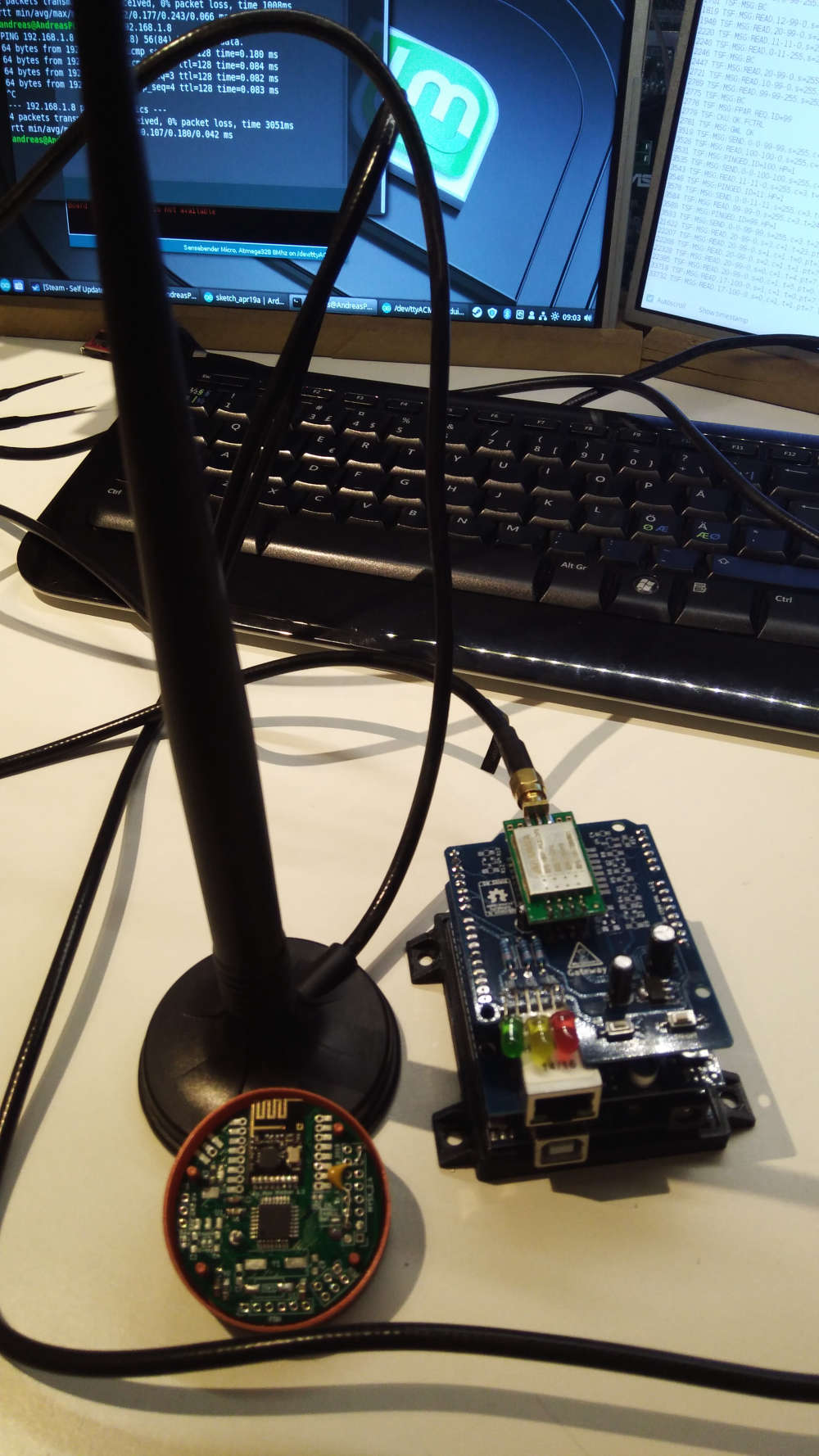
New gateway going live and migrating slowly from Domoticz to Homeassistant. At least to try it.
-
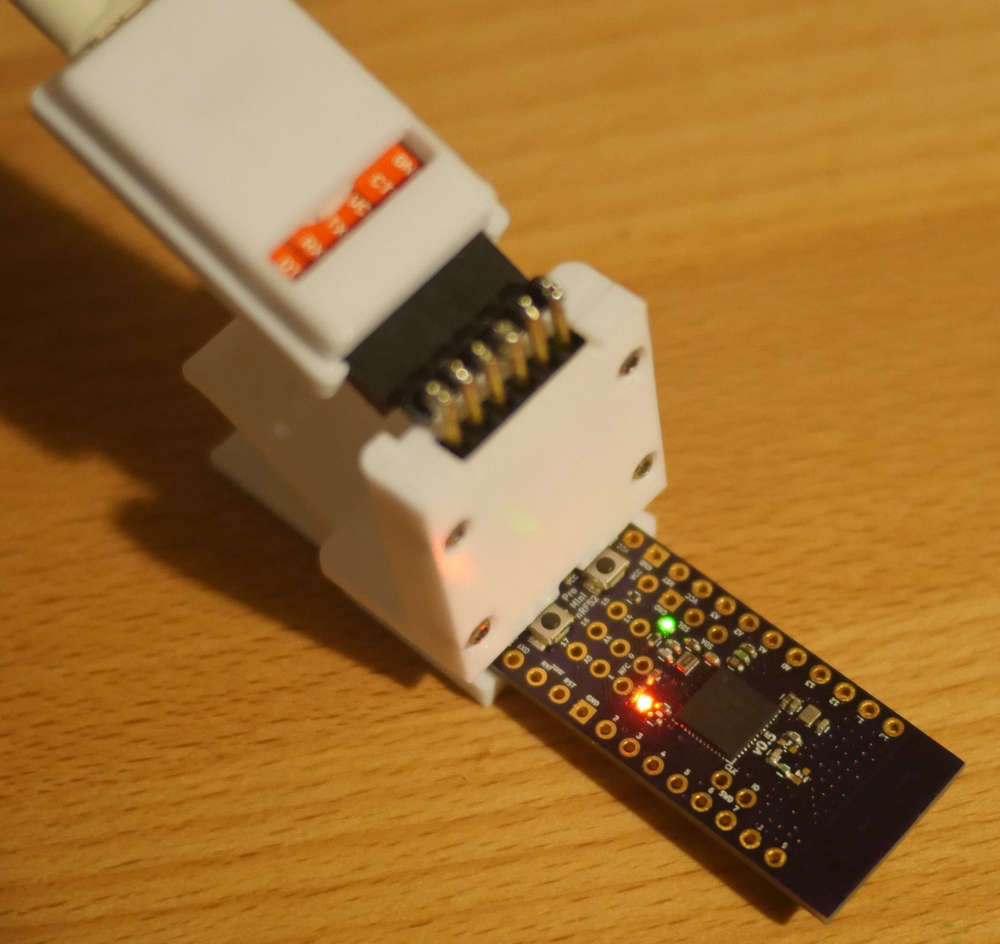
@nagelc Thanks! The clip on programmer is one-part Adafruit’s FTDI “Fiddy” from here, and one-part SparkFun’s old (retired?) 3.3 or 5v selectable FTDI programmer with a custom 3D printed enclosure.
I plan to modify the “Fiddy” design a bit as there were some elements of it that I’ve found a bit frustrating. However, YMMV. Gotta love pogo pins for programming though…
Re: Board envy. Really? Well, if you like, I could do what I did on my last project - which was selling the leftovers. At the moment, I always make more than I need, for testing and some much needed practice with the smaller 0402s. Just send me a chat message if you (or anyone else?) are interested.
-
@acb have you written a bootloader yourself, or found already available? Can you tell more about it and a board you using to connect nrf52 to FTDI?
Nice work!@monte Re: FTDI Boards & Bootloaders.
I didn’t write the bootloader myself from scratch, but modified and combined various elements from Nordic’s SDK v11 example, SparkFun’s development version and Adafruit’s Feather version.
It was quite a nice learning experience of hacking in bootloader land and dealing with event-driven architectures without any low level debugging skills (yet!) - that’s why I’m now trying to get into SWD/JTAG debugging to make things like this easier.
I certainly don’t understand everything that’s going on, but “loosely” from what I can figure out, it uses Nordic’s proprietary SoftDevice (S132) combined with some custom bootloader code to boot into a predefined state, where it’ll wait for new “image” either over a serial or bluetooth connection.
The new “image” can be either your regular sketch-type code (referred to as the “application”), a new SoftDevice (S212, S332, etc.) and/or even a new bootloader.
Once the new “image” is received and validated by the (existing) bootloader, it is copied to replace the existing “image” parts where necessary and the chip is reset.
Nordic’s pc-nrfutil command line utility handles interfacing with any standard FTDI board over a COM port (mine is an old SparkFun, but any should work) to perform the upload.
In SDK11, there isn’t much in the way of safeguards, but in SDK15 there are things like cryptographic signing, custom initialization packets and protocol buffers, etc.
I did have to make one tweak to the nrfutil Python code, to make it wait a little longer after opening the COM port before sending the DFU initialization packet. This might be unnecessary with optimized bootloader code, I don’t know, since the nRF52832 boots pretty quickly.
I could go on, but I’m still learning myself, and so if you or anyone else has any other questions, comments, suggestions, etc., perhaps we better move them to a new discussion thread? (Just tag me in so I see it…)
Thanks for your interest though!
-
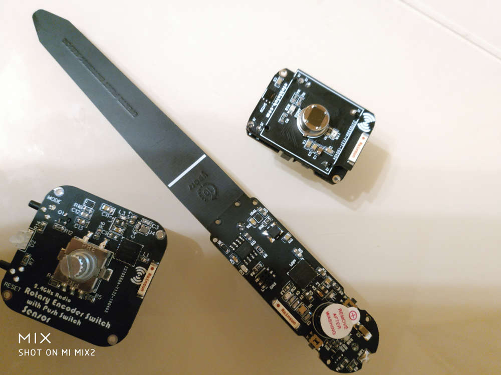
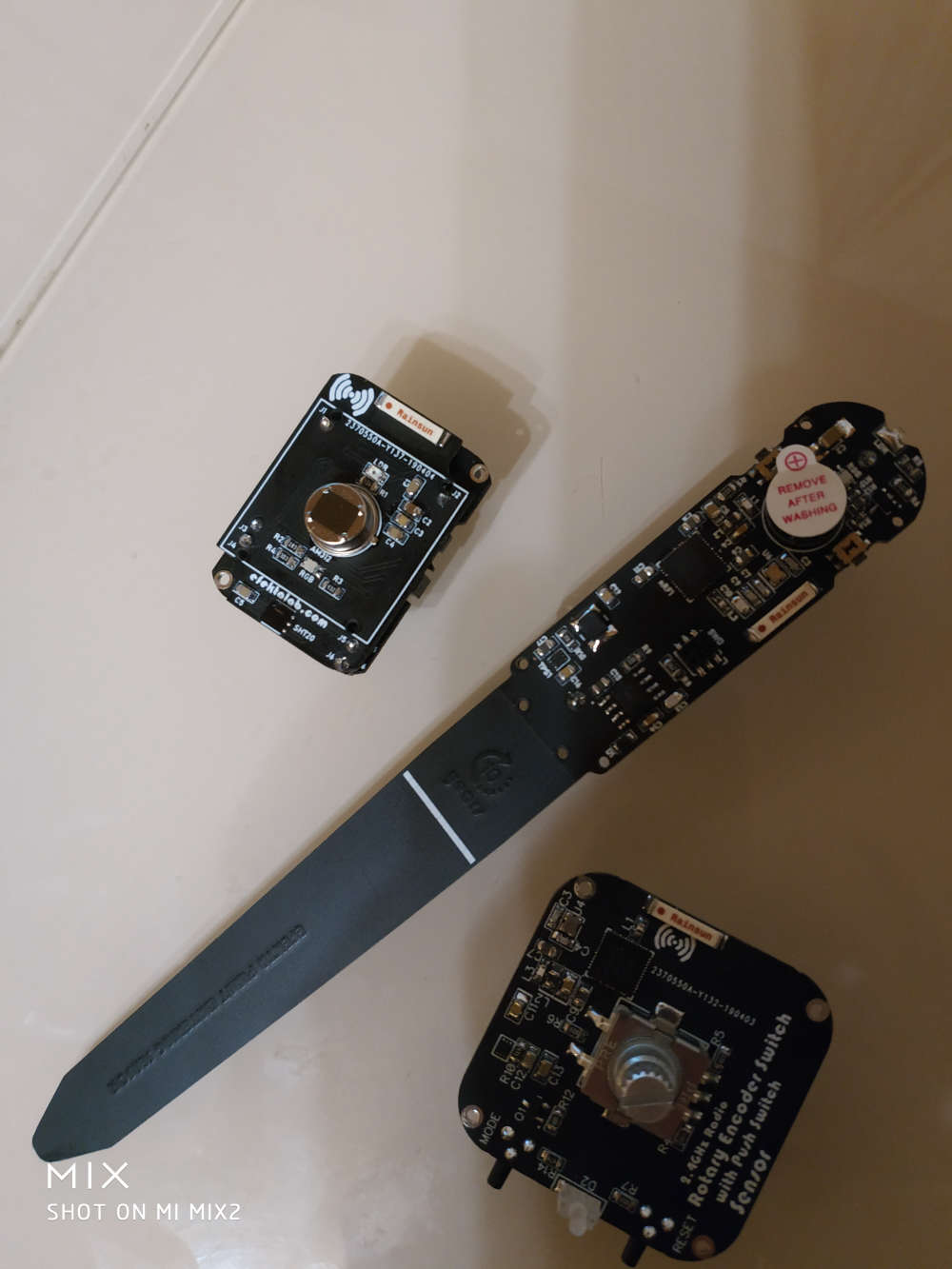
Well,in my case, I mounted and tried to fix bugs in my very first design. This is supposed to be a castelizable Sensebender compatible node, embedding NRF24L01+, LED, Temp/Humi/Press sensor, Memory, crypto, with most of the IO exposed. The updated design is online, but still work in progress.
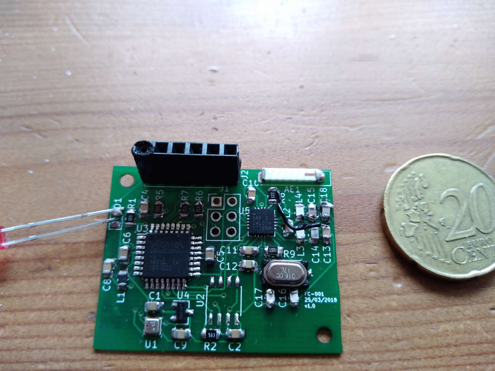
project on OpenHardware -
Thanks @berkseo!
Have been enjoying your work with nRF52 designs.
Also on my list is trying the built-in capacitive touch capabilities of the chip.
I can @ you if I get anywhere with it - might come in handy for your capacitive touch glass mini switch to save you a few components?
-
Thanks @berkseo!
Have been enjoying your work with nRF52 designs.
Also on my list is trying the built-in capacitive touch capabilities of the chip.
I can @ you if I get anywhere with it - might come in handy for your capacitive touch glass mini switch to save you a few components?
-
@monte Re: FTDI Boards & Bootloaders.
I didn’t write the bootloader myself from scratch, but modified and combined various elements from Nordic’s SDK v11 example, SparkFun’s development version and Adafruit’s Feather version.
It was quite a nice learning experience of hacking in bootloader land and dealing with event-driven architectures without any low level debugging skills (yet!) - that’s why I’m now trying to get into SWD/JTAG debugging to make things like this easier.
I certainly don’t understand everything that’s going on, but “loosely” from what I can figure out, it uses Nordic’s proprietary SoftDevice (S132) combined with some custom bootloader code to boot into a predefined state, where it’ll wait for new “image” either over a serial or bluetooth connection.
The new “image” can be either your regular sketch-type code (referred to as the “application”), a new SoftDevice (S212, S332, etc.) and/or even a new bootloader.
Once the new “image” is received and validated by the (existing) bootloader, it is copied to replace the existing “image” parts where necessary and the chip is reset.
Nordic’s pc-nrfutil command line utility handles interfacing with any standard FTDI board over a COM port (mine is an old SparkFun, but any should work) to perform the upload.
In SDK11, there isn’t much in the way of safeguards, but in SDK15 there are things like cryptographic signing, custom initialization packets and protocol buffers, etc.
I did have to make one tweak to the nrfutil Python code, to make it wait a little longer after opening the COM port before sending the DFU initialization packet. This might be unnecessary with optimized bootloader code, I don’t know, since the nRF52832 boots pretty quickly.
I could go on, but I’m still learning myself, and so if you or anyone else has any other questions, comments, suggestions, etc., perhaps we better move them to a new discussion thread? (Just tag me in so I see it…)
Thanks for your interest though!
@acb we can continue discussion in this thread, If you want: https://forum.mysensors.org/topic/6961/nrf5-action/
So as I understand for now you are using native SDK and not using Arduino and mysensors? As far as I know arduino's core for nrf5 has no support for bootloaders, and mysensors conflicts even with softdevice being present on a chip. And it seems that sandeepmistry (author of the core) isn't going to invest his time into writing bootloader and can't use nordic's one because of license. I would like to have a bootloader solely for bluetooth OTA programming for projects beside mysensors. Maybe you could share your work, and/or write some kind of brief tutorial on where to start working on this subject maybe to avoid problems you have already solved? Anyway, great work from you, hope someday we will have mysensors on nrf52 with working OTA.
-
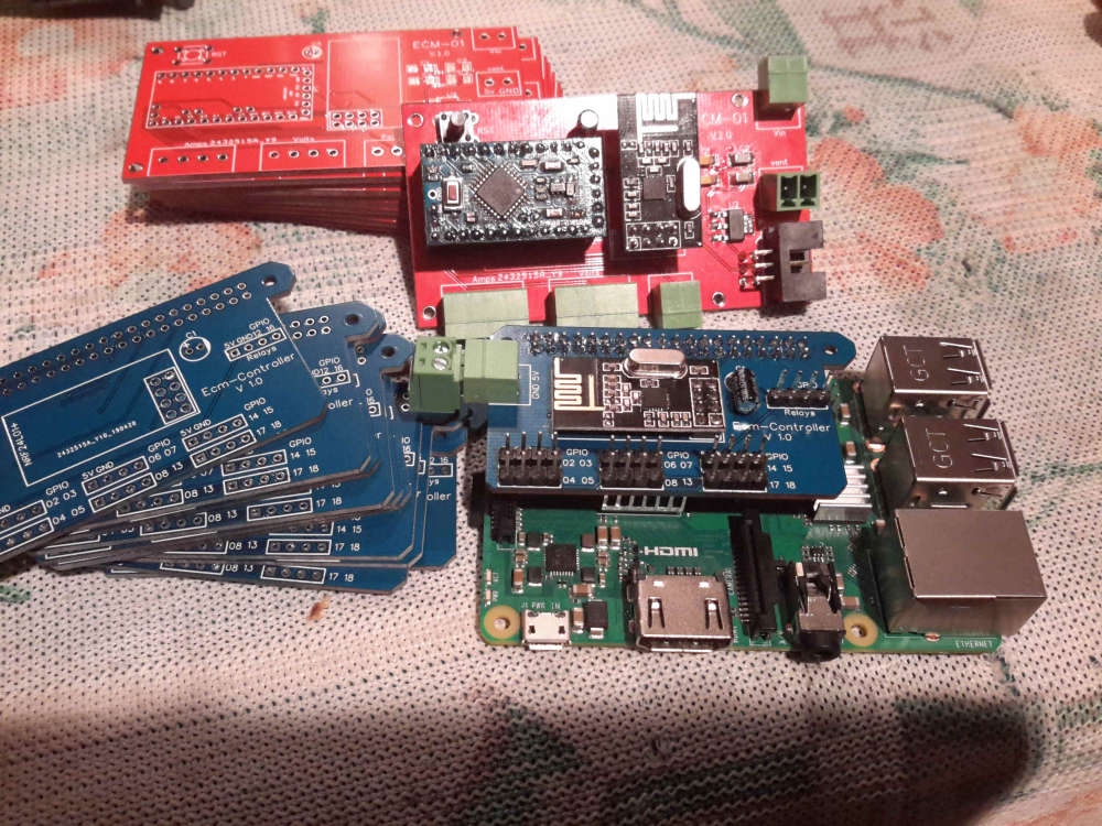
well this is my project , right now im using 2 arduino nano with ethernet shield to read 3 lines Voltage on a delta instalation , 3 current sensors of 300amps for a motor , and 1 water pressure ,
all conected to a raspberry pi with domoticz
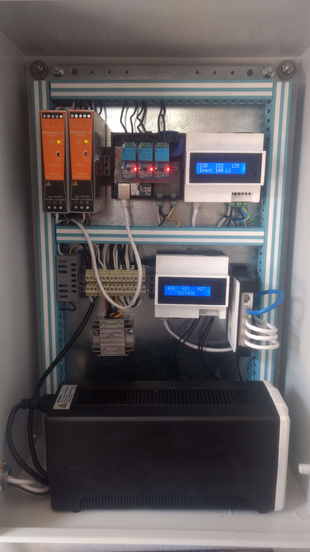
but yesterday i decide to change all , instead of 2 uno i will use a pro mini with a nrf24
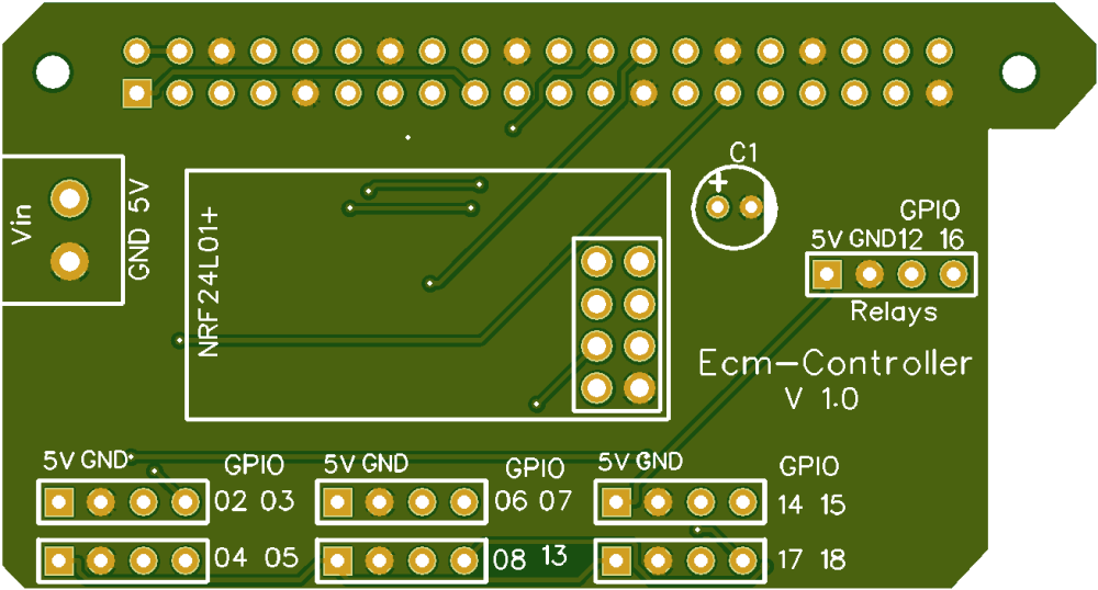
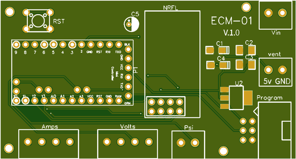
so i desing two pcb
some code
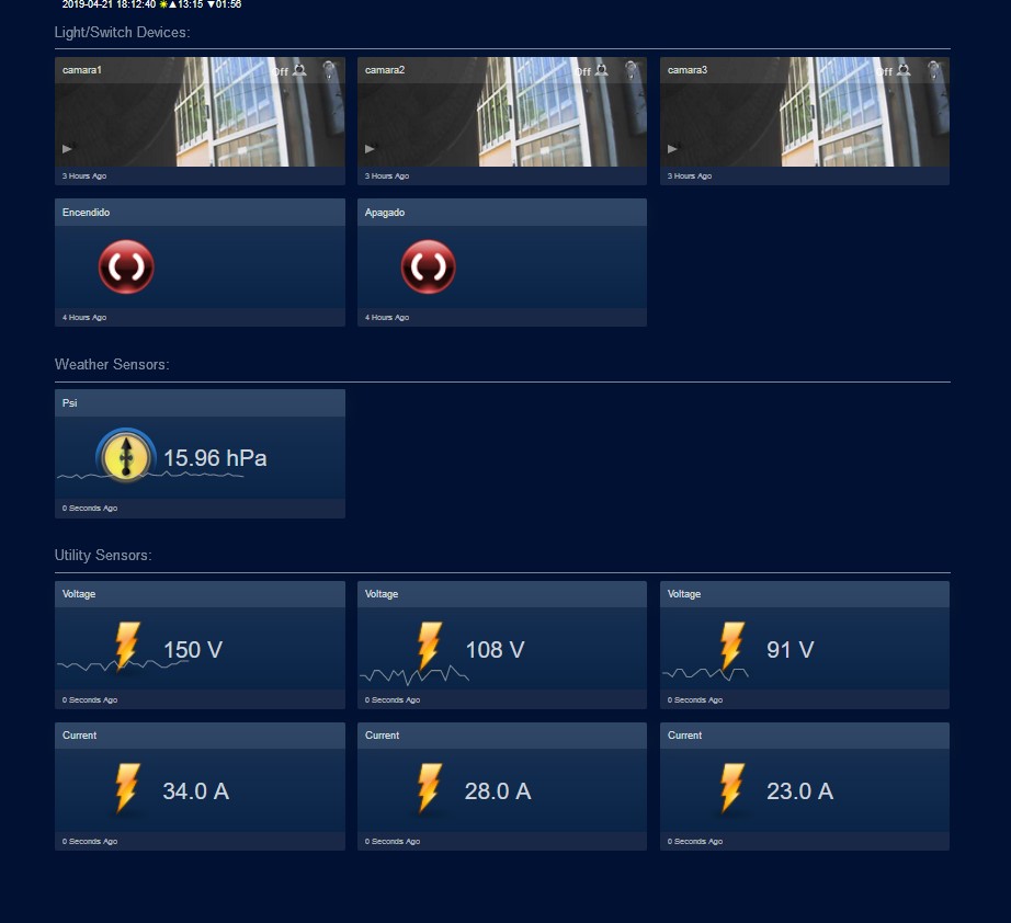
#define MY_NODE_ID 100
#define MY_DEBUG
#define MY_RADIO_NRF24

#include <SPI.h>
#include <MySensors.h>


#define CHILD_ID_VOLT_1 1
#define CHILD_ID_VOLT_2 2
#define CHILD_ID_VOLT_3 3

#define CHILD_ID_CURRENT_1 4
#define CHILD_ID_CURRENT_2 5
#define CHILD_ID_CURRENT_3 6

#define CHILD_ID_PRESION 7

#define VOLT_SENSOR_ANALOG_PIN_1 0
#define VOLT_SENSOR_ANALOG_PIN_2 1
#define VOLT_SENSOR_ANALOG_PIN_3 2

#define CURRENT_SENSOR_ANALOG_PIN_1 3
#define CURRENT_SENSOR_ANALOG_PIN_2 4
#define CURRENT_SENSOR_ANALOG_PIN_3 5


#define PressPin      A6


unsigned long SLEEP_TIME = 20000; // Sleep time between reads (in milliseconds)

MyMessage msg(CHILD_ID_VOLT_1, V_VOLTAGE);
MyMessage msg2(CHILD_ID_VOLT_2, V_VOLTAGE);
MyMessage msg3(CHILD_ID_VOLT_3, V_VOLTAGE);

MyMessage msg4(CHILD_ID_CURRENT_1, V_CURRENT);
MyMessage msg5(CHILD_ID_CURRENT_2, V_CURRENT);
MyMessage msg6(CHILD_ID_CURRENT_3, V_CURRENT);

MyMessage pressureMsg(CHILD_ID_PRESION, V_PRESSURE);

float lastVolt1;
float lastVolt2;
float lastVolt3;

float lastCurrent1;
float lastCurrent2;
float lastCurrent3;

float lastPresion;


int pressure = 0;
float PSI = 0;
float PSI_CAL = 2.0;            // Calibration of sensor
int PSImsb = 0;
int PSIr = 0;


void before() {

}


void presentation()
{
 sendSketchInfo("Multisensor", "1.7");  // Send the sketch version information to the gateway and Controller
 present(CHILD_ID_VOLT_1, S_MULTIMETER);   // Register this device as power sensor
 present(CHILD_ID_VOLT_2, S_MULTIMETER);   // Register this device as power sensor
 present(CHILD_ID_VOLT_3, S_MULTIMETER);   // Register this device as power sensor

 present(CHILD_ID_CURRENT_1, S_MULTIMETER);   // Register this device as power sensor
 present(CHILD_ID_CURRENT_2, S_MULTIMETER);   // Register this device as power sensor
 present(CHILD_ID_CURRENT_3, S_MULTIMETER);   // Register this device as power sensor

 present(CHILD_ID_PRESION, S_WATER);   // Register this device as power sensor

}


void setup()
{

}

void loop()
{
 int Voltaje1 = analogRead(A0);
 int Voltaje2 = analogRead(A1);
 int Voltaje3 = analogRead(A2);

 int Corriente1 = analogRead(A3);
 int Corriente2 = analogRead(A4);
 int Corriente3 = analogRead(A5);


 float VoltLevel1 = map(Voltaje1,0,1023,0,500);
 float VoltLevel2 = map(Voltaje2,0,1023,0,500);
 float VoltLevel3 = map(Voltaje3,0,1023,0,500);

 float CorrienteLevel1 = map(Corriente1,0,1023,0,200);
 float CorrienteLevel2 = map(Corriente2,0,1023,0,200);
 float CorrienteLevel3 = map(Corriente3,0,1023,0,200);


 Serial.print("Voltaje L1: ");
 Serial.println(VoltLevel1);
 Serial.print("Voltaje L2: ");
 Serial.println(VoltLevel2);
 Serial.print("Voltaje L3: ");
 Serial.println(VoltLevel3);


 Serial.print("Corriente L1: ");
 Serial.println(CorrienteLevel1);
 Serial.print("Corriente L2: ");
 Serial.println(CorrienteLevel2);
 Serial.print("Corriente L3: ");
 Serial.println(CorrienteLevel3);

 //sensor de voltaje
 if (VoltLevel1 != lastVolt1) {
     send(msg.set(VoltLevel1, 1));
     lastVolt1 = VoltLevel1;
 }

   if (VoltLevel2 != lastVolt2) {
     send(msg2.set(VoltLevel2, 1));
     lastVolt2 = VoltLevel2;
 }
   if (VoltLevel3 != lastVolt3) {
     send(msg3.set(VoltLevel3, 1));
     lastVolt3 = VoltLevel3;
 }


//sensor de corriente
   if (CorrienteLevel1 != lastCurrent1) {
     send(msg4.set(CorrienteLevel1, 1));
     lastCurrent1 = CorrienteLevel1;
 }
     if (CorrienteLevel2 != lastCurrent2) {
     send(msg5.set(CorrienteLevel2, 1));
     lastCurrent2 = CorrienteLevel2;
 }
     if (CorrienteLevel3 != lastCurrent3) {
     send(msg6.set(CorrienteLevel3, 1));
     lastCurrent3 = CorrienteLevel3;
 }

/* ************************************************ */
   pressure  = analogRead    (PressPin) ;        // junk read
   wait(25);

/* • Output: 0.5V – 4.5V linear voltage output. 0 psi outputs 0.5V, 50 psi outputs 2.5V, 100 psi outputs 4.5V
   0   psi = .33v after scalling 5.0v to 3.3v
   50  psi = 1.65v
   100 psi = 2.97v

   3.3v/1024 = .0032266 volt per bit
*/
   pressure  = analogRead    (PressPin) ;

   if (pressure < 106) pressure = 106;         // this is minimum of .5v
   PSI = (pressure - 106 ) * .1246;            // where did we get this?? was .119904
   PSI = PSI + PSI_CAL;                        // adjustment

   PSImsb = PSI * 100;
   PSIr = PSImsb % 100;


   send(pressureMsg.set(PSI, 2));            // Send water pressure to gateway

   Serial.print("Presion: ");
   Serial.println(PSI);

   wait(200);

    // end of if (SLEEP_MODE || (cu


 sleep(SLEEP_TIME);
}
havent tested with sensors yet
but looks good so far
-
@berkseo whoa, time for a Kickstarter! They look great! Where did you have them made, and what do they cost?
@fernando-alvarez-buylla Always nice to see the Aurora theme being used :-)
-
And a few days later my pcb's arrived
Now to test the next version
-
-
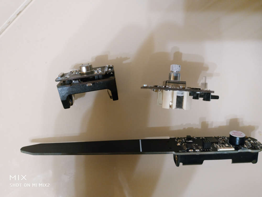
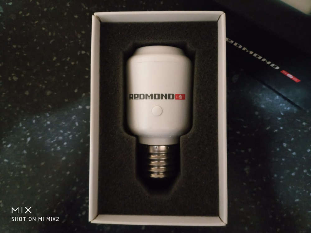
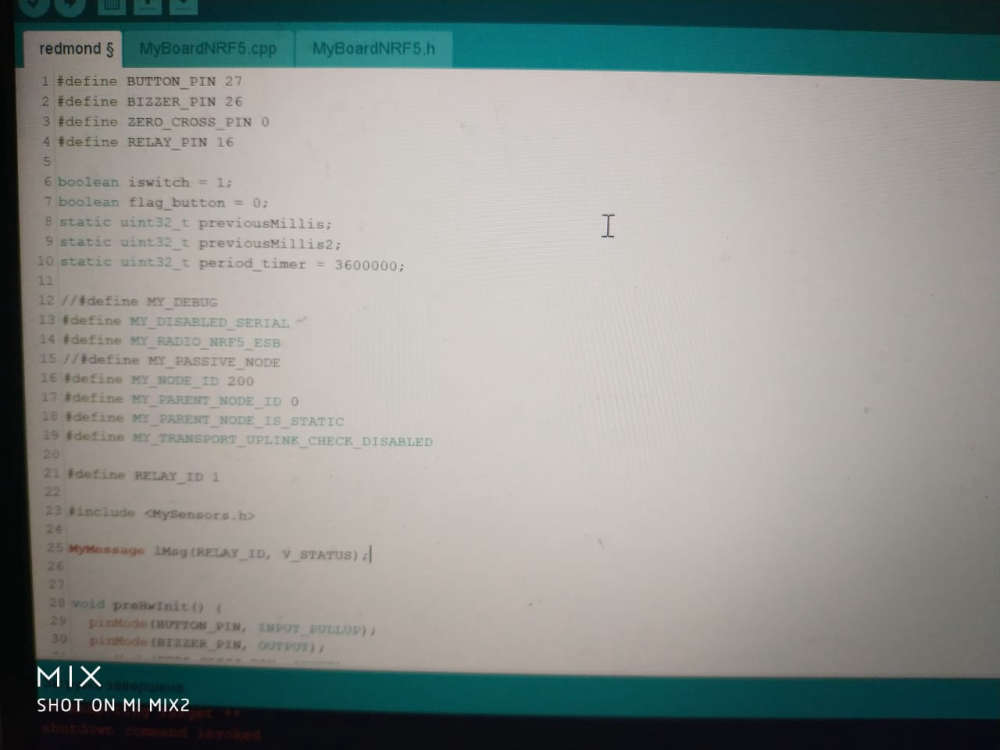
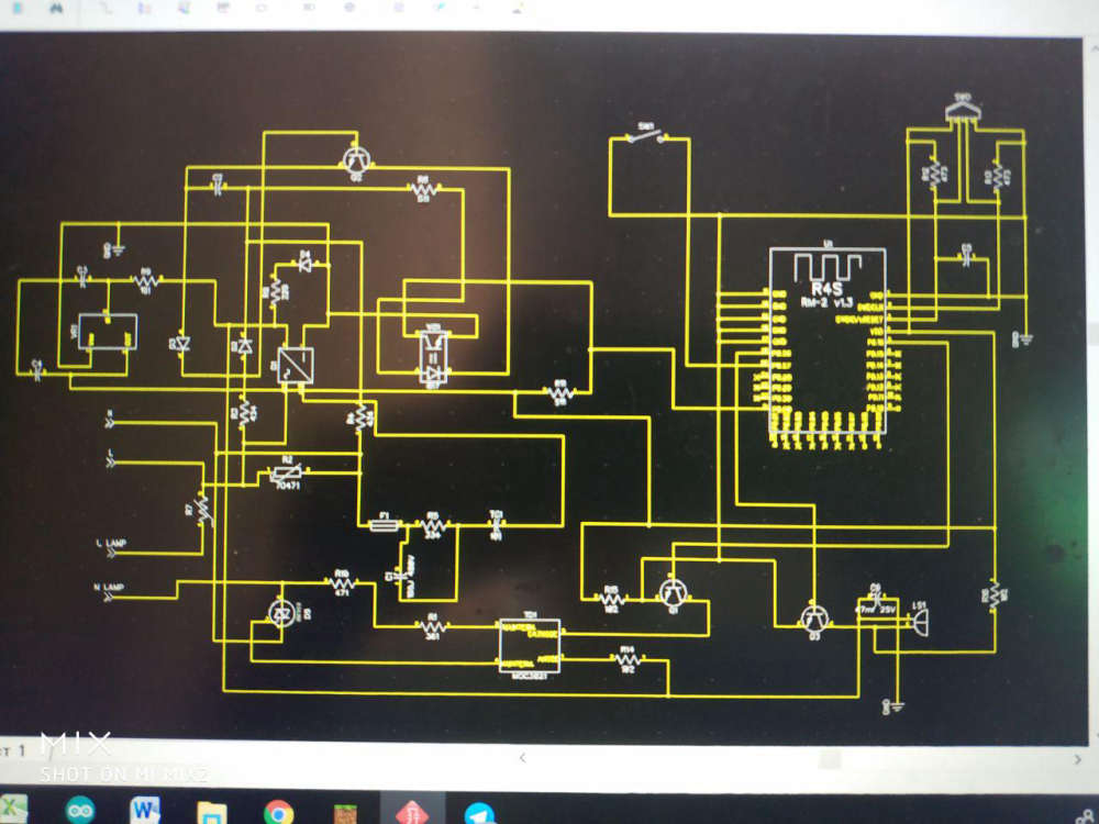
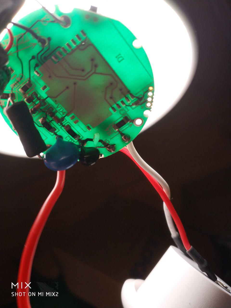
@berkseo very cool! How did you do that? Did you just have to connect the serial holes to an ST_LINK adapter or something similar? Was is difficult to open the device? And, most importantly: is your code available somewhere?
-
-
@berkseo whoa, time for a Kickstarter! They look great! Where did you have them made, and what do they cost?
@fernando-alvarez-buylla Always nice to see the Aurora theme being used :-)
-
@berkseo very cool! How did you do that? Did you just have to connect the serial holes to an ST_LINK adapter or something similar? Was is difficult to open the device? And, most importantly: is your code available somewhere?