What did you build today (Pictures) ?

-
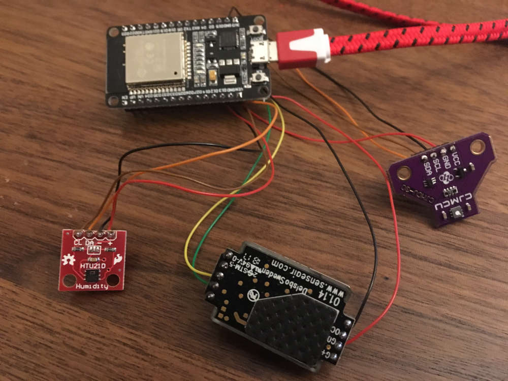
Added two other (e)co2 sensors to my test-setup.
Now 3 NDIR and 2 VOC under observation. :)
-
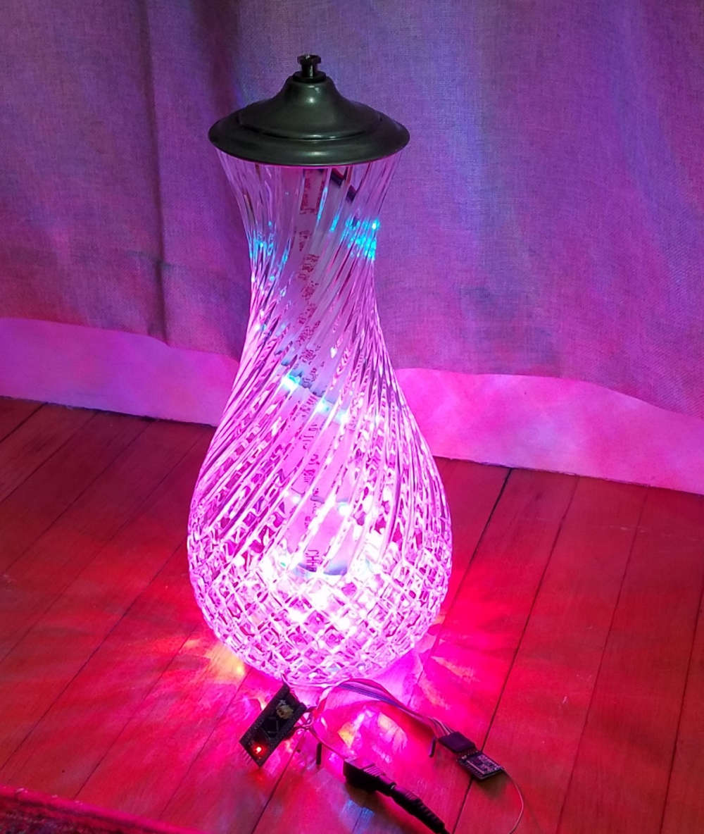
A family member gave me an old lamp with a fancy glass base. Well, I didn't like the lamp, but the base was nice, so I kept it in my basement for a few years. I found it again the other day and decided it needed to become a new type of lamp. I put a 150 LED strip (WS2812B) inside. I have an STM32 Blue Bill and RFM69HCW to run the light patterns and connect to MySensors.
In Domoticz, I have it set up as a dimmer light, but the node just switches patterns depending on what the dimmer level is.
At first, I wrapped the LED strip carefully around a tube that sits in the center of the glass jar, but it didn't look very good. Somehow just spiraling the strip in the bottom of the lamp has a much better effect.
My wife even liked it, so maybe I will put some finishing touches on it and actually use it as a lamp : )
-
@alowhum Soon I will publish codes and the description of process of dismantling and a firmware. But getting ahead.. it's very simple :)
@berkseo
https://translate.google.ru/translate?hl=&sl=ru&tl=en&u=https%3A%2F%2Fmysku.ru%2Fblog%2Fdiy%2F72557.htmlOriginal (code without Google formatting): https://mysku.ru/blog/diy/72557.html
-
Test nRF52840 with Mysensors on Arduino IDE
https://youtu.be/dLXDBjsmVhEbased on source - https://translate.google.ru/translate?sl=ru&tl=en&u=https%3A%2F%2Fmysensors-rus.github.io%2Fnrf52840-The-first-steps%2F
-
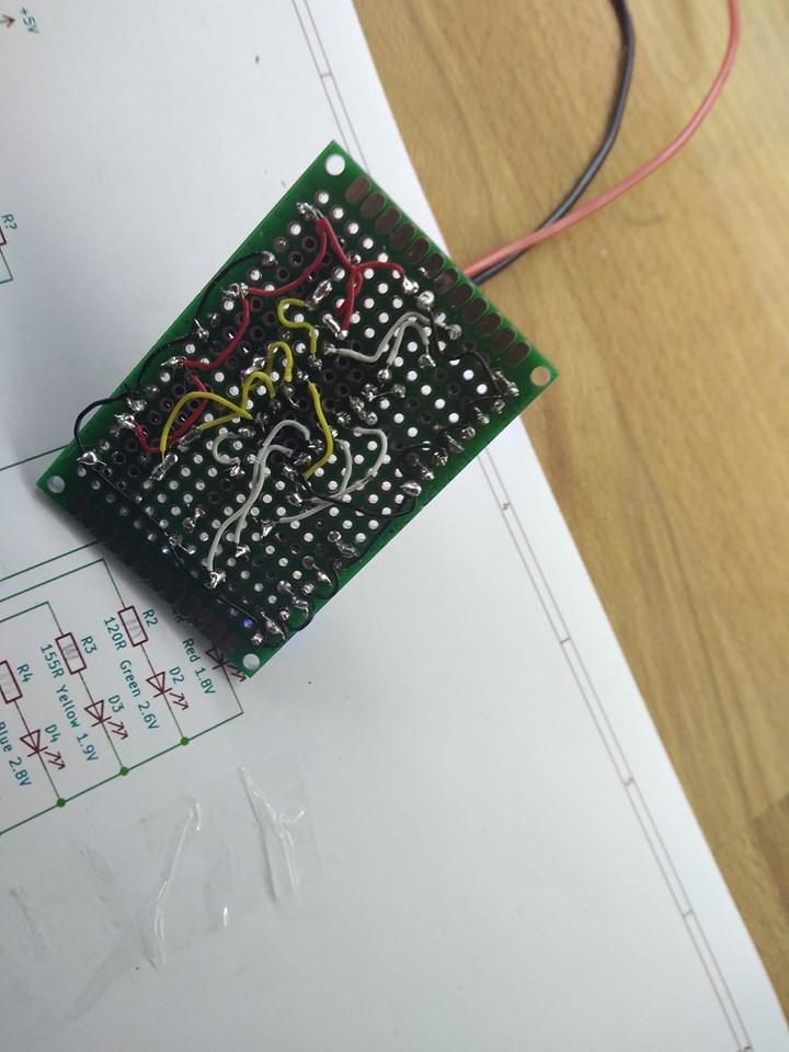
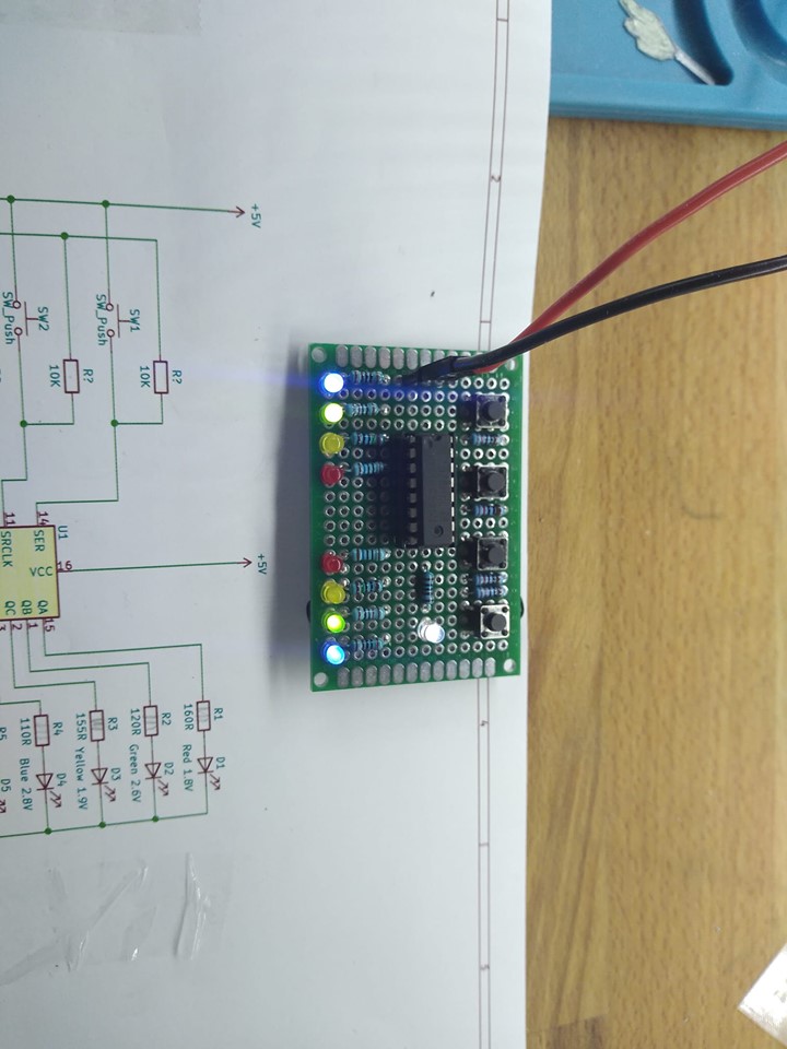
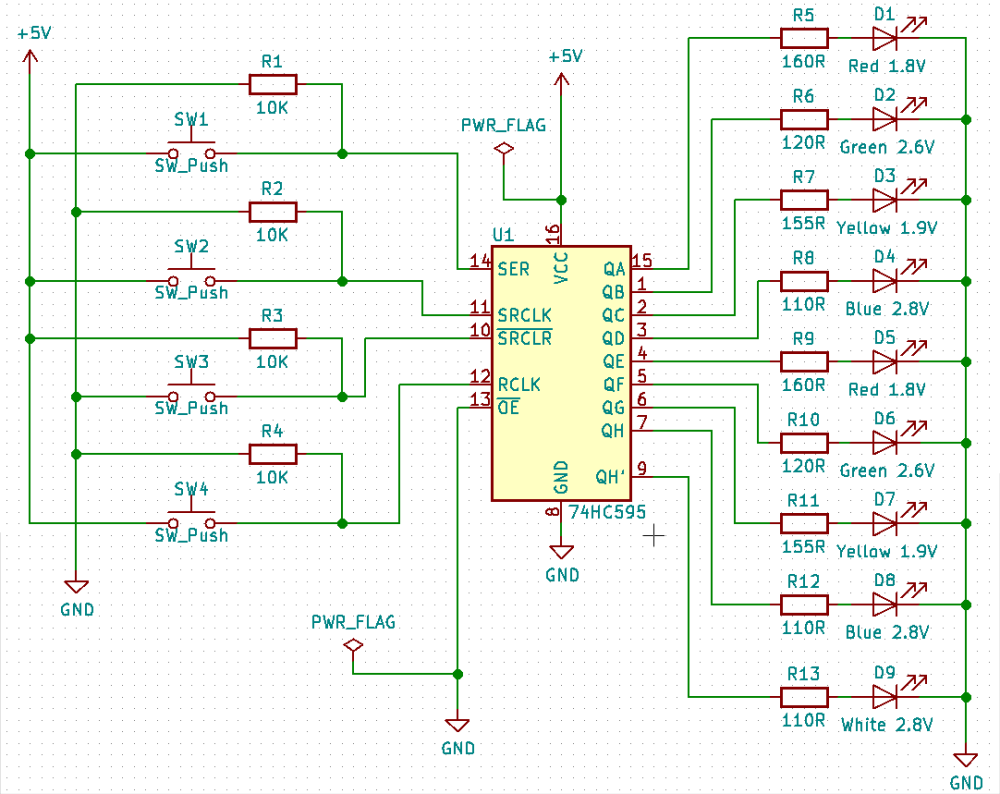
Well, Design of an home made electronic kit for my 10yo daughter to teach her by example. on 74HC595 (shift reg), 9 leds, 4 push buttons, some wrapping wire, ... We managed to build it, it works, with some bad contacts, but it works, she enjoyed the thing and the time spent together. Here is the schema and the pictures. I strongly invite parents to build it with their children, easy and fun. !
-
Well, Design of an home made electronic kit for my 10yo daughter to teach her by example. on 74HC595 (shift reg), 9 leds, 4 push buttons, some wrapping wire, ... We managed to build it, it works, with some bad contacts, but it works, she enjoyed the thing and the time spent together. Here is the schema and the pictures. I strongly invite parents to build it with their children, easy and fun. !
@fanfan
Looks nice, and I love the idea that you spend time and knowledge to your kids :-)
but looking at the current budget it seems that you are above the rated current consumption for the 74HC595, just so you don't wonder in case it burns when several LEDs are ON at the same timeInput clamp current, I IK (V I < 0 or V I > V CC ) ±20 mA
Output clamp current, I OK (V O < 0 or V O > V CC ) ±20 mA
Continuous output current, I O (V O = 0 to V CC ) ±35 mA
Continuous current through V CC or GND ±70 mAData from here:
https://www.sparkfun.com/datasheets/IC/SN74HC595.pdf -
@alowhum Soon I will publish codes and the description of process of dismantling and a firmware. But getting ahead.. it's very simple :)
-
@sincze I should have known. All you had to say was memory and it would have made sense, or should I say sincze. LOL. With needing to hold states of 900 LEDs, I am going to guess that they are WS2812 LED strips.
@dbemowsk I've been gambling with an Adafruit AudioFX board and cobbled together this annunciator. Eventually it will likely be a MySensors node to play alarms or different sounds. It is using a reasonably-priced transportable speaker to play the sounds. I were given it to work with my doorbell button node today.
-
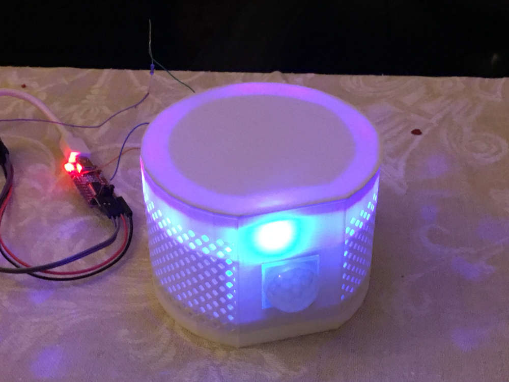
Prototyping my netatmo replacement device. It has an led strip that can simulate a lighouse, a rainbow or a fireplace...
(If not used only for fun, it should warn you, if there is too much CO2 in the air.)
-
Today I have spent a few hours trying to eradicate the confusion between MySensors' different message acknowledgements. See https://github.com/mysensors/MySensors/issues/1103 and https://forum.mysensors.org/post/34263 for details.
 core/MyGatewayTransport.cpp                |  11 ++++++-----
 core/MyMessage.cpp                         |   8 +++++++-
 core/MyMessage.h                           |  31 ++++++++++++++++++------------
 core/MyOTALogging.cpp                      |   2 +-
 core/MyProtocol.cpp                        |  16 ++++++++--------
 core/MySensorsCore.cpp                     |  41 ++++++++++++++++++++-------------------
 core/MySensorsCore.h                       | 114 ++++++++++++++++++++++++++++++++++++++++++++++++++++++++++++++++++-------------------------------------------
 core/MySigning.cpp                         |   4 ++--
 core/MySigning.h                           |   2 +-
 core/MyTransport.cpp                       |  20 +++++++++----------
 core/MyTransport.h                         |   4 ++--
 examples/SecureActuator/SecureActuator.ino |   2 +-
 12 files changed, 147 insertions(+), 108 deletions(-)
I have also updated https://www.mysensors.org/download/sensor_api_20 to use echo instead of ack when describing the echo function. That page didn't have information on the return value for send, present, reqestTime, etc so I added info on the return value as well.
-
When doing the change above, i noticed that after I created https://github.com/mysensors/MySensors/issues/1107 the number of undocumented MySensors keywords has more than doubled!
The plan was to let the MySensors butler check for missing keywords as soon as the few remaining keywords were documented. If I add the check on the existing code, the butler wouldn't allow any commits which would hinder development. But since no-one has documented the missing keywords in over a year, I decided to blacklist the missing keywords and add the check anyway. The new check will give developers a list of new missing keywords, if they add any, so they can be documented.
-
I've also submitted documentation updates for clarifying MY_RX_MESSAGE_BUFFER_FEATURE limitiation on esp8266 and renaming RadioSetting to TransportSetting for https://www.mysensors.org/apidocs/group__RadioSettingGrpPub.html
References:
https://github.com/mysensors/MySensors/pull/1296
https://github.com/mysensors/MySensors/pull/1295 -
-
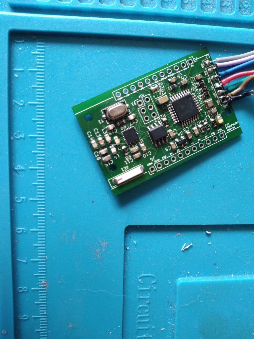
My 3V Node (Atmega328P 1MHz), embedded NRF24L01+ with ceramic antenna, ATSHA256, AT25DF512, BME208, LED, Battery monitoring, ICSP, FTDI, Castelizable, Breadboardable.
-
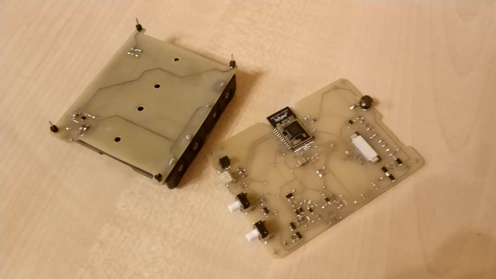
Today finished with the HW part of the new device
-
Great idea @sundberg84
This prompted me to finally get started on something that I've put off for far too long, especially considering how little work it was.I'm still using dupont wires to connect my radios, despite better solutions such as the easypcb being available. But this quick little trick makes it easier to switch the radio modules.
https://youtu.be/Jeg0kS9AcgYYou'll need:
- Dupont female-female wires (I use 10cm), https://www.aliexpress.com/item/Free-Shipping-1lot-40pcs-lot-10cm-2-54mm-1pin-femal-to-femal-jumper-wire-Dupont-cable/32329983091.html
- 4x2 jumper wire connector/header from a 620 pcs kit, https://www.aliexpress.com/item/620-Pcs-1-Set-Jumper-Wire-Cable-Pin-Header-Connector-Kit-Male-Crimp-Female-Pin-Terminal/32816829548.html
- NRF24L01+ radio module, https://www.aliexpress.com/item/Free-shiping-best-prices-10pcs-lot-NRF24L01-NRF24L01-Wireless-Module-2-4G-Wireless-Communication-Module/674686536.html
- Small screwdriver
In the future, I plan to build the other end of the connector for Pro Mini and Rasbperry Pi.
@mfalkvidd
Looks impressive! -
-
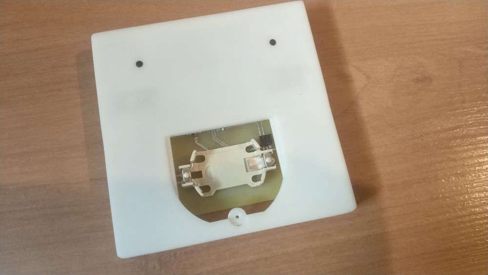
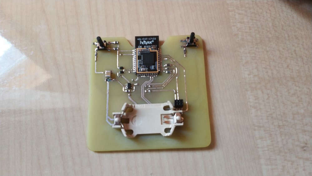
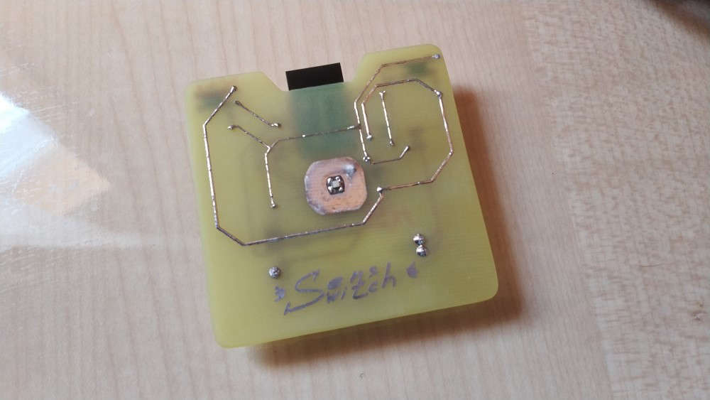
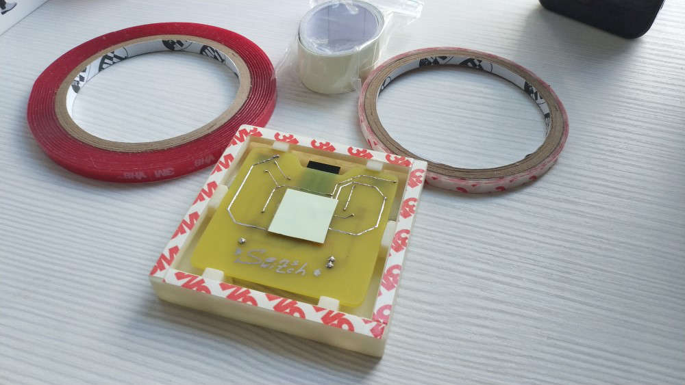
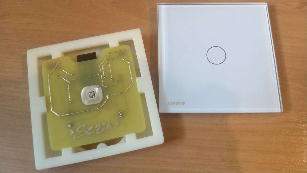
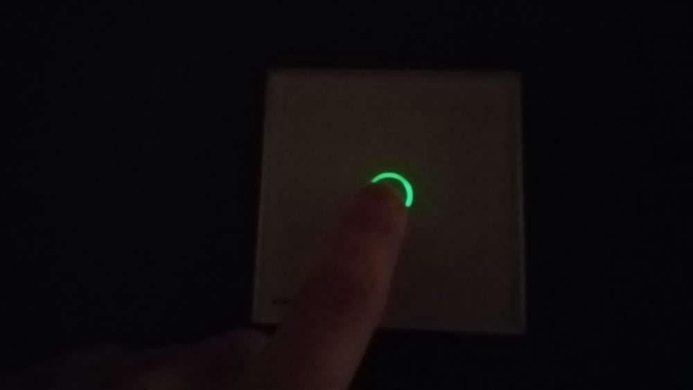
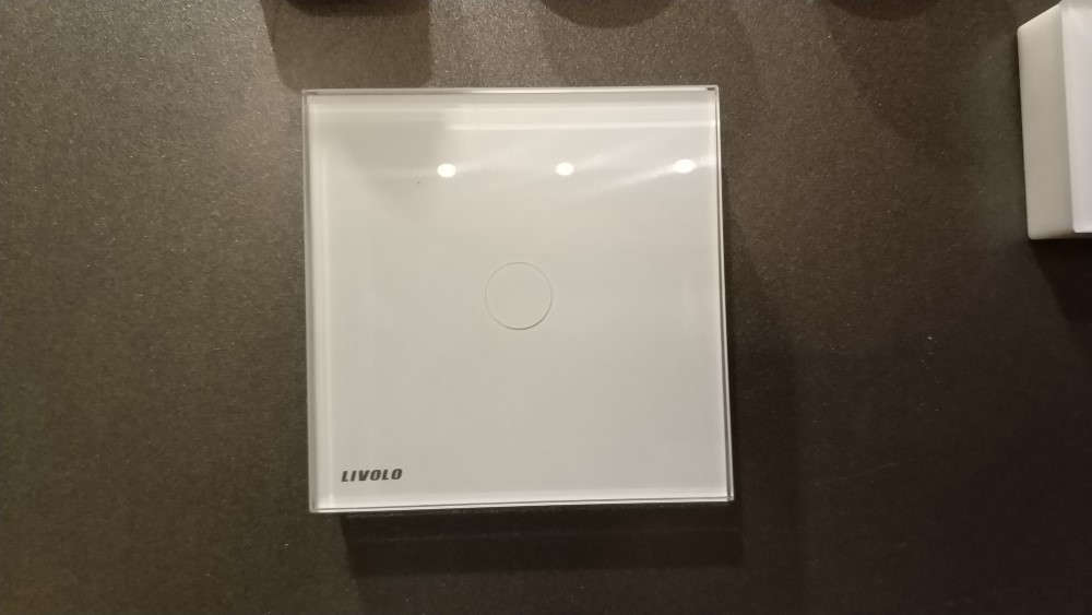
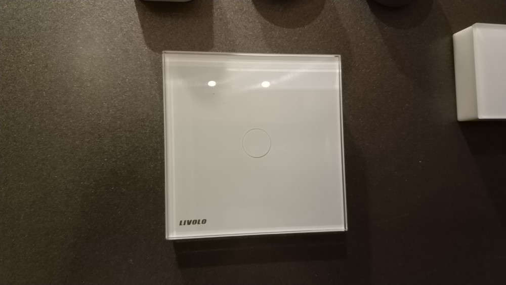
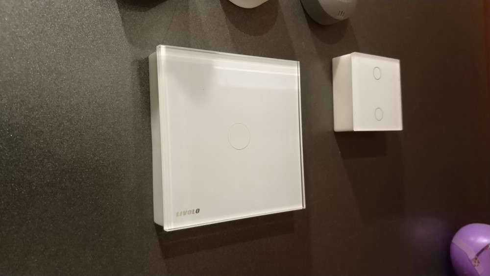
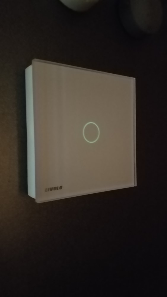
Today.... This MQ2 gas sensor with Neopixel RGB lamp on top and a capacitive touch button under the circle mark on the front.
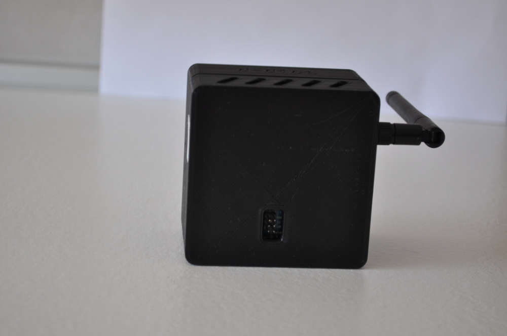
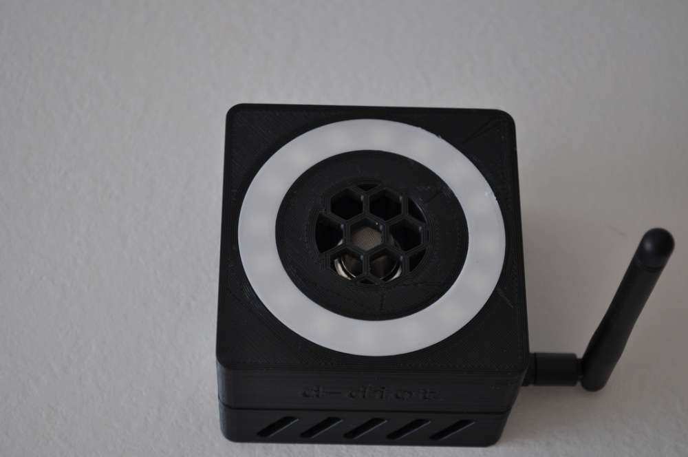
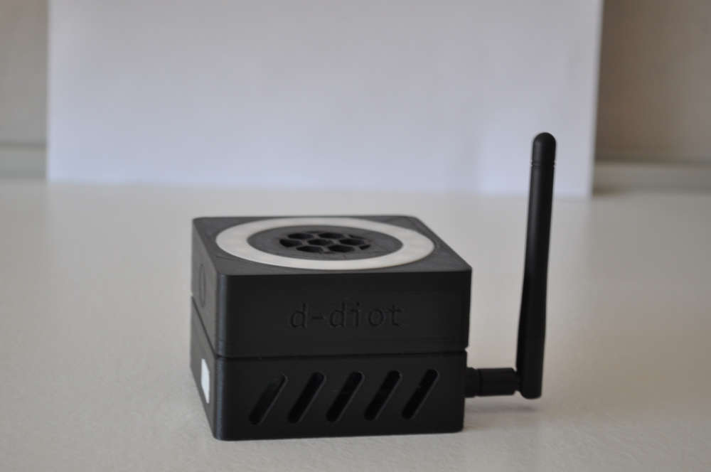
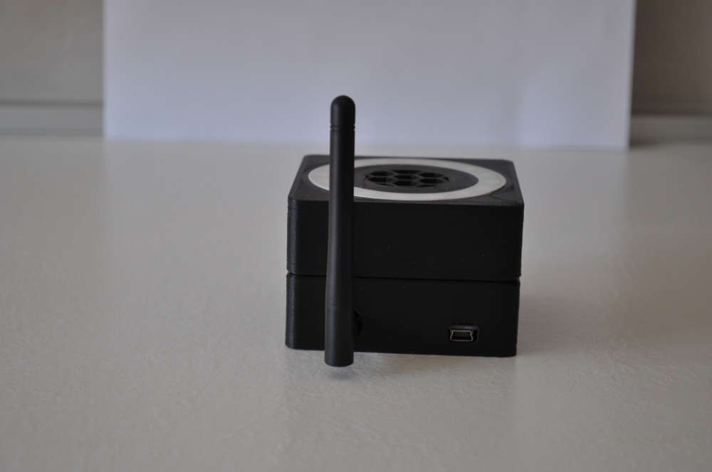
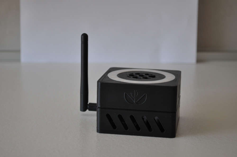
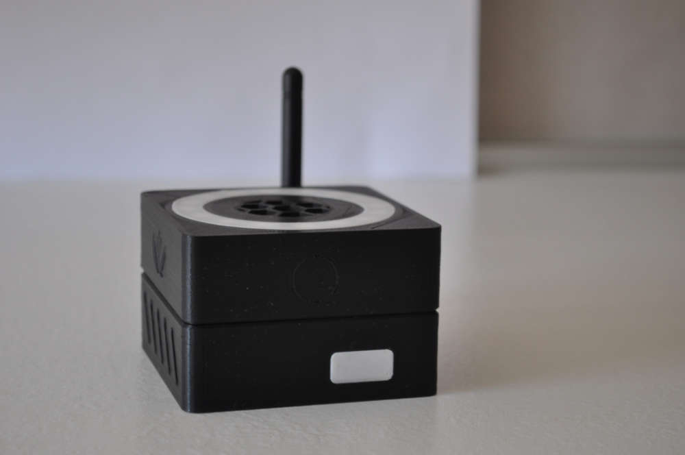
It is part of the d-diot project. The files of the 3d-printable case are available in Thingiverse.
The firmware is available here, the wiki page is under construction.
In the next weeks I will try to print it in wood... Just to increase the WAF :wink: