Solar Powered Mini-Weather Station
-
Please add an wiring diagram. Especially for the solar panel, battery and connection to the Nano.
If i'm not mistaken, the solor panel is directly connected to the power input of the solar charger. @Salmoides wired a mini/microUSB to the power cables to make it easy connect/disconnect. It's this one, from what I can see in the pictures. http://www.aliexpress.com/item/5PCS-Micro-USB-5V-1A-18650-Lithium-Battery-Charger-Board-With-Protection-Module/1852341893.html
From there, it's pretty straight forward. The battery is connected to the B+ and B- leads. The OUT+ and OUT- would be connected to the VIN/RAW and GND on your Nano, respectively.
-
This One looks similar -> http://www.banggood.com/Solar-LED-Motion-Sensor-Waterproof-Wall-Light-For-Home-Garden-Outdoor-p-921885.html
Maybe banggood ships to NL?
-
There seems to be a similar one for sale right now at groupdeal.nl
but just for another 9 hours or so... -
I really liked this project (@Salmoides ThankYou for sharing it)
Expecially the solar powered box.I've successully prototyped one, but would like to report something to pepople trying to also make this.
The solar panel included in the box, is outputting 6V, while the Charger board is sized to acced only 5V as input.
The consequence, is (at least on my prototype) that when there is enought sun, the charger board don't charge the battery (the blue led lights on, and the red seems to vibrate slighty : I guess this is a "protection mode" when VCCin is to high). If i remove the solar panel, and put a usb cable in the charger input, then the RED led lights on, and the barrety is being charged.I guess that slighly modifying the charger board, would allow it to accept 6V as input, but this is too far from my electronic skills (Anyone?)
As a workaround, I've ordered a StepDown module to reduce the 6V provided by the solar panel to 5V for the charger input. I guess It will do the job. I will report back as soon as I get the StepUp module from china.
HTH those interested in this excellent project.
BTW @Salmoides , How did you solved it? Does your Solar panel outputs 5V, instead of 6V? Does your charger works with 6V input (might be slighly diffrent board or mine has an issue)? Did you modified the charger or added extra component to reduce the input voltage ?
Cheeers to evereyone !
-
@Yveaux thank you for the amazing fast and really helpful answer.
Droping the voltage by 0.7v would certainly change the charger beahaviour to behave properly, and not be in "protection mode", Definitively better than inserting a stepDown module.
I assume that I put the diode in serie from the VCC+ out of the Solar panel TO the VCC+ IN of the charger (right?), ie:
Solar VCC out ------ --->| ---- Charger VCC in.3 questions:
- Is there any diode reference recommendation, or any value do the job (1N400x) ?
- Will the diode "eat" some current, ot just drop the voltage -0,7v. ?
- BTW what is a "Silicon" diode?
thank you very much for your valuable support !
Berst regards,
@soif Your connection idea is correct. If you mount it in reverse, it simply won't work.
The actual voltage drop over the diode will depend on the amount of current flowing through it, so that's why you might require 2 in series.An 1N400x will do just fine. The higher the x, the more current it can handle.
The diode will consume some current, but that will be less then a step-down converter.
Most diodes nowadays use silicon as semiconductor. Years ago Germanium diodes were used, which have a lower voltage drop.As a reference: everything you need to know about diodes
http://yveaux.blogspot.nl
-
@soif Your connection idea is correct. If you mount it in reverse, it simply won't work.
The actual voltage drop over the diode will depend on the amount of current flowing through it, so that's why you might require 2 in series.An 1N400x will do just fine. The higher the x, the more current it can handle.
The diode will consume some current, but that will be less then a step-down converter.
Most diodes nowadays use silicon as semiconductor. Years ago Germanium diodes were used, which have a lower voltage drop.As a reference: everything you need to know about diodes
-
The lamp is not shipped to NL and many other countries :unamused: . Did anyone find it in Europe?
@bisschopsr @RiVoW @korttoma Accidentally ran into this one: http://www.aliexpress.com/store/product/1set-Garden-Security-Lamp-16-LED-Solar-Power-Motion-Sensor-Outdoor-Waterproof-Light/124364_32274407358.html
Looks identical, and free shipment to The Netherlands :+1: -
This is similar to the one I have also bought at aliexpress ;-)
-
Hello, thank you for this beautiful project.
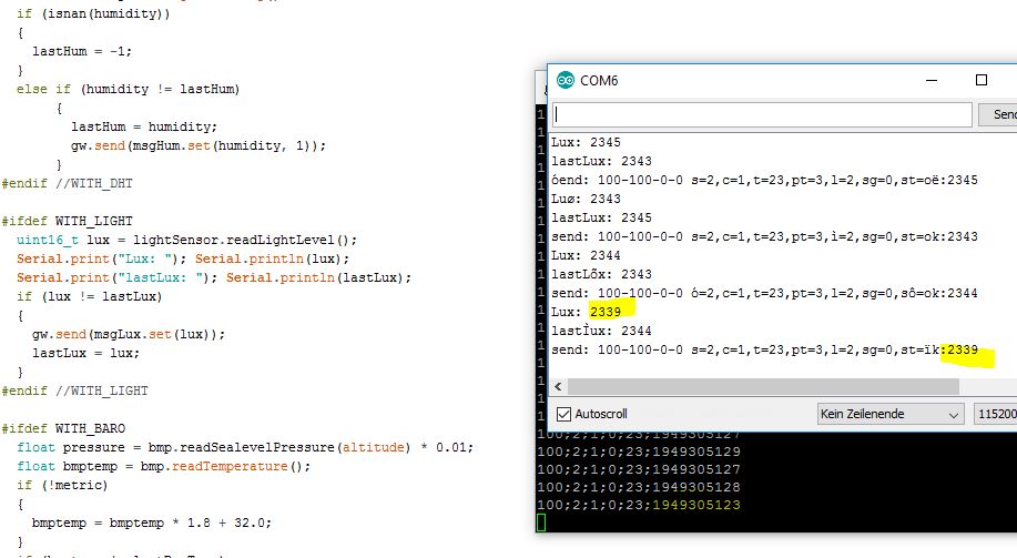
I have recreated it with a DHT22, a BMP180 and a BH1750FVI on a breadboard. From there everything is transferred to Domoticz via WiFi gateway. Everything is working properly. Only the light sensor makes problems ...
The reading of the sensor gives correct values in Lux. These are sent right to the gateway. The Gateway appears to be wrong to interpret these values. It transmits incorrect values via WiFi.
What can I do against it? Did anyone have an idea?
I'm using MySensors 1.5 on Arduino 1.6.7.
Thomas
-
@floris, Thank you for your kind words. The luxmeter faces down, so the light is indirectly collected through the diffuser. If I were to build V2.0, I would look into adding a light pipe to provide more direct lighting on the sensor.
@Salmoides
Hi, where i can find light pipe lie this? -
I have one of these lights and got it with the plan of dissembling it for this very project but it was too good lol so think I'll buy another to dissect. The only disappointing thing is how the light is always on at a dim level so drains the battery. I'd much rather have it only activate on motion detection with the PIR.
-
Dear...
Great project...[ when i got my stuff i am going to build to...Only how do you use the motionsensor of this light...[ new one or do you use the build in one ]
In the sketch is can not see this motionsensor?
Only in our Vera controller is see arm and bypass?
Can you set the level of the lights, in vera?
Two times temperature?
And how is your battery action in the winter-period? -
Hi,
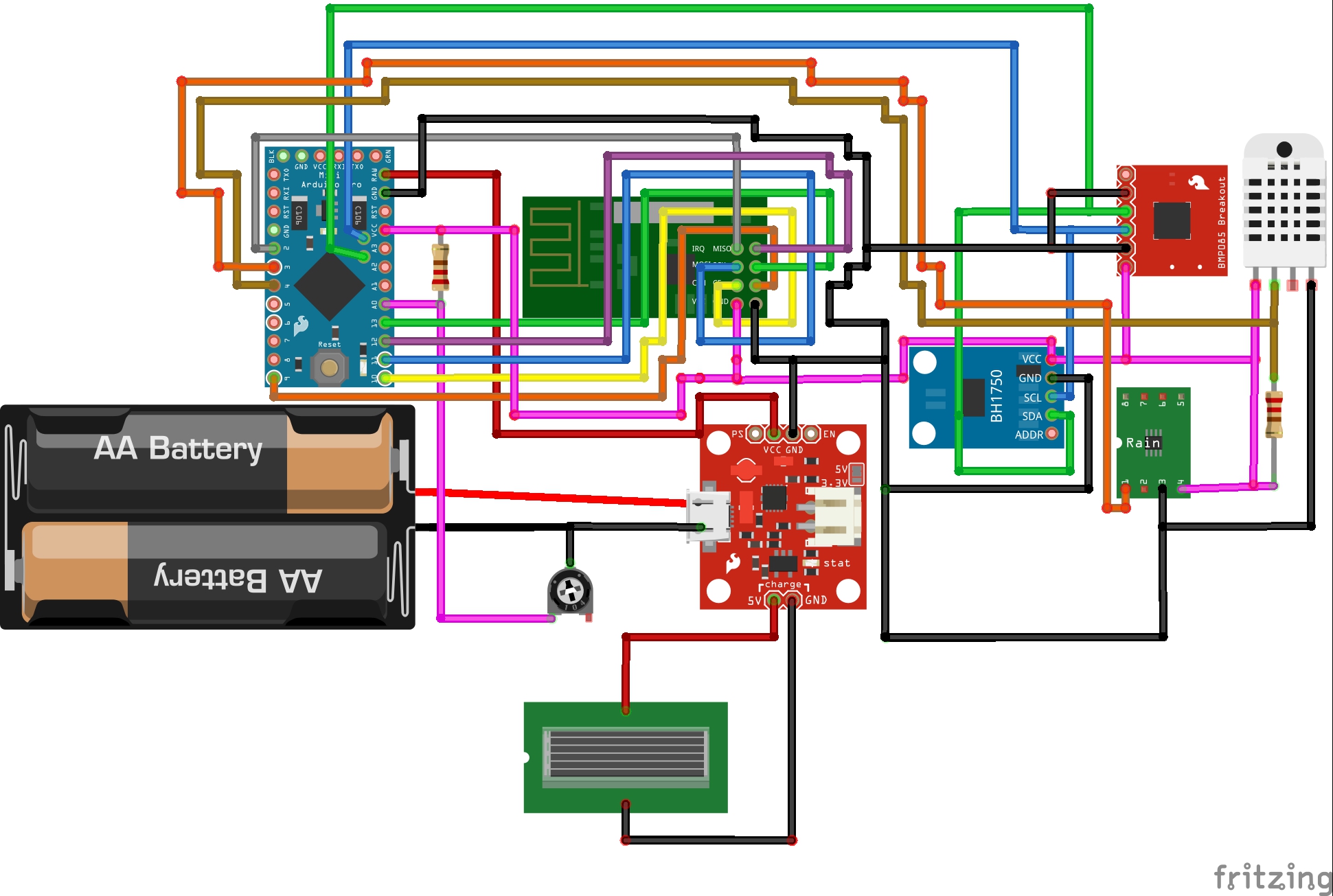
Here is the fritzing shema ; could you please tell me if it is correct before I begin the building of the weather station ?
Thanks for your support !
-
Hi,
The left resistor is a 1Mohm 2W(I'll confirm the power value once I'll received it), the right one is 4,7kohm, 1/4W.
For the Hardware, I read the beginning of the post, but unfortunately I'm also a newby, and need to have a validation of this diagram, because I'm not sure if it is correct, and I don't want to burn my house if I'll do cabling mistakes ;-)
I am not able to put the file created under fritzing, but if someone wants it, tell me how to do it please.Thanks for your feedback!
Regards. -
Hi all,
the lamp used as a basis for this desing is now frequently offered at Aliexpress. Price is around $10,-. DOn't know about quality, but looks very simular.
Ralph