Another possible board - ATMega328, nRF socket, DHT22 socket, MOSFET, Uno pinout
-
@obstler42 Got mine also
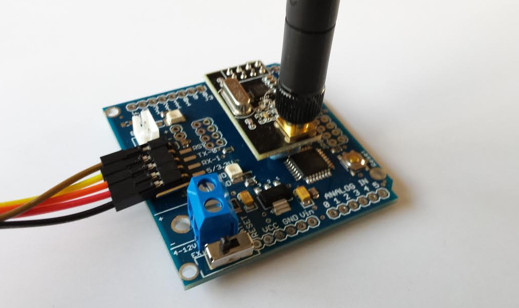
Beautiful boards! I "assembled" all 4 of them and will transform them into Sensors this weekend. At this moment I am powering the boards as shown. Measurement: 4 mA active, < 15uA when in MySensors "Sleep" mode.... nothing removed.. So I don't see any need for replacing/ removing the LDO..
Looks like a very good candidate for future expansion..
-
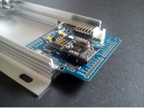
@ServiceXp Not sure yet, probably a cheap ABS box. The enclosure suggested by the seller of this module looks like the perfect fit.. ! with an external antenna.
It can be found on on e-bay (name of the seller in the logo)
-
@ServiceXp Not sure yet, probably a cheap ABS box. The enclosure suggested by the seller of this module looks like the perfect fit.. ! with an external antenna.
It can be found on on e-bay (name of the seller in the logo)
-
@bjornhallberg said:
The xc6210 looks promising though! What's the catch here?
I'm using for a long time xc206, it s one of the best to power NRF24
xc6210 should be also good. Any good proposals on pricing?xc6206 i was purchased $5 per 100pcs
for esp it can be also reasonable to use DC-DC, it will be much more efficient
for example NCP1529 if you need 5V -> 3.3V conversion (1.7A)
or MP2359 if you need to convert any up to 24V (1.2A)
both requires just a few components and a very small SOT23 package
MP2359 costs about $20 per 100pcs and can be used widely
i use them for example to light up and dim strip leds@axillent said:
@bjornhallberg said:
The xc6210 looks promising though! What's the catch here?
I'm using for a long time xc206, it s one of the best to power NRF24
xc6210 should be also good. Any good proposals on pricing?xc6206 i was purchased $5 per 100pcs
Just to add another option...I've been using the Fremont Micro Devices USA FT531JA. It has higher ripple rejection ratio than either of the above and is ~$20 for 100. Not as cheap as the xc6206, but much, much better ripple rejection. So, just another option that I found, it also has the same pin-out as the xc6210!! So, we can try them both with the same PCB design, cool.
-
If interested in another voltage regulator, I can equip a few boards with ADP3338, low dropout and low ground current regulators. Description:
http://www.analog.com/en/power-management/linear-regulators/adp3338/products/product.html
Any other wish - let me know. -
If interested in another voltage regulator, I can equip a few boards with ADP3338, low dropout and low ground current regulators. Description:
http://www.analog.com/en/power-management/linear-regulators/adp3338/products/product.html
Any other wish - let me know. -
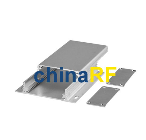
This is the enclosure from the pictures:
http://www.ebay.com/itm/Aluminum-Project-Box-Enclosure-Case-Electronic-DIY-1111-4-33-2-44-0-98-L-W-H-/300376371464?pt=UK_BOI_Electrical_Components_Supplies_ET&hash=item45efd3b108
It's a tight fit. Needs a few strokes with the sand paper over the PCB. No need for drilling holes, though.
And here is one more option for a voltage regulator:
http://www.microchip.com/wwwproducts/Devices.aspx?product=TC2117 -
@obstler42 Got mine also
Beautiful boards! I "assembled" all 4 of them and will transform them into Sensors this weekend. At this moment I am powering the boards as shown. Measurement: 4 mA active, < 15uA when in MySensors "Sleep" mode.... nothing removed.. So I don't see any need for replacing/ removing the LDO..
Looks like a very good candidate for future expansion..
@AWI said:
@obstler42 Got mine also
Beautiful boards! I "assembled" all 4 of them and will transform them into Sensors this weekend. At this moment I am powering the boards as shown. Measurement: 4 mA active, < 15uA when in MySensors "Sleep" mode.... nothing removed.. So I don't see any need for replacing/ removing the LDO..
How are you measuring power consumption? Are you powering from ftdi and measuring on the vcc cable? I've found that when TX/RX are connected and power consumption goes down that with some ftdi boards power is supplied through ftdi TX to the board RX, which makes exact measurements difficult. I only ever connect GND and VIN when measuring now.
So I'd be really interested in how you can get 15 uA sleep with the stock regulator as I spent a whole day trying everything before desoldering it ;)
-
@AWI said:
@obstler42 Got mine also
Beautiful boards! I "assembled" all 4 of them and will transform them into Sensors this weekend. At this moment I am powering the boards as shown. Measurement: 4 mA active, < 15uA when in MySensors "Sleep" mode.... nothing removed.. So I don't see any need for replacing/ removing the LDO..
How are you measuring power consumption? Are you powering from ftdi and measuring on the vcc cable? I've found that when TX/RX are connected and power consumption goes down that with some ftdi boards power is supplied through ftdi TX to the board RX, which makes exact measurements difficult. I only ever connect GND and VIN when measuring now.
So I'd be really interested in how you can get 15 uA sleep with the stock regulator as I spent a whole day trying everything before desoldering it ;)
@obstler42 Oops... . Just tried again and found out that my uA meter was on "autorange". Only a factor 1000 off... I'm sorry for that, how can I compensate. for this stupid mistake..
-
I've made so many mistakes myself trying to optimize for lowest power consumption battery deplyment...
BTW: another gotcha: don't leave the NRF24 on the board when connecting to a 5V FTDI... the FTDI connector voltage pin does NOT go through the voltage regulator but straight to VCC -- which means you'll be roasting the NRF24 with 5 V...
-
If interested in another voltage regulator, I can equip a few boards with ADP3338, low dropout and low ground current regulators. Description:
http://www.analog.com/en/power-management/linear-regulators/adp3338/products/product.html
Any other wish - let me know. -
@ceech Since you are the creator of this board. I am interested in how you use it. Especially how to operate this board on battery power and the power consumption..
@AWI
I normally use a 12V car battery, for monitoring different values in the car. When the board is used in single cell battery applications, I go with a different type of voltage regulator. Normally I use TC2117 3.3V voltage regulator. Unfortunately those regulators are not available for purchase either form Farnell nor Microchip at the moment. They will be available on the 9th of March. So a bit of a set back. As for the enclosure, I use this:
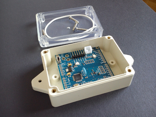
And a little 5V solar cell, when appropriate:
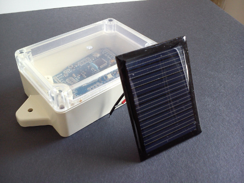
there is also a matter of battery charging, which I leave to this fellow:
http://www.ebay.com/itm/221533778016?_trksid=p2060778.m2749.l2649&ssPageName=STRK%3AMEBIDX%3AIT
I'm also preparing a new board, with integrated battery charger for LiPo, LiIon batteries and some other cool features.
-
@ceech Since you are the creator of this board. I am interested in how you use it. Especially how to operate this board on battery power and the power consumption..
-
@AWI Here is a graphical explanation of the socket connections:
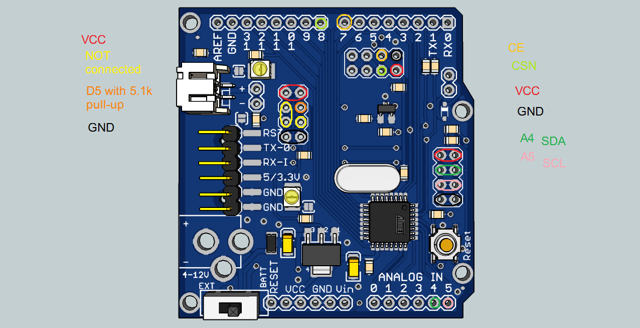
SDA and SCL lines also have pull-up resistors. They are 10k. -
how to upload custom bootloader?maybe you should put additional icsp port
-
how to upload custom bootloader?maybe you should put additional icsp port
@rachmat-aditiya27 The board is kind of hardware oriented, so I ran out of space for the ICSP header. All the needed pins are available though. Either from remaining pins of the NRF24 socket, either from digital 11, 12 and 13 header pins.
-
oh, okay got it :)
-
Hello,
I just got 2 boards and I'em trying to test them. For now I only plugged a usb/serial adapter with an ftdi to the JP3 connector to program the board. The program is simple as Serial.begin(9600); Serial.println("test");But that's not working. The programming was done successfully, and when I open the Serial monitor in the arduino ide, all I got is garbage characters. I have setup the correct communication option in the ide of course. The power VCC comes from my USB and I tried with 3.3v or 5v, but it did not change anything.
When I do the with a standard arduino mini pro, it works correctly, but not with the @ceech boards...
Any idea why and whats wrong here?
thanks -
@Raoul-Hecky said:
9600
may be a baud rate setting error.... else its possible that there is a mismatch of frequency btw the controller HW and the software it is complied for..just a thought