CNC PCB milling
-
@rfm69 said in CNC PCB milling:
PCB pick and place module along with a CNC tool changer in the video above.
Imho, it's certainly a fun project.. but I think you can go faster by hand ;)
Only a thousands more expensive machine will be faster for assembling, and they are more precise, have a lot more features (cam driven features, more feeders etc.).Pick And Place is not plug and play at all :) there is lot of calibration, preparation. So it's useful and save time, only if you plan volume production. This is why there is often fees when you ask for a pcba, they spend time for calibrating each new board, parts in database etc.
There are multiple different diy pnp, most of them are slow, not enough precise for <0402 etc..
If it's for 0603 size with some dfn, low volume, you don't need this kind of investments I think.. but if you want to tinker it's fun I imagine.For example, if I remember well, someone said he can assemble an easypcb in 30mn, trhough hole. Good but that's the time I need to get assembled&soldered one of my compact smd multisensors boards, no PNP, no handsoldering..
PNP is just for placing, it won't fix test, soldering shorts etc, that still need some agility :)No need of a solder paster dispenser, I use stencils. I like freedom for placing parts, but you can also build a simple manual pick&place in case you shake when placing (no shaking here). With a good magnifier, easy! (I have a big one like dentists, + another one with a cam). Finally, the reflow oven cook it. When I need a repair/reflow -> flux + hot air or fine solder tip. Well organized, you're faster like that. Not the same, if you want to assemble 50 boards, agreed.
So, I've no real xp on PNP, but I'm not new at assembling smd boards. Saying this because I already digged in forums, diy builds, reviews, as I need to invest in a cnc router, and PNP this year. and I'm lucky I can talk with local professionals.. I always "try" to get a good ratio between the need/time/ROI . I'll build the cnc router, but I'll buy the PNP. there are a few interesting but it's still a few thousands dollars.
@scalz Agreed... the P&P is beyond my knowledge level, but what I found fascinating in what and how he was doing the project to make something himself, how he evolved the project was very interesting.
He's got something similar for a tool changer on a 3d printer which is very nicely designed... along with the software and controllers.
-
Looks as though StepCraft makes a tool changer that you can buy:
https://youtu.be/pCMdPF39Uts -
@neverdie I saw this stepcraft automatic tool changer, its nice, but the design aproach of Franks is really novel, and way cheapper, simple ingenious. But my skill level is much lower, so I could be wrong :)
-
@rfm69 Does he describe in detail somewhere how to make one? I mean, I get the concept, but he did a lot of work on both the hardware and the software to make it functional.
@neverdie you mean the tool changer, yes he has a blog and git pages where he shares. Its neccessary to speed control with current limiting breaking the spindle, which he's done via cheap ebay motor controller and arduino. Same goes for the spindle locking mechanism powered by a servo. and the CNC software..
Heres the git link text
Heres the blog link text
Its not step by step, perhaps he'll get their but I know he'll be happy if people copy, or chime in :), or add
-
I noticed that Frank is apparently using carbon fiber tubing on his 3D printer. It turns out that carbon fiber tubing is an easy upgrade, if what you have already is aluminum rod:
https://youtu.be/0Pg-L1pQ6qUHowever, its Young's modulus appears to be about 10% less than steel, which I interpret to mean that it is a bit less rigid than steel (cf https://www.christinedemerchant.com/youngmodulus.html).
For the printer in the video that I linked, I can see how reduced weight may be worth the tradeoff.
However, since weight isn't really much of a factor in the 2418 CNC, I think it makes sense to stick with hardened steel rods.
Am I missing something? Opinions?
-
@neverdie once the assembly is done, you should adjust the stepper drivers' current limiting as well.
it is pololu a4988, you can find the corresponding details here:
https://www.pololu.com/product/1182then, it is always good idea to have the basic settings exported from the board, just in case... you can do it by "$$" command sent from the g code sender gui or directly from the serial terminal.
currently I use the following settings, the machine might be able to create nice results with higher feed rates, but I did not have enough time to test it and I sticked to the current working config.
isolation routing with 2001 bits:
- z cut: -0.05mm
- feed rate: 200
you can calculate the V carving bit's tool width for the given milling depth with the following formula:
tan(bit angle/2) * milling depth * 2 + bit's end width
for excel formula the bit angle should be provided in radians, so it should look like this
tan(radians(bit angle/2)) * milling depth * 2 + bit's end widthedge cut or hole milling with the 0.8mm endmill:
- feed rate: 170
- z cut: -1.7mm
- multi depth, depth/pass: 0.2mm
drilling:
- feed rate: 130
- z cut: -1.8
the spindle should be 1000 everywhere.
most probably your board will not have a bootloader, so it will not be possible to update the firmware via usb serial connection (with avrdude), but it is worth to try it. for me it did not work, so I traced back the MCU pins to the pin rows and used ISP to upgrade the firmware to grbl v1.1f (the board will come with 0.9j if I remember correctly). do not forget to export the gerber settings before you upgrade the firmware, as it will loose those, and you have to re-assign the given values again, after the update.
the ISP pinout (from the pin row's top left corner):
Reset -> pin 2
SCK -> pin 3
MISO -> pin 12
MOSI -> pin 135v -> pin1
gnd-> bottom row(!) e.g. pin 1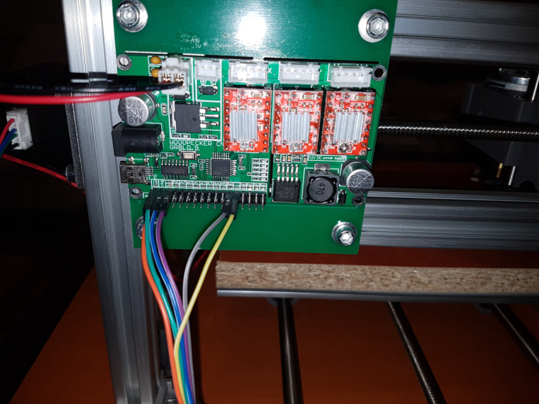
-
I'm noticing that the tips on 0.1mm etching bits last well enough if the PCB substrate if bakelite, but not very long at all if it's FR4. 0.2mm bit tips on FR4 seems to last much better.
-
I noticed that Frank is apparently using carbon fiber tubing on his 3D printer. It turns out that carbon fiber tubing is an easy upgrade, if what you have already is aluminum rod:
https://youtu.be/0Pg-L1pQ6qUHowever, its Young's modulus appears to be about 10% less than steel, which I interpret to mean that it is a bit less rigid than steel (cf https://www.christinedemerchant.com/youngmodulus.html).
For the printer in the video that I linked, I can see how reduced weight may be worth the tradeoff.
However, since weight isn't really much of a factor in the 2418 CNC, I think it makes sense to stick with hardened steel rods.
Am I missing something? Opinions?
@neverdie I'm gathering parts to make the same 3d printer with the carbon rods. I understood the weight reduction on the moving parts with carbon rods was the reason to go for them. And with the light 3d printer head that model can print much faster because of the stability and lightness. Which perhaps dosn't apply for the 2418 cnc ?
-
I noticed that Frank is apparently using carbon fiber tubing on his 3D printer. It turns out that carbon fiber tubing is an easy upgrade, if what you have already is aluminum rod:
https://youtu.be/0Pg-L1pQ6qUHowever, its Young's modulus appears to be about 10% less than steel, which I interpret to mean that it is a bit less rigid than steel (cf https://www.christinedemerchant.com/youngmodulus.html).
For the printer in the video that I linked, I can see how reduced weight may be worth the tradeoff.
However, since weight isn't really much of a factor in the 2418 CNC, I think it makes sense to stick with hardened steel rods.
Am I missing something? Opinions?
@neverdie Wall thickness as well as the material characteristics determine tube stiffness, comparison on the modulus alone is misleading.
As well as carrying the load, the section must also support it's own weight, one aspect where carbon fibre will out-perform steel. -
What's the best way to check the RPM on my spindle? From looking at similar spindles on-line, I think it might be as low as 6000RPM at 24v.
So.... if I upgraded to a spindle that could go, say, 12000RPM, could I simply increase my feedrate by 2x and be done twice as fast? -
@neverdie Wall thickness as well as the material characteristics determine tube stiffness, comparison on the modulus alone is misleading.
As well as carrying the load, the section must also support it's own weight, one aspect where carbon fibre will out-perform steel.@zboblamont said in CNC PCB milling:
@neverdie Wall thickness as well as the material characteristics determine tube stiffness, comparison on the modulus alone is misleading.
Granted. What's a better way to compare them based on the available info?
-
@zboblamont said in CNC PCB milling:
@neverdie Wall thickness as well as the material characteristics determine tube stiffness, comparison on the modulus alone is misleading.
Granted. What's a better way to compare them based on the available info?
@neverdie Bluntly no idea whatsoever, I was merely highlighting the incorrect interpretation.
There is no magic bullet, that's why engineers are still in business, the analysis can be complex.
Were I looking at such a project it would to the lightest and stiffest complex alloy extrusions I would be focusing attention, and figuring out how best to combine them in a frame with minimal deformation.
Complex alloy extrusions are cheap sections with known quantified parameters and constraints, composites are relatively new, and their interconnections are less well understood than with conventional materials. unless you work for Lotus or Ferrari... -
@NeverDie -- the motors used in 1610 CNC mills are generally what are called a "775 Motor". You might be able to find other specs, but the ones I've found suggest that at 24V and no load , they claim 7kRPM -- http://linksprite.com/wiki/index.php5?title=File:Motor_performance_parameter.png; I'm not sure how much slower we could expect it to be while milling. As far as actually measuring this, there are devices you could buy, but you could pretty easily fabricobble your way to an answer if you wanted to make a project out of it: http://www.instructables.com/id/Measure-RPM-DIY-Portable-Digital-Tachometer/.
I have the same mill as you, and swapped for one of these https://www.amazon.com/gp/product/B074FVKRZM/ and have had much better results so far.
-
@NeverDie -- the motors used in 1610 CNC mills are generally what are called a "775 Motor". You might be able to find other specs, but the ones I've found suggest that at 24V and no load , they claim 7kRPM -- http://linksprite.com/wiki/index.php5?title=File:Motor_performance_parameter.png; I'm not sure how much slower we could expect it to be while milling. As far as actually measuring this, there are devices you could buy, but you could pretty easily fabricobble your way to an answer if you wanted to make a project out of it: http://www.instructables.com/id/Measure-RPM-DIY-Portable-Digital-Tachometer/.
I have the same mill as you, and swapped for one of these https://www.amazon.com/gp/product/B074FVKRZM/ and have had much better results so far.
@adam-coddington said in CNC PCB milling:
and have had much better results so far.
Any less vibration also?
-
I actually haven't had much trouble with vibration, so I can't really speak to that. The problems I've had have mostly been around runout, occasional arcing in the old spindle causing enough EMI to reset the microcontroller, Z-Axis backlash, the super-slow milling speeds necessary when spinning at such a low RPM, copper flakes everywhere, etc. Having the faster (and, maybe unfortunately, heavier) brushless spindle has been great for all of those things.
I happened to notice you looking into tool changers; if you're using bCNC, you might not have noticed the tool change workflow -- it's actually pretty elegant and will automatically re-zero your Z-Axis. It does require having a limit switch on at least the top of that axis, though. I used to hate tool changes given how tedious they were, but now they're pretty effortless.
-
Seems like most DC CNC spindles can do no more than 12,000RPM (if that). Which leads me to wonder: would replacing a spindle with a dremel be advisable? A dremel has an adjustable range of 5,000 to 35,000RPM.
Anyone tried this? Any downsides?
[Edit: I see that a number of the AC powered spindles can go as high as 24,000RPM. e.g.: https://www.aliexpress.com/item/1-5kw-Air-Cooled-Motor-cnc-Spindle-Motor-Spindle-110v-220v-ER11-CNC-Square-Milling-Machine/32850346694.html?spm=2114.search0104.3.53.6e8c5be0Uqy1Fs&ws_ab_test=searchweb0_0,searchweb201602_5_10152_5711320_10151_10065_10344_10068_10130_10324_10342_10547_10325_10343_10546_10340_10548_10341_10545_10084_10083_10618_10307_5711220_5722420_10313_10059_10534_100031_10103_10627_10626_10624_10623_10622_10621_10620,searchweb201603_25,ppcSwitch_5&algo_expid=42fb944e-06c3-4821-8a8b-3b49200ec2fd-8&algo_pvid=42fb944e-06c3-4821-8a8b-3b49200ec2fd&transAbTest=ae803_3&priceBeautifyAB=0
That sure would be interesting!
-
I suppose another factor worth considering is audible noise. Here's one that claims to be relatively quiet:
https://www.inventables.com/technologies/quiet-cut-spindlehttps://www.youtube.com/watch?v=g259rm2tfbA
It only goes to 12,000RPM, but I may be willing to trade speed for quiet. I can only assume that the 60000RPM unit isn't very quiet. Not at all sure how the brushless motor would compare. Possibly quieter?
-
I upgraded my CNC LoRa remote monitor into a more universal remote control by making it more compact and giving it 14 buttons:
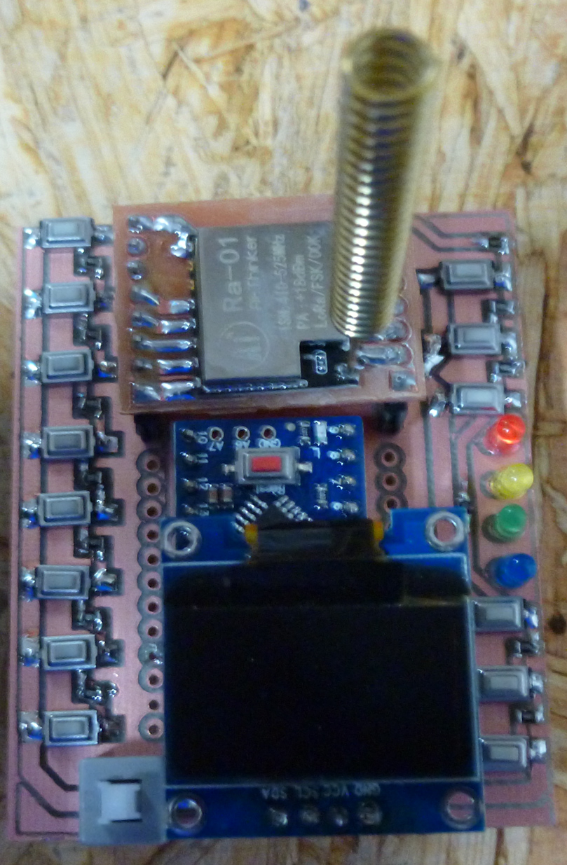
It turns out I can count the number of auto-leveling probes performed, in real time, because the total CNC current briefly drops to almost zero each time the probe makes contact with the PCB. Thus, this gives me a way of tracking auto-leveling progress remotely. :)
-
I went ahead and ordered this spindle upgrade, which looks as though it may be the same (?) as the Quiet Cut spindle.
https://www.aliexpress.com/item/BEST-300W-Mini-Spindle-motor-DC12-48V-ER11-12000rpm-Engraving-milling-grind-air-cooling-spindle-motor/32799767627.html?spm=a2g0s.13010208.99999999.262.sgcb5Q -
I'm also looking for a good spindle so thanks for the links and comments.
Thought I'd share this link text. Its the 30A High Power Single way H-bridge DC Motor Driver Module. That "Frank From Germany" found and is using as part of his tool changing, along with a current sensor so he can brake, reverse and control speed on his tool changer, via arduino, to make it all work.