CNC PCB milling
-
I'll try it both ways. I've already own roughly the same kind of roller as executivul, so I'll try that first. My wife has a laminator that takes 20 minutes to warm up, so I could pass it through that before it gets hot.
I was leaning toward the screed approach, but not sure if would still work well if there's going to be artwork placed on top. Meh, maybe just flatten it in a press. That would do it for sure (well, if the plates are parallel that is).
@NeverDie oh btw, I have not seen air bubbles.
-
I just now stumbled across this, which is actually kinda interesting:
https://www.youtube.com/watch?v=pf7S5KXng6o&list=PLcVGA0RegYfzAcEsDU7aBQKMtvXU8rd19&index=43Basically it shows that with very little time or effort you can create a print screen. If you were to create a print screen for solder mask, you could squeegee the solder mask through the print screen onto the PCB and the solder mask paint would be printed just exactly where you wanted it to be and nowhere else. Then all you would have to do is UV cure it, and you'd be done.
To illustrate, here's a video of what looks like wretchedly impoverished people making PCB's, but it illustrates print screening of solder mask:
https://www.youtube.com/watch?v=zw0H5-OlRs0(Prior to this scene, the same poor souls used the same screen print method to lay down the copper mask. They then etched the copper, which led directly to this scene). The quality seems consistent with a lot of the cheap boards one might come across on aliexpress.
It also opens the door to the possibility of having real "silk screen" printing of artwork onto the final PCB as well. which so far I haven't seen any other discussion regarding how to do.
In terms of cost, it's more expensive than the techniques we've so far been discussing, but the cosumables are less costly than, say, sending off to JLPCB with rapid DHL return shipping, and you obviously get the results far faster than JLPCB would ever be able to deliver them to your doorstep. Plus, for small PCB's it seems likely that you could cut down the fabric to only the amount needed, and thus the material costs could be stretched out over possibly many different design iterations.
-
"Houston, we have closed the loop."
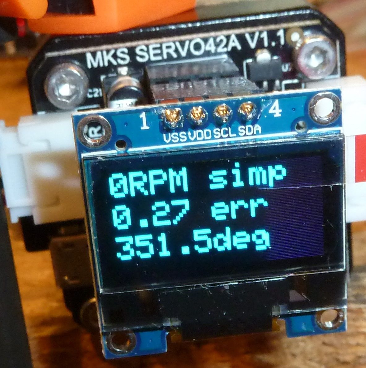
It's up and running. In 256 step mode, it is barely even audible.
However, given that, for a closed loop system the picture seems to represent a anomaly. Can you guess what it is? After jogging the motor around a bit, I stopped and let the stepper idle at what it thinks should be 351.5deg, based on the steps that I sent to it, but which the encoder measures as being 0.27 degree different than that. Well, we know that a full step would be 1.8 degrees, so if it is truly microstepping at 256 ,that means that each microstep should be able to advance the motor by 1.8/256=0.007 degree. Right? So, here's the rub: if the motor is idling, why hasn't it corrected, or at least significantly reduced, the 0.27 degree error? 0.007 degree is much less than 0.27 degree, so it should have adjusted the stepper's true position to be much closer to what its theoretical position should be. Yet, it isn't. Why not?
Well, maybe it can't actually do 256 microsteps. Maybe it can do only 128. That would mean that it should be able to make each microstep be 0.14 degree. Right? But, if that were true, then being closed loop it again should have moved the stepper to bring it closer to what it should be. But it didn't.
So, here's my theory: it's can't actually do 128 microsteps either. Maybe the most it can do is 64 microsteps. In that case, each microstep would be 0.28 degree. Right? But the error is 0.27 degree, which is less than 0.28 degree. Maybe that's where their algorithm gives up and stops. However, if it were me writing the code, I would have made it so that it moves one microstep closer to where it should be, even if that means overshooting by 0.01 degree. That's because being off by 0.01 degree is better than being off by 0.27 degree. But it didn't do that.
However, if we assume that whoever wrote the code actually did the best job that could be done at closing the loop in this scenario, then the obvious conclusion is that this stepper driver can actually do at most 32 microstepping and nothing more. Why? Because in that case each microstep would be 0.56 degree, and so trying to close the loop by moving the stepper one microstep toward the position it ideally should have would mean overshooting by an amount greater than 0.27 degree, and so it's actually better to do nothing in this particular situation.
But if that's the case, why advertise it to have more microstepping than what it's actually capable of?
Anyhow, that's as far as I've gotten with it so far. I guess the next step will be to open up a terminal window to view its output over the usb connection. Perhaps that will shed more light on the mystery.
Edit: Whooops. 1.8 degree divided by 32 is 0.056, not 0.56, so my calculations above are off. Well, I'm heading off to bed right now, so I'll look into that discrepancy tomorrow. Meanwhile, if anyone has thoughts on the 0.27 degree anomaly, feel free to post.
That's it for today. Signing off. :sleeping: :sleeping_accommodation:
-
I just now stumbled across this, which is actually kinda interesting:
https://www.youtube.com/watch?v=pf7S5KXng6o&list=PLcVGA0RegYfzAcEsDU7aBQKMtvXU8rd19&index=43Basically it shows that with very little time or effort you can create a print screen. If you were to create a print screen for solder mask, you could squeegee the solder mask through the print screen onto the PCB and the solder mask paint would be printed just exactly where you wanted it to be and nowhere else. Then all you would have to do is UV cure it, and you'd be done.
To illustrate, here's a video of what looks like wretchedly impoverished people making PCB's, but it illustrates print screening of solder mask:
https://www.youtube.com/watch?v=zw0H5-OlRs0(Prior to this scene, the same poor souls used the same screen print method to lay down the copper mask. They then etched the copper, which led directly to this scene). The quality seems consistent with a lot of the cheap boards one might come across on aliexpress.
It also opens the door to the possibility of having real "silk screen" printing of artwork onto the final PCB as well. which so far I haven't seen any other discussion regarding how to do.
In terms of cost, it's more expensive than the techniques we've so far been discussing, but the cosumables are less costly than, say, sending off to JLPCB with rapid DHL return shipping, and you obviously get the results far faster than JLPCB would ever be able to deliver them to your doorstep. Plus, for small PCB's it seems likely that you could cut down the fabric to only the amount needed, and thus the material costs could be stretched out over possibly many different design iterations.
@NeverDie The UV laminator just gave me the craziest idea: Why don't we take a normal laminator, remove the heating coils and add a strip of UV leds to it??? The expected result: perfect pressing of the artwork to the board and curing at the same time, speed it travels through sets the hardening level. I can get rid of all those glass panels and stuff.
I'm going out hunting for a cheap laminator :) -
@NeverDie The UV laminator just gave me the craziest idea: Why don't we take a normal laminator, remove the heating coils and add a strip of UV leds to it??? The expected result: perfect pressing of the artwork to the board and curing at the same time, speed it travels through sets the hardening level. I can get rid of all those glass panels and stuff.
I'm going out hunting for a cheap laminator :)@executivul good luck.
I noticed that I really have to hold the board and the plastic together, otherwise the rolls will pull the foil off the board.
So that might make aligning the artwork a bit difficult. Perhaps some form of holder for the PCB could prevent the shifting.
-
@NeverDie The UV laminator just gave me the craziest idea: Why don't we take a normal laminator, remove the heating coils and add a strip of UV leds to it??? The expected result: perfect pressing of the artwork to the board and curing at the same time, speed it travels through sets the hardening level. I can get rid of all those glass panels and stuff.
I'm going out hunting for a cheap laminator :)@executivul said in CNC PCB milling:
@NeverDie The UV laminator just gave me the craziest idea: Why don't we take a normal laminator, remove the heating coils and add a strip of UV leds to it??? The expected result: perfect pressing of the artwork to the board and curing at the same time, speed it travels through sets the hardening level. I can get rid of all those glass panels and stuff.
@executivul I like how you think. That's a great idea!
-
@executivul good luck.
I noticed that I really have to hold the board and the plastic together, otherwise the rolls will pull the foil off the board.
So that might make aligning the artwork a bit difficult. Perhaps some form of holder for the PCB could prevent the shifting.
@Joerideman said in CNC PCB milling:
@executivul good luck.
I noticed that I really have to hold the board and the plastic together, otherwise the rolls will pull the foil off the board.
So that might make aligning the artwork a bit difficult. Perhaps some form of holder for the PCB could prevent the shifting.
The margin on the MYOS looks pretty big toward the top and bottom. My guess is it's there, at least in part, for the reason you mentioned.
Also, that cold laminator I posted earlier that you guys pooh-poo'hd had a feature that maybe your particular hot laminator lacks, which is adjustable pressure. You could potentially run it through more than once, and crank up the pressure with each pass. Probably some hot laminators have this type of feature.
-
"Houston, we have closed the loop."
It's up and running. In 256 step mode, it is barely even audible.
However, given that, for a closed loop system the picture seems to represent a anomaly. Can you guess what it is? After jogging the motor around a bit, I stopped and let the stepper idle at what it thinks should be 351.5deg, based on the steps that I sent to it, but which the encoder measures as being 0.27 degree different than that. Well, we know that a full step would be 1.8 degrees, so if it is truly microstepping at 256 ,that means that each microstep should be able to advance the motor by 1.8/256=0.007 degree. Right? So, here's the rub: if the motor is idling, why hasn't it corrected, or at least significantly reduced, the 0.27 degree error? 0.007 degree is much less than 0.27 degree, so it should have adjusted the stepper's true position to be much closer to what its theoretical position should be. Yet, it isn't. Why not?
Well, maybe it can't actually do 256 microsteps. Maybe it can do only 128. That would mean that it should be able to make each microstep be 0.14 degree. Right? But, if that were true, then being closed loop it again should have moved the stepper to bring it closer to what it should be. But it didn't.
So, here's my theory: it's can't actually do 128 microsteps either. Maybe the most it can do is 64 microsteps. In that case, each microstep would be 0.28 degree. Right? But the error is 0.27 degree, which is less than 0.28 degree. Maybe that's where their algorithm gives up and stops. However, if it were me writing the code, I would have made it so that it moves one microstep closer to where it should be, even if that means overshooting by 0.01 degree. That's because being off by 0.01 degree is better than being off by 0.27 degree. But it didn't do that.
However, if we assume that whoever wrote the code actually did the best job that could be done at closing the loop in this scenario, then the obvious conclusion is that this stepper driver can actually do at most 32 microstepping and nothing more. Why? Because in that case each microstep would be 0.56 degree, and so trying to close the loop by moving the stepper one microstep toward the position it ideally should have would mean overshooting by an amount greater than 0.27 degree, and so it's actually better to do nothing in this particular situation.
But if that's the case, why advertise it to have more microstepping than what it's actually capable of?
Anyhow, that's as far as I've gotten with it so far. I guess the next step will be to open up a terminal window to view its output over the usb connection. Perhaps that will shed more light on the mystery.
Edit: Whooops. 1.8 degree divided by 32 is 0.056, not 0.56, so my calculations above are off. Well, I'm heading off to bed right now, so I'll look into that discrepancy tomorrow. Meanwhile, if anyone has thoughts on the 0.27 degree anomaly, feel free to post.
That's it for today. Signing off. :sleeping: :sleeping_accommodation:
@NeverDie said in CNC PCB milling:
Well, maybe it can't actually do 256 microsteps. Maybe it can do only 128. That would mean that it should be able to make each microstep be 0.14 degree. Right?
Wrong. 0.014 degree.
But following the rest of the chain of reasoning with the shifted decimal place, it becomes obvious that something is wrong with the closed loop algorithm, because it proves that not much microstepping granularity is required to correct for a 0.27 degree error.
The shorter way to prove it is simply: 1.8/0.27=6.7. So, even an 8 microstepping division would be able to reduce the final error if the algorithm were to correct the stepper's final position, which it didn't do.
I wouldn't yet rule-out user error though. Not yet sure what that would be, but I'll take another pass at it.
Regardless, I already like it far more than the DRV8825 because it's not blowing up either itself or the GRBL arduino, and it appears to consume a lot less current while jogging.
Because I have only these three controllers to work with, I earlier outfitted all 3 with oversized pure copper heatsinks and permanently secured them tight with artic-silver thermal epoxy:
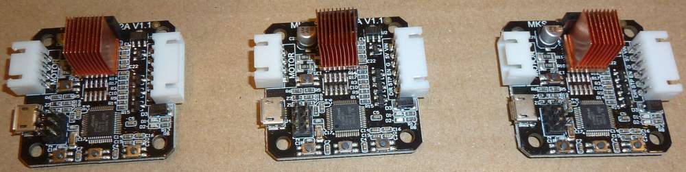
Thinking about that now, I suppose that in doing so there's some risk that, because of the weight, a lot of vibration might eventually rip the entire stepper chip off the board. Meh, hopefully it's moot: I'm etching PCB's, not milling stainless steel. If I were doing that instead, I can see the advantage of not having the stepper driver directly attached to the stepper motor. -
I found this critique of the MKS servo42A by what sounds like my have been one of the developers of the original smart stepper:
http://misfittech.net/blog/makerbase-mks-servo42/He obviously sounds rather bitter about MKS not making their firmware public. However, although I'm not 100% sure, it looks to me as though not long afterward MKS may have posted it to github here: https://github.com/makerbase-mks/MKS-SERVO42A/tree/master/Firmware/stepper_nano_zero
TL;DR: MKS cut some corners when they cloned the servo42A, and so, although similar, in his view it's not as good as the original, which he is still selling for $50 plus add-ons plus shipping. i.e. more than 3x the price of the MKS version. Among other things, he says MKS removed an "error" pin and chose a less accurate magnetic encoder than what his design uses.
-
Ugh. Confirmed: MKS Servo42a uses A1333LLETR-T, which has 12 bit resolution, instead of AS5047D that the mechaduino uses, which has 14 bit resolution. I'm very disappointed.
This compares to uStepper, which uses AEAT8800-Q24, which is a 16 bit magnetic encoder, which according to uStepper gives a resolution of ~0.0055 degrees
For the z-axis I want all the resolution I can get, so I'm going to order a uStepper and see how it compares on the bench. It's 3x the price of the MKS stepper but nominally has 16x the resolution.
-
@NeverDie said in CNC PCB milling:
nominally has 16x the resolution
Why? Going from 12 to 14 bit on the on the encoder will only give 4x the resolution...
@Yveaux said in CNC PCB milling:
@NeverDie said in CNC PCB milling:
nominally has 16x the resolution
Why? Going from 12 to 14 bit on the on the encoder will only give 4x the resolution...
You must have missed it. uSstepper has 16 bit resolution. So, 4 extra bits of resolution.
-
@Yveaux said in CNC PCB milling:
@NeverDie said in CNC PCB milling:
nominally has 16x the resolution
Why? Going from 12 to 14 bit on the on the encoder will only give 4x the resolution...
You must have missed it. uSstepper has 16 bit resolution. So, 4 extra bits of resolution.
-
@NeverDie ah, ok, nevermind. Too many part numbers and bit references in a single post for my peanut brain :grimacing:
@Yveaux said in CNC PCB milling:
@NeverDie ah, ok, nevermind. Too many part numbers and bit references in a single post for my peanut brain :grimacing:
Don't feel bad. Unlike me, you still have your money! I had assumed that because the MKS SERVO42A appeared to be a rip-off of the mechaduino design that they had copied the BOM as well. Instead, they made it worse. If it hadn't found the rant I linked to above, it might have taken me a long-time to realize the difference.
Edit: I just now ordered a uStepper S, which is the 16 bit version. Coming from Denmark with Danish postal shipping (the only option) it may take a couple of weeks to get here. Unless I'm mistaken, it is the highest resolution closed-loop stepper driver+encoder combination currently on the market (well, excluding whatever big ticket industrial solutions may exist). Is it overkill given the other sources of slop in my existing rig? Maybe. I would guess so, but right now I don't have a quantified grasp of just how good or bad the other system components are performing, so I can't really say with any certainty.
Edit: I looked into the possiblity of desoldering the 12-bit encoder on the MKS servo42A and then soldering on the original 14 bit magnetic encoder in it place. Unfortunately, the pinout is different, so that's not a practical option. Looking back, it would have been better to build a mechaduino from scratch using the open source files and thereby completely remove slip-shod aliexpress profiteers from the equation. Lesson learned! It's much harder to rely even on reviews anymore, since many of those now seem to be infiltrated by the marketers. Even on amazon. These days it has become a serious obstacle to making an informed purchase decision.
-
Does anyone here know how to invert (take the negative) of a gerber image? Because it's open source, I'd like to order some extra uStepperS boards (it would be much faster than ordering a fully populated board from Denmark), but they used Altium Designer, which inverts the ground plane:
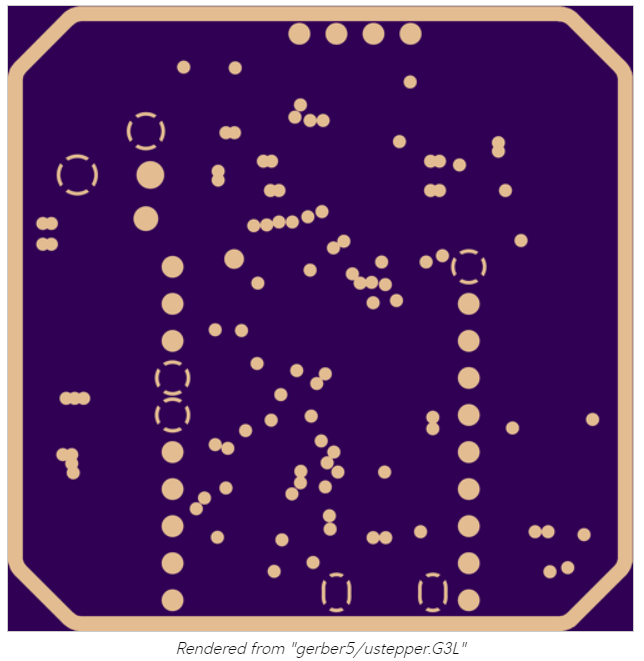
If I were to submit this to a fab, it would come out wrong.In theory, if I were to change the layer to a "signal" layer instead of a "plane" layer, it would be correct. I tried that, but in this case doing that erases the contents of the layer, so that's no good as an after-the-fact solution.
I tried looking for a gerber editor that could do this, but I only found one, and despite it promising "download now", all it did was collect my information and provided no download.
Anyone? Bueller? Anyone?
-
I figure full 14-bit resolution of absolute position will be enough, and that's what the AS5048A promises: https://www.mouser.com/datasheet/2/588/AS5048_DS000298_4-00-1100510.pdf That's 0.0219 of a degree resolution.
As near as I can tell, the AS5047D that the mechaduino chose instead delivered much less than that. According to the datasheet it had " a maximum resolution of 2000 steps / 500 pulses per
revolution." I'm not entirely sure what that means in this context, because in the paragraph just before that it says, "A standard 4-wire SPI serial interface allows a host microcontroller to read 14-bit absolute angle position data
from the AS5047D," which makes it sound as thought 14 bit resolution should have been achievable, but apparently it wasn't. https://www.mouser.com/datasheet/2/588/AS5047D_DS000394_2-00-1513297.pdfIn the case of the AS5048A, however, whatever ambiguity that clouded the AS5047D datasheet has been lifted, because according to https://ams.com/as5048a the AS5048A is capable of 16384 positions per revolution, and it doesn't discuss "steps" at all.
Interestingly, this chip has been on the market for quite a while and so there are a number of github libraries for it. It is protected by a patent filed in 2005 in Europe and 2006 in the US (US Patent 7,095,228).
-
@Renzo-Mischianti Thanks for your post. Looks like you've been quite a busy bee. ;-)
Have you had any success with solder mask?@NeverDie I use this steps, and I'm quite satisfied
https://www.mischianti.org/2019/03/14/design-and-mill-pcb-easy-and-cheap-part-5/
Nothing special, but works correctly..
-
It highly depends on the lead/ball screws, if the tolerances are in range of 0.01mm and backlash at about 0.1mm a 0.X deg of resolution at the steppers/servos doesn't matter since a normal lead screw is 4-8mm/turn.
Even 200 full steps/rev (1.8 deg stepper and full steps) with 4mm/rev screw means 50 full steps/mm or 20 micron/step (0.02mm/step) linear resolution which is much better compared to the rest tolerances of the machine.
On high precision rails, very tightly built machine it might make a difference, but for these cheap routers it doesn't.LE. @NeverDie 0.27 deg error translates to 0.003mm linear error (3 microns) assuming 4mm/rev screws are being used. Do you think you can notice/measure that? (4mm/360)*0.27=0.003 Even if using HUGE 16mm/rev ball screws translates to 0.012mm of error, unnoticeable.
-
Hey @NeverDie, everyone,
It is good to see how this thread developed over the time and you guys are enjoying the PCB milling.
Unfortunately I had many other responsibilities and was super busy, so a lot from my projects had to be postponed. Nevertheless I'm still working with my CNC.A few days ago I replaced the spindle to a laser module to make same plywood engraving, and the original spindle motor holder (the 3D printed stuff) broke during the unscrew...
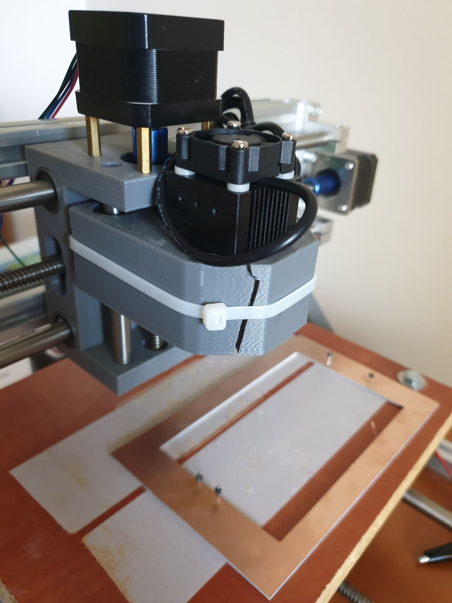
I managed to fix the laser module with cable tie. :)
It is ok for the laser, but of course not for the spindle and for the PCB milling.
Replacement parts are available mostly in packages (e.g. https://www.ebay.com/itm/Replacement-Parts-DIY-Kit-for-CNC-1610-2418-3018-Spindle-Holder-Screw-Polish-Pod/112382449851), but it is possible to print your own version too.
Some guys already came up with an enhanced design, such as https://www.thingiverse.com/thing:3586273I already wanted to make an upgrade on the CNC, so I came to a conclusion, that I will fix the broken part with a custom 3D printed one, then sell the machine.
I already ordered my new toy, a CNC3020T (EUR 325 + shipping EUR 25):
Well, I hesitated a lot and almost bought a CNC3040Z-DQ (bigger, better, ball screw), but as currently I really don't have enough space for it (and to be honest, no reason to buy a better/bigger) I sticked with the 3020T. The quality I achieved with my 2418 will be definitely reproducible and this is enough.
I just read the endmill isolation routing posts. Interesting stuff.
I'm curious whether you can use smaller ones to deal with the 6mil/6mil trace/isolation sizes.Happy milling and cheers!
-
It highly depends on the lead/ball screws, if the tolerances are in range of 0.01mm and backlash at about 0.1mm a 0.X deg of resolution at the steppers/servos doesn't matter since a normal lead screw is 4-8mm/turn.
Even 200 full steps/rev (1.8 deg stepper and full steps) with 4mm/rev screw means 50 full steps/mm or 20 micron/step (0.02mm/step) linear resolution which is much better compared to the rest tolerances of the machine.
On high precision rails, very tightly built machine it might make a difference, but for these cheap routers it doesn't.LE. @NeverDie 0.27 deg error translates to 0.003mm linear error (3 microns) assuming 4mm/rev screws are being used. Do you think you can notice/measure that? (4mm/360)*0.27=0.003 Even if using HUGE 16mm/rev ball screws translates to 0.012mm of error, unnoticeable.
@executivul That's how I previously looked at it, but now I'm looking at it as: total error = sum of individual errors. Previously, for any particular fix I could talk myself out of it by an argument such as the one you articulated. However, even though the individual errors may be small, they may sum up to something bigger that is noticeable. So, this is the first of what I hope will be at least a few refinements, and the hope is that the sum of the refinements will make a difference even if not much is improved by any one of them.
I'm not sure what to do about "following error" though other than to move more slowly. All machines have it to one degree or another. I think everyone who has closed-loop becomes aware of it very quickly because it suddenly becomes so easy to track. I suppose more powerful motors and faster acceleration would help, but ultimately I think maybe better motion planning and control influenced by closed-loop feedback is what's needed. However, I'm not sure if that technology even exists yet. Maybe somewhere in LinuxCNC or something like that? Ultimately, maybe what's needed is closed-loop DRO feedback. The hardware isn't cheap, and figuring out how to retrofit it on to an existing system looks to be challenging. Still, it might be worth it. High quality Industrial grade CNC machines all seem have it.
And what about software backlash compensation? How well does that work? I'm thinking that with DRO monitoring that would be a lot easier to dial in. One thing helps another.