MySensors Hydroponics Greenhouse project
-
So, I’ve been using MySensors all around the house as test devices. I also set up a solar powered Beehive node last autumn, to monitor my hives conditon (went a bit overboard with a total of 6 temp sensors and a humidity sensor.) By the way, the sensors ended up saving my bees.
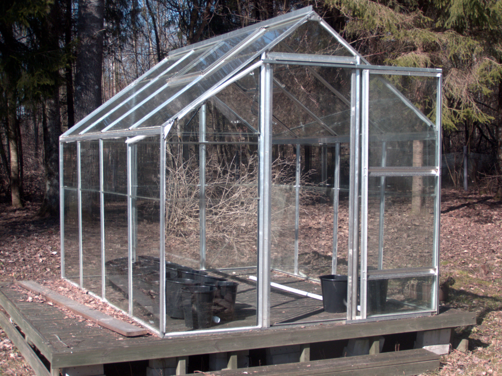
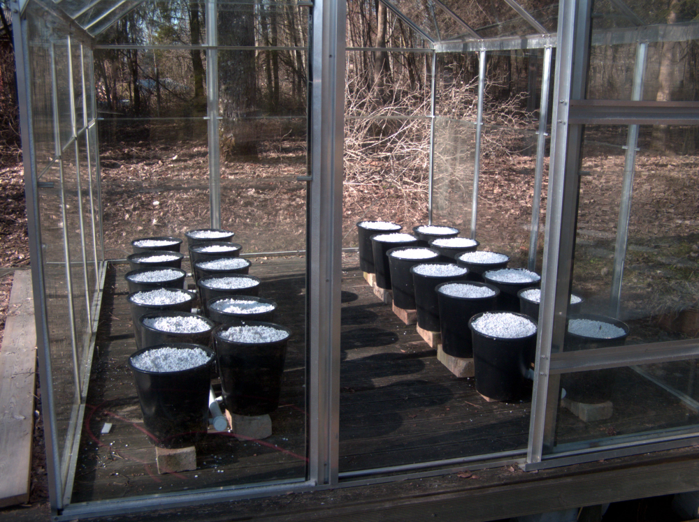
Anyhow, I’m now tackling my biggest project yet. A 6.6m2 greenhouse which I’ll be converting to hydroponics. 44 dutch buckets for tomatos, cucumbers, radishes and a vertical NFT system for herbs.
The goal for now is to monitor the following:
- Nutrient solution pH levels - a kit from Aliexpress
- Nutrient solution EC(parts per million) - a probe from Aliexpress
- Nutrient solution temperature - NTC thermistor 10k
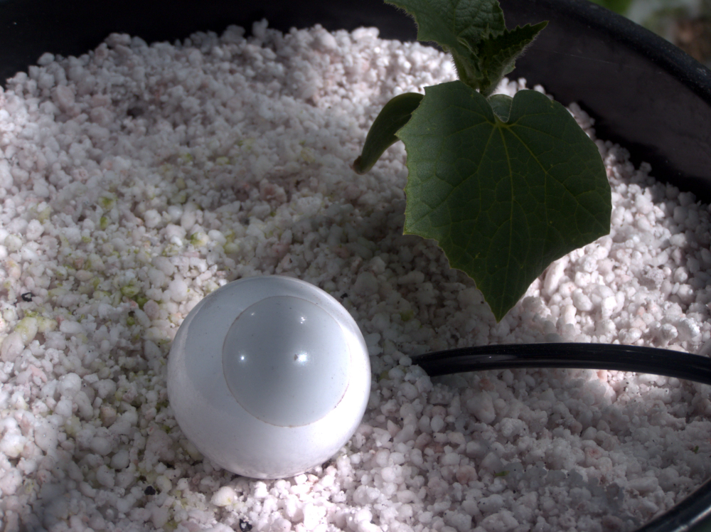
- Nutrient solution level in the tank - ultrasonic transceiver
- Dutch bucket substrate moisture - Moisture pitchfork
- Ambient air temperature - NTC thermistor 10k
- Ambient air relative humidity - SHT21
- Ambient light levels - BH1750
- Some way to monitor if the water is flowing?
As for the actuators, my greenhouse ventilation windows are operated by sylinders with heat expanding gas. So I will have no direct control over them. The only thing I’m thinking that needs operating, are the circulation pumps. I’ll be using a simple dual relay module for that at first with the possibility of switching to a mosfet later on, as it seems the pumps might respond well to a variable input voltage and thus, allow me to fine tune the rate of liquid flow.
The brains for the operation will be Arduino Mega with a sensors shield. I only later realized it's an Uno shield, but luckily the pinouts match and I should be able to use it without much hassle. Might actually be a good thing because I can use a dedicated header for the radio and whatever else I need to connect to the 22+ ports.
-
I look forward to seeing this project progress. Go get it!! :)
-
So, I’ve been using MySensors all around the house as test devices. I also set up a solar powered Beehive node last autumn, to monitor my hives conditon (went a bit overboard with a total of 6 temp sensors and a humidity sensor.) By the way, the sensors ended up saving my bees.
Anyhow, I’m now tackling my biggest project yet. A 6.6m2 greenhouse which I’ll be converting to hydroponics. 44 dutch buckets for tomatos, cucumbers, radishes and a vertical NFT system for herbs.
The goal for now is to monitor the following:
- Nutrient solution pH levels - a kit from Aliexpress
- Nutrient solution EC(parts per million) - a probe from Aliexpress
- Nutrient solution temperature - NTC thermistor 10k
- Nutrient solution level in the tank - ultrasonic transceiver
- Dutch bucket substrate moisture - Moisture pitchfork
- Ambient air temperature - NTC thermistor 10k
- Ambient air relative humidity - SHT21
- Ambient light levels - BH1750
- Some way to monitor if the water is flowing?
As for the actuators, my greenhouse ventilation windows are operated by sylinders with heat expanding gas. So I will have no direct control over them. The only thing I’m thinking that needs operating, are the circulation pumps. I’ll be using a simple dual relay module for that at first with the possibility of switching to a mosfet later on, as it seems the pumps might respond well to a variable input voltage and thus, allow me to fine tune the rate of liquid flow.
The brains for the operation will be Arduino Mega with a sensors shield. I only later realized it's an Uno shield, but luckily the pinouts match and I should be able to use it without much hassle. Might actually be a good thing because I can use a dedicated header for the radio and whatever else I need to connect to the 22+ ports.
-
I just realized there is no MysBootloader for the Arduino Mega 2560. Which means I'm going to try and use the trusty Pro Mini with ATmega328p instead. (I have a version with all analog pins available for use) If I run out of pins or features, I'll switch to the 2560.
So while I'm waiting for the bulk of the sensors to arrive, I'm just creating the general sketch structure.
-
So, a quick update. First of all, I’m considering falling back to the tried and true Dallas temperature sensors instead of the thermistors. At first I figured the thermistors would be an interesting alternative to familiarize myself with but as they require extra components, I’m gonna take the shortcut.
The same goes for the ultrasonic sensor. I’m going to try and find an affordable waterproof distance sensor to use instead.So far I have the relay, light level sensor, soil humidity sensor and the temp sensors hooked up and working. Working on getting the EC sensing part set up. Still waiting for the actual probe, but I should be able to get the firmware done using any random stainless steel rods. It should boil down to calibration in the end.
I currently have 4 digital pins left- hopefully it will be enough.
-
This is where I'm at right now. Support for 2 relays with push buttons, light level and soil moisture measurements. Customizable measurement interval for entire device and each sensor individually. Also a change threshold (a change greater than given threshold in two consecutive readings triggers an immediate report).
Everything is running off interrupts to ensure smooth operation.
NB! I have not yet managed to do live tests with the BH1750 as it has not yet arrived.Next up are the temperature sensors and EC meter. Or whatever sensor will be the next to arrive.
/** * The MySensors Arduino library handles the wireless radio link and protocol * between your home built sensors/actuators and HA controller of choice. * The sensors forms a self healing radio network with optional repeaters. Each * repeater and gateway builds a routing tables in EEPROM which keeps track of the * network topology allowing messages to be routed to nodes. * * Created by Henrik Ekblad <henrik.ekblad@mysensors.org> * Copyright (C) 2013-2015 Sensnology AB * Full contributor list: https://github.com/mysensors/Arduino/graphs/contributors * * Documentation: http://www.mysensors.org * Support Forum: http://forum.mysensors.org * * This program is free software; you can redistribute it and/or * modify it under the terms of the GNU General Public License * version 2 as published by the Free Software Foundation. * ******************************* * * REVISION HISTORY * Version 1.0 - Rait Lotamõis * * DESCRIPTION * First iteration of a Hydroponic greenhouse controller sketch. * Supports: * 2 relays with individual push buttons * BH1750 Light sensor * Moisture sensor * */ // Enable debug prints to serial monitor #define MY_DEBUG // Enable and select radio type attached #define MY_RADIO_NRF24 //#define MY_RADIO_RFM69 // Enable repeater functionality for this node #define MY_REPEATER_FEATURE #include <MySensors.h> #include <Vcc.h> #include <ResponsiveAnalogRead.h> #include <SPI.h> #include <BH1750.h> #include <Wire.h> #include <TimerOne.h> // Measurement and reporting settings #define REPORT_INTERVAL 600 // define report interval in seconds for all sensors. This is when a full report is sent, no matter what #define MOI_MEASUREMENT_INTERVAL 10 // Time in seconds, between consecutive measurements #define MOI_REPORT_THRESHOLD 5 // The difference in % between two consecutive readings to send an immediate report #define LUX_MEASUREMENT_INTERVAL 15 // Time in seconds, between consecutive measurements #define LUX_REPORT_THRESHOLD 100 // The difference in Lux between two consecutive readings to send an immediate report // Relay settings. TODO: Make it easy to use more than two relays #define RLY_PIN_1 4 #define RLY_PIN_2 5 #define RLY_BTN_1 2 // Pin to use for a pushbutton switch. NB! Needs an interrupt pin #define RLY_BTN_2 3 // Pin to use for a pushbutton switch. NB! Needs an interrupt pin #define RLY_ON 0 // GPIO value to write to turn on attached relay #define RLY_OFF 1 // GPIO value to write to turn off attached relay #define RLY_ID_1 1 // MySensors Child ID #define RLY_ID_2 2 // MySensors Child ID // Soil Moisture settings #define MOI_SENSE_PIN A0 // Analog pin connecting to the probe #define MOI_POWER_PIN 6 // Pin for powering the humidity sensor #define MOI_0_PERCENT 0 // Probe output voltage at 0% moisture #define MOI_100_PERCENT 2.5 // Probe output voltage in a glass of water #define MOI_ID 3 // MySensors Child ID // Lux sensor settings #define LUX_ID 0 // MySensors Child ID // General settings #define VCC_VOLTAGE_READ 5.0 // Actual supply voltage going to the VCC. Use a multimeter to check #define VCC_VOLTAGE_REPORTED 4.97 // Set this to the same as above for your first boot. Then insert the value reported in the Serial window during boot #define ONE_SECOND_IN_MICROS 500000 // Depends on your crystal. 8MHz crystal:500000, 16MHz crystal:1000000, etc. If your time intervals are off, this is the reason // Soil Moisture variables float cal0 = MOI_0_PERCENT; float cal100 = MOI_100_PERCENT; ResponsiveAnalogRead analogMoi(MOI_SENSE_PIN, false); MyMessage msgMoi(0,V_LEVEL); float lastMoisture = 0; // Relay variables MyMessage msgRly(0,V_STATUS); bool rlyState1 = false; bool rlyState2 = false; // Lux sensor variables BH1750 luxSensor; MyMessage msgLux(0, V_LIGHT_LEVEL); uint16_t lastLux = 0; // VCC Monitoring for calculations const float VccCorrection = VCC_VOLTAGE_READ/VCC_VOLTAGE_REPORTED; Vcc vcc(VccCorrection); // General variables bool receivedConfig = false; bool metric = true; long reportTimer = REPORT_INTERVAL; long moiTimer = MOI_MEASUREMENT_INTERVAL; long luxTimer = LUX_MEASUREMENT_INTERVAL; const unsigned long debounceTime = 50; void before() { } void setup() { // Initialize the timer interrupt for sending sensor reports Timer1.initialize(ONE_SECOND_IN_MICROS); Timer1.attachInterrupt(countDownOneSecond); // Initialize and set relays to last known states (using eeprom storage) pinMode(RLY_PIN_1, OUTPUT); pinMode(RLY_PIN_2, OUTPUT); rlyState1 = loadState(RLY_ID_1); rlyState2 = loadState(RLY_ID_2); digitalWrite(RLY_PIN_1, rlyState1?RLY_ON:RLY_OFF); digitalWrite(RLY_PIN_2, rlyState2?RLY_ON:RLY_OFF); // Set the interrupts for relay buttons pinMode(RLY_BTN_1, INPUT_PULLUP); pinMode(RLY_BTN_2, INPUT_PULLUP); attachInterrupt(digitalPinToInterrupt(RLY_BTN_1), toggleRly1, FALLING); attachInterrupt(digitalPinToInterrupt(RLY_BTN_2), toggleRly2, FALLING); // Initialize Soil Moisture power pin pinMode(MOI_POWER_PIN, OUTPUT); digitalWrite(MOI_POWER_PIN, LOW); // Initialize the Lux sensor luxSensor.begin(); // Take and report voltage readings #ifdef MY_DEBUG Serial.print("Measuring VCC voltage as: "); Serial.print(vcc.Read_Volts()); Serial.println("V"); #endif } void presentation() { // Send the sketch version information to the gateway and Controller sendSketchInfo("Greenhouse Node", "0.3"); // Register Relays present(RLY_ID_1, S_BINARY); present(RLY_ID_2, S_BINARY); // Register Soil Moisture sensor present(MOI_ID, S_MOISTURE); // Register Lux sensor present(LUX_ID, S_LIGHT_LEVEL); } void loop() { // Update the relay outputs updateRelays(); // Get Soil Moisture levels if it is time if (moiTimer == 0){ #ifdef MY_DEBUG Serial.print("Taking Moisture measurements: "); #endif readMoisture(); #ifdef MY_DEBUG Serial.print(lastMoisture); Serial.println("%"); #endif moiTimer = MOI_MEASUREMENT_INTERVAL; } // Get Lux level if it is time if (luxTimer == 0){ #ifdef MY_DEBUG Serial.print("Taking Lux measurements: "); #endif readLux(); #ifdef MY_DEBUG Serial.print(lastLux); Serial.println("lux"); #endif luxTimer = LUX_MEASUREMENT_INTERVAL; } // Send reports it if is time if (reportTimer == 0){ #ifdef MY_DEBUG Serial.println("Sending reports."); #endif sendReports(); reportTimer = REPORT_INTERVAL; } } void receive(const MyMessage &message) { if (message.isAck()) { #ifdef MY_DEBUG Serial.println("This is an ack from gateway"); #endif return; } // We only expect one type of message from controller. But we better check anyway. if (message.type==V_STATUS) { // Change relay state int outputPin = (message.sensor == RLY_ID_1)?RLY_PIN_1:RLY_PIN_2; digitalWrite(outputPin, message.getBool()?RLY_ON:RLY_OFF); // Store state in eeprom saveState(message.sensor, message.getBool()); #ifdef MY_DEBUG // Write some debug info Serial.print("Incoming change for relay:"); Serial.print(message.sensor); Serial.print(", New status: "); Serial.println(message.getBool()); #endif // Update the state variables rlyState1 = loadState(RLY_ID_1); rlyState2 = loadState(RLY_ID_2); } } // Check if a button has been pressed, meaning we should flip the relay void updateRelays(){ bool oldState1 = loadState(RLY_ID_1); bool oldState2 = loadState(RLY_ID_2); if (oldState1 != rlyState1){ digitalWrite(RLY_PIN_1, rlyState1?RLY_ON:RLY_OFF); saveState(RLY_ID_1, rlyState1?true:false); send(msgRly.setSensor(RLY_ID_1).set(rlyState1?true:false), false); } if (oldState2 != rlyState2){ digitalWrite(RLY_PIN_2, rlyState2?RLY_ON:RLY_OFF); saveState(RLY_ID_2, rlyState2?true:false); send(msgRly.setSensor(RLY_ID_2).set(rlyState2?true:false), false); } } // Send all reports using last known values void sendReports(){ // Send Lux send(msgLux.set(lastLux)); // Send Moisture send(msgMoi.set(lastMoisture,1)); } // Get the light level values void readLux(){ uint16_t lux = luxSensor.readLightLevel(); // Check if the difference between previous reading and this one is enough to warrant an immediate report if ((abs(lux-lastLux) > LUX_REPORT_THRESHOLD) && reportTimer > 0){ send(msgLux.set(lux)); } lastLux = lux; } // get the soil moisture values void readMoisture(){ float v = vcc.Read_Volts(); int aRead = readSoil(); float voltage = (aRead * v / 1024.0); float moisture = voltage * 100/cal100; // Check if the difference between previous reading and this one is enough to warrant an immediate report if ((abs(moisture-lastMoisture) > MOI_REPORT_THRESHOLD) && reportTimer > 0){ send(msgMoi.set(moisture,1)); } lastMoisture = moisture; } // Perform the actual powering up and measurement process for Soil moisture sensor. TODO: Does it really need a separate function? int readSoil() { int val; digitalWrite(MOI_POWER_PIN, HIGH); delay(10);//wait 10 milliseconds analogMoi.update(); val = analogMoi.getValue(); digitalWrite(MOI_POWER_PIN, LOW); return val; } // Interrupt Service Routines // TODO: Would love to use the same ISR for both (all?) relays void toggleRly1(){ static unsigned long previousStateChangeMillis = 0; bool pinState = digitalRead(RLY_BTN_1); if (pinState == LOW) { // only falling events if ((millis() - previousStateChangeMillis) > debounceTime) { // debounce rlyState1 = !rlyState1; } } previousStateChangeMillis = millis(); } void toggleRly2(){ static unsigned long previousStateChangeMillis = 0; bool pinState = digitalRead(RLY_BTN_2); if (pinState == LOW) { // only falling events if ((millis() - previousStateChangeMillis) > debounceTime) { // debounce rlyState2 = !rlyState2; } } previousStateChangeMillis = millis(); } void countDownOneSecond(void) { if (moiTimer > 0){ moiTimer--; } if (luxTimer > 0){ luxTimer--; } if (reportTimer > 0) { reportTimer--; } } -
Got carried away. Added thermistor temperature readings and EC measurement. I have no idea if EC is working correctly at this point, without having the probe yet. I referenced the code by Michael Ratcliffe who did amazing job on utilizing an US power plug as a probe.
Another addition was to make all values poll-able. So you can get a fresh reading when needed without having to wait for the report time to tick over./** * The MySensors Arduino library handles the wireless radio link and protocol * between your home built sensors/actuators and HA controller of choice. * The sensors forms a self healing radio network with optional repeaters. Each * repeater and gateway builds a routing tables in EEPROM which keeps track of the * network topology allowing messages to be routed to nodes. * * Created by Henrik Ekblad <henrik.ekblad@mysensors.org> * Copyright (C) 2013-2015 Sensnology AB * Full contributor list: https://github.com/mysensors/Arduino/graphs/contributors * * Documentation: http://www.mysensors.org * Support Forum: http://forum.mysensors.org * * This program is free software; you can redistribute it and/or * modify it under the terms of the GNU General Public License * version 2 as published by the Free Software Foundation. * ******************************* * * REVISION HISTORY * Version 1.0 - Rait Lotamõis * * DESCRIPTION * First iteration of a Hydroponic greenhouse controller sketch. * Supports: * 2 relays with individual push buttons * BH1750 Light sensor * Moisture sensor * */ // Enable debug prints to serial monitor #define MY_DEBUG // Enable and select radio type attached #define MY_RADIO_NRF24 //#define MY_RADIO_RFM69 // Enable repeater functionality for this node #define MY_REPEATER_FEATURE #include <MySensors.h> #include <Vcc.h> #include <ResponsiveAnalogRead.h> #include <SPI.h> #include <BH1750.h> #include <Wire.h> #include <TimerOne.h> #include <SmoothThermistor.h> // Measurement and reporting settings #define REPORT_INTERVAL 600 // define report interval in seconds for all sensors. This is when a full report is sent, no matter what #define MOI_MEASUREMENT_INTERVAL 10 // Time in seconds, between consecutive measurements #define MOI_REPORT_THRESHOLD 5 // The difference in % between two consecutive readings to send an immediate report #define LUX_MEASUREMENT_INTERVAL 15 // Time in seconds, between consecutive measurements #define LUX_REPORT_THRESHOLD 100 // The difference in Lux between two consecutive readings to send an immediate report #define TMP_MEASUREMENT_INTERVAL 15 // Time in seconds, between consecutive measurements #define TMP_REPORT_THRESHOLD 1 // The difference in degrees between two consecutive readings to send an immediate report #define PPM_MEASUREMENT_INTERVAL 10 // Time in seconds, between consecutive measurements #define PPM_REPORT_THRESHOLD 50 // The difference in ppm between two consecutive readings to send an immediate report // Relay settings. TODO: Make it easy to use more than two relays #define RLY_PIN_1 4 #define RLY_PIN_2 5 #define RLY_BTN_1 2 // Pin to use for a pushbutton switch. NB! Needs an interrupt pin #define RLY_BTN_2 3 // Pin to use for a pushbutton switch. NB! Needs an interrupt pin #define RLY_ON 0 // GPIO value to write to turn on attached relay #define RLY_OFF 1 // GPIO value to write to turn off attached relay #define RLY_ID_1 1 // MySensors Child ID #define RLY_ID_2 2 // MySensors Child ID // Soil Moisture settings #define MOI_SENSE_PIN A0 // Analog pin connecting to the probe #define MOI_POWER_PIN 6 // Pin for powering the humidity sensor #define MOI_0_PERCENT 0 // Probe output voltage at 0% moisture #define MOI_100_PERCENT 2.5 // Probe output voltage in a glass of water #define MOI_ID 3 // MySensors Child ID // Lux sensor settings #define LUX_ID 0 // MySensors Child ID // Temperature sensor settings (NTC Thermistors) #define TMP_SENSE_PIN 1 // Analog pin the first thermistor connects to NB! Use numeric values only. so instead of A0, A1, etc just use 0,1 #define TMP_MAX_SENSORS 1 // Number of thermistors connected. They need to be attached to sequential pins #define TMP_USE_AREF false // If your Arduino has the ARef pin available, you should use it #define TMP_NOMINAL_RES 10000 // Nominal resistance of thermistors being used #define TMP_SERIES_RES 12000 // Value of the voltage divider resistor #define TMP_BETA 3950 // You will get the Beta coeficent from your thermistors datasheet #define TMP_NOMINAL_T 25 // Nominal temperature for the thermistor #define TMP_SAMPLES 10 // Number of samples to take #define TMP_ID 10 //Mysensors Child ID // PPM sensor settings #define PPM_SENSE_PIN A7 // Analog pin used for the probe #define PPM_POWER_PIN 7 // Digital pin used to supply power to the probe #define PPM_RESISTOR 560 // No less than 300 and no more than 1K resistor should be used. Around 500 gives the best resolution #define PPM_CALIBRATION 1.38 // EC value of Calibration solution in s/cm #define PPM_TEMP_COEF 0.019 // 0.019 is generaly considered the standard for plant nutrients [google "Temperature compensation EC" for more info] #define PPM_TEMP_SENSOR 10 // Temperature sensor ID that is measuring your solution temperature #define PPM_ID 4 // MySensors Child ID // General settings #define VCC_VOLTAGE_READ 5.0 // Actual supply voltage going to the VCC. Use a multimeter to check #define VCC_VOLTAGE_REPORTED 4.97 // Set this to the same as above for your first boot. Then insert the value reported in the Serial window during boot #define ONE_SECOND_IN_MICROS 500000 // Depends on your crystal. 8MHz crystal:500000, 16MHz crystal:1000000, etc. If your time intervals are off, this is the reason // PPM variables int ppmR1 = PPM_RESISTOR; int ppmRa = 25; float ppmTempFinish = 0; float ppmTempStart = 0; float lastEC = 0; int lastPPM = 0; ResponsiveAnalogRead analogPpm(PPM_SENSE_PIN, false); MyMessage msgPpm(0,V_EC); // Soil Moisture variables float cal0 = MOI_0_PERCENT; float cal100 = MOI_100_PERCENT; ResponsiveAnalogRead analogMoi(MOI_SENSE_PIN, false); MyMessage msgMoi(0,V_LEVEL); float lastMoisture = 0; // Relay variables MyMessage msgRly(0,V_STATUS); bool rlyState1 = false; bool rlyState2 = false; // Lux sensor variables BH1750 luxSensor; MyMessage msgLux(0, V_LIGHT_LEVEL); uint16_t lastLux = 0; // Temperature sensor variables float lastTemperatures[TMP_MAX_SENSORS]; MyMessage msgTmp(0,V_TEMP); // VCC Monitoring for calculations const float VccCorrection = VCC_VOLTAGE_READ/VCC_VOLTAGE_REPORTED; Vcc vcc(VccCorrection); // General variables bool receivedConfig = false; bool metric = true; long reportTimer = REPORT_INTERVAL; long moiTimer = MOI_MEASUREMENT_INTERVAL; long luxTimer = LUX_MEASUREMENT_INTERVAL; long tmpTimer = TMP_MEASUREMENT_INTERVAL; long ppmTimer = PPM_MEASUREMENT_INTERVAL; const unsigned long debounceTime = 50; void before() { } void setup() { // Initialize the timer interrupt for sending sensor reports Timer1.initialize(ONE_SECOND_IN_MICROS); Timer1.attachInterrupt(countDownOneSecond); // Initialize and set relays to last known states (using eeprom storage) pinMode(RLY_PIN_1, OUTPUT); pinMode(RLY_PIN_2, OUTPUT); rlyState1 = loadState(RLY_ID_1); rlyState2 = loadState(RLY_ID_2); digitalWrite(RLY_PIN_1, rlyState1?RLY_ON:RLY_OFF); digitalWrite(RLY_PIN_2, rlyState2?RLY_ON:RLY_OFF); // Set the interrupts for relay buttons pinMode(RLY_BTN_1, INPUT_PULLUP); pinMode(RLY_BTN_2, INPUT_PULLUP); attachInterrupt(digitalPinToInterrupt(RLY_BTN_1), toggleRly1, FALLING); attachInterrupt(digitalPinToInterrupt(RLY_BTN_2), toggleRly2, FALLING); // Initialize Soil Moisture power pin pinMode(MOI_POWER_PIN, OUTPUT); digitalWrite(MOI_POWER_PIN, LOW); // Initialize the Lux sensor luxSensor.begin(); // Initialize the PPM sensor pinMode(PPM_POWER_PIN , OUTPUT ); digitalWrite(PPM_POWER_PIN , LOW ); pinMode(PPM_SENSE_PIN,INPUT); ppmR1=(ppmR1+ppmRa); // Take and report voltage readings #ifdef MY_DEBUG Serial.print("Measuring VCC voltage as: "); Serial.print(vcc.Read_Volts()); Serial.println("V"); #endif } void presentation() { // Send the sketch version information to the gateway and Controller sendSketchInfo("Greenhouse Node", "0.3"); // Register Relays present(RLY_ID_1, S_BINARY); present(RLY_ID_2, S_BINARY); // Register Soil Moisture sensor present(MOI_ID, S_MOISTURE); // Register Lux sensor present(LUX_ID, S_LIGHT_LEVEL); // Register PPM sensor present(PPM_ID, S_WATER_QUALITY); // Register temperature sensors for (int i=0; i<TMP_MAX_SENSORS; i++) { present(TMP_ID+i, S_TEMP); } } void loop() { // Update the relay outputs updateRelays(); // Get Soil Moisture levels if it is time if (moiTimer == 0){ #ifdef MY_DEBUG Serial.print("Taking Moisture measurements: "); #endif readMoisture(); #ifdef MY_DEBUG Serial.print(lastMoisture); Serial.println("%"); #endif moiTimer = MOI_MEASUREMENT_INTERVAL; } // Get Lux level if it is time if (luxTimer == 0){ #ifdef MY_DEBUG Serial.print("Taking Lux measurements: "); #endif readLux(); #ifdef MY_DEBUG Serial.print(lastLux); Serial.println("lux"); #endif luxTimer = LUX_MEASUREMENT_INTERVAL; } // Get PPM level if it is time if (ppmTimer == 0){ #ifdef MY_DEBUG Serial.println("Taking PPM measurements: "); #endif readPPM(); #ifdef MY_DEBUG Serial.print(lastPPM); Serial.println("ppm"); Serial.print(lastEC); Serial.println("s/cm"); #endif ppmTimer = PPM_MEASUREMENT_INTERVAL; } // Get Temperatures if it is time if (tmpTimer == 0){ #ifdef MY_DEBUG Serial.println("Taking Temperature measurements: "); #endif readTemperatures(); #ifdef MY_DEBUG for (int i=0; i<TMP_MAX_SENSORS;i++){ Serial.print(TMP_ID+i); Serial.print(": "); Serial.print(lastTemperatures[i]); Serial.println("C"); } #endif tmpTimer = TMP_MEASUREMENT_INTERVAL; } // Send reports it if is time if (reportTimer == 0){ #ifdef MY_DEBUG Serial.println("Sending reports."); #endif sendReports(); reportTimer = REPORT_INTERVAL; } } void receive(const MyMessage &message) { if (message.isAck()) { #ifdef MY_DEBUG Serial.println("This is an ack from gateway"); #endif return; } if (message.type==V_STATUS) { // Change relay state int outputPin = (message.sensor == RLY_ID_1)?RLY_PIN_1:RLY_PIN_2; digitalWrite(outputPin, message.getBool()?RLY_ON:RLY_OFF); // Store state in eeprom saveState(message.sensor, message.getBool()); #ifdef MY_DEBUG // Write some debug info Serial.print("Incoming change for relay:"); Serial.print(message.sensor); Serial.print(", New status: "); Serial.println(message.getBool()); #endif // Update the state variables rlyState1 = loadState(RLY_ID_1); rlyState2 = loadState(RLY_ID_2); } else if (message.type==V_TEMP){ // Return temperature readings when queried readTemperatures(); send(msgTmp.setSensor(message.sensor).set(lastTemperatures[message.sensor-TMP_ID],1)); } else if (message.type==V_LEVEL && message.sensor == MOI_ID){ // Return moisture readings when queried readMoisture(); send(msgMoi.set(lastMoisture,1)); } else if (message.type==V_LEVEL && message.sensor == LUX_ID){ // Return Light level readings when queried readLux(); send(msgLux.set(lastLux)); } else if (message.type==V_EC){ readPPM(); send(msgPpm.set(lastPPM)); } } // Check if a button has been pressed, meaning we should flip the relay void updateRelays(){ bool oldState1 = loadState(RLY_ID_1); bool oldState2 = loadState(RLY_ID_2); if (oldState1 != rlyState1){ digitalWrite(RLY_PIN_1, rlyState1?RLY_ON:RLY_OFF); saveState(RLY_ID_1, rlyState1?true:false); send(msgRly.setSensor(RLY_ID_1).set(rlyState1?true:false), false); } if (oldState2 != rlyState2){ digitalWrite(RLY_PIN_2, rlyState2?RLY_ON:RLY_OFF); saveState(RLY_ID_2, rlyState2?true:false); send(msgRly.setSensor(RLY_ID_2).set(rlyState2?true:false), false); } } // Send all reports using last known values void sendReports(){ // Send Lux send(msgLux.set(lastLux)); // Send Moisture send(msgMoi.set(lastMoisture,1)); // Send PPM send(msgPpm.set(lastPPM)); // Send Temperatures for (int i=0; i< TMP_MAX_SENSORS;i++){ send(msgTmp.setSensor(TMP_ID+i).set(lastTemperatures[i],1)); } } // Get the PPM levels void readPPM(){ float EC = 0; float EC25 = 0; long PPM = 0; float raw = 0; float Vin = vcc.Read_Volts(); float Vdrop = 0; float Rc = 0; float val = 0; digitalWrite(PPM_POWER_PIN, HIGH); wait(10); analogPpm.update(); raw = analogPpm.getValue(); digitalWrite(MOI_POWER_PIN, LOW); Vdrop = ((Vin * raw) / 1024.0); Rc =(Vdrop*ppmR1)/(Vin-Vdrop); Rc = Rc-ppmRa; EC = 1000/(Rc*PPM_CALIBRATION); EC25 = EC / (1 + (PPM_TEMP_COEF * (lastTemperatures[PPM_TEMP_SENSOR - TMP_ID] - 25.0))); PPM = EC25 * 1000 / 2; if (abs(lastPPM - PPM) > PPM_REPORT_THRESHOLD && reportTimer > 0){ send(msgPpm.set(PPM)); } lastPPM = PPM; lastEC = EC25; } // Get the light level values void readLux(){ uint16_t lux = luxSensor.readLightLevel(); // Check if the difference between previous reading and this one is enough to warrant an immediate report if ((abs(lux-lastLux) > LUX_REPORT_THRESHOLD) && reportTimer > 0){ send(msgLux.set(lux)); } lastLux = lux; } // Get the temperature values void readTemperatures(){ int i; bool sendReport = false; #ifdef MY_DEBUG Serial.println("Temperatures:"); #endif for (i=0;i<TMP_MAX_SENSORS;i++){ SmoothThermistor smoothThermistor(TMP_SENSE_PIN+i, // the analog pin to read from ADC_SIZE_10_BIT, // the ADC size TMP_NOMINAL_RES, // the nominal resistance TMP_SERIES_RES, // the series resistance TMP_BETA, // the beta coefficient of the thermistor TMP_NOMINAL_T, // the temperature for nominal resistance TMP_SAMPLES); // the number of samples to take for each measurement smoothThermistor.useAREF(TMP_USE_AREF); float temp = smoothThermistor.temperature(); // Send in the new temperature if ((abs(temp-lastTemperatures[i]) > TMP_REPORT_THRESHOLD) && reportTimer > 0){ send(msgTmp.setSensor(TMP_ID+i).set(temp,1)); } // Save new temperatures for next compare lastTemperatures[i] = temp; } } // get the soil moisture values void readMoisture(){ float v = vcc.Read_Volts(); int aRead = readSoil(); float voltage = (aRead * v / 1024.0); float moisture = voltage * 100/cal100; // Check if the difference between previous reading and this one is enough to warrant an immediate report if ((abs(moisture-lastMoisture) > MOI_REPORT_THRESHOLD) && reportTimer > 0){ send(msgMoi.set(moisture,1)); } lastMoisture = moisture; } // Perform the actual powering up and measurement process for Soil moisture sensor. TODO: Does it really need a separate function? int readSoil() { int val; digitalWrite(MOI_POWER_PIN, HIGH); delay(10);//wait 10 milliseconds analogMoi.update(); val = analogMoi.getValue(); digitalWrite(MOI_POWER_PIN, LOW); return val; } // Interrupt Service Routines // TODO: Would love to use the same ISR for both (all?) relays void toggleRly1(){ static unsigned long previousStateChangeMillis = 0; bool pinState = digitalRead(RLY_BTN_1); if (pinState == LOW) { // only falling events if ((millis() - previousStateChangeMillis) > debounceTime) { // debounce rlyState1 = !rlyState1; } } previousStateChangeMillis = millis(); } void toggleRly2(){ static unsigned long previousStateChangeMillis = 0; bool pinState = digitalRead(RLY_BTN_2); if (pinState == LOW) { // only falling events if ((millis() - previousStateChangeMillis) > debounceTime) { // debounce rlyState2 = !rlyState2; } } previousStateChangeMillis = millis(); } void countDownOneSecond(void) { if (ppmTimer > 0){ ppmTimer--; } if (moiTimer > 0){ moiTimer--; } if (tmpTimer > 0){ tmpTimer--; } if (luxTimer > 0){ luxTimer--; } if (reportTimer > 0) { reportTimer--; } } -
This looks very interesting! I also want to get my gardening more automated as I live in an apartment with a roof terrace which makes using soil hard work (no lift/elevator and we're on the 5th floor!). I grow tomatoes, peppers, chillies etc but keeping up with the watering on my south facing terrace is hard work. Fertilising regularly is even more hard work. I installed a basic irrigation system but I've not been successful in mixing in liquid fertiliser at the right concentrations. So I'm back to measuring it into a watering can which takes forever.
So I'm wondering if hydroponics might be the way to go. What sort of equipment are you using for hydroponics? Would it work if left outside without protection in the rain etc? If not then maybe I'm better trying to improve on my irrigation system.. and somehow finding a way to operate it with fertiliser at a specific concentration.
Will follow this all with interest... -
First of all let me emphasis that this is going to be my first hydroponic setup. So I have no experience to draw on. That being said, I am seeing a lot of information on outdoor hydroponic setups. Rain water getting into your solution is to be prevented as much as possible, but it’s no disaster if some does end up in your tank.
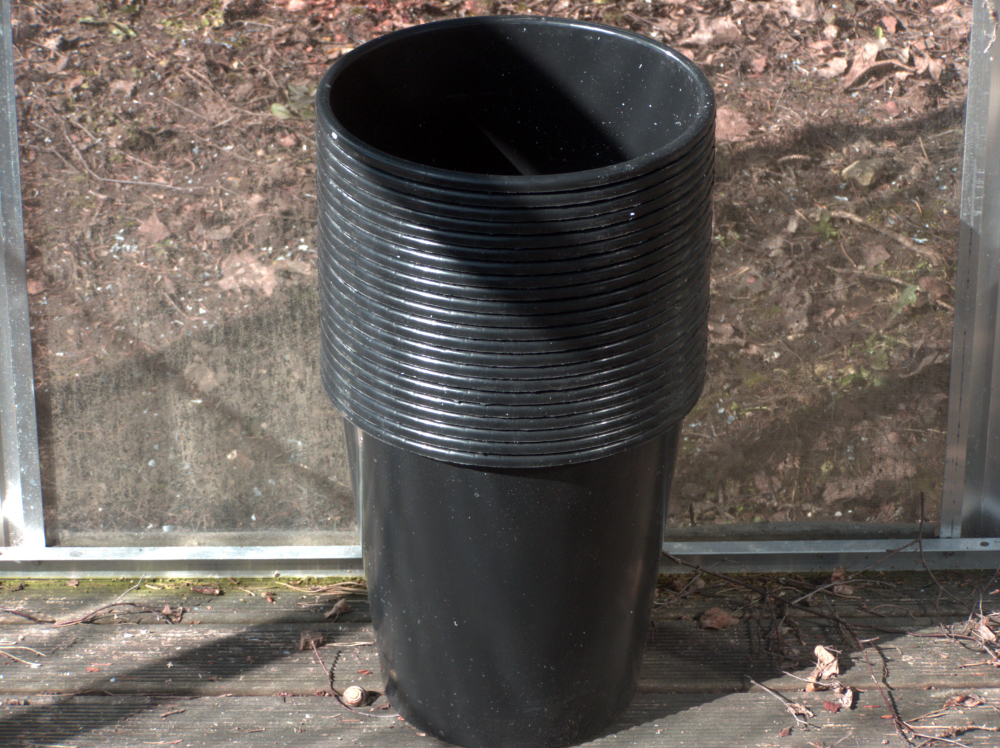
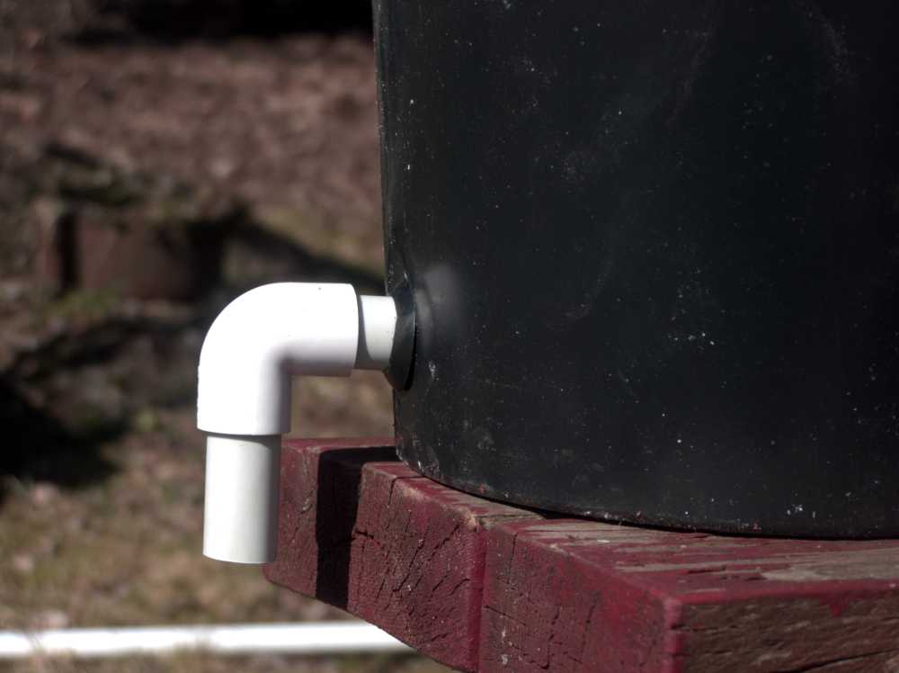
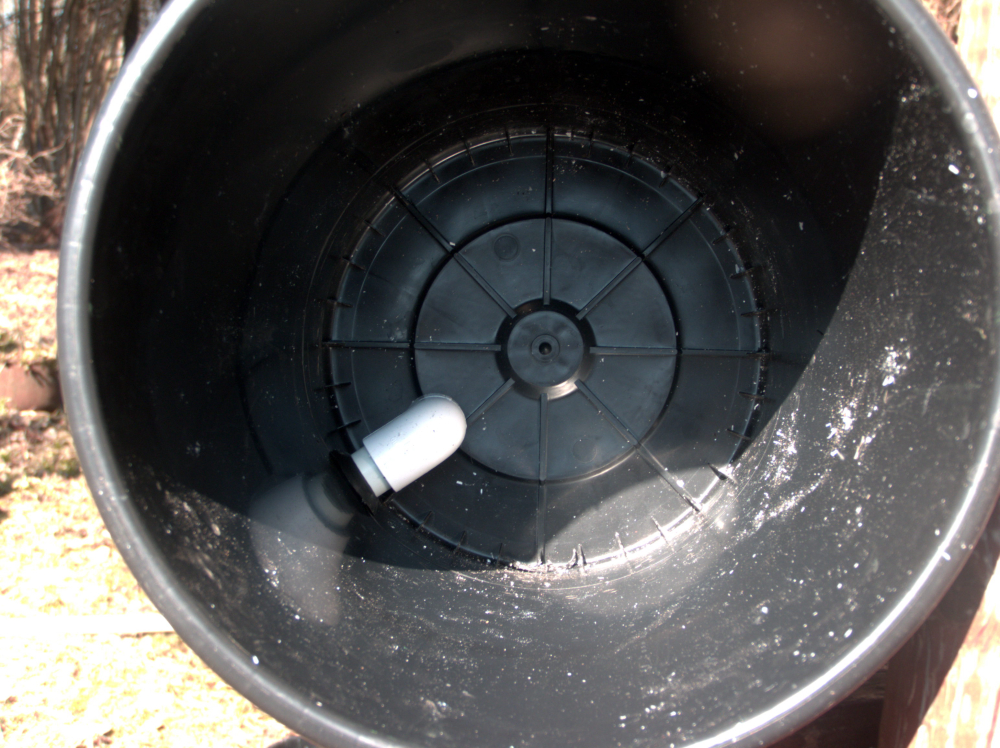
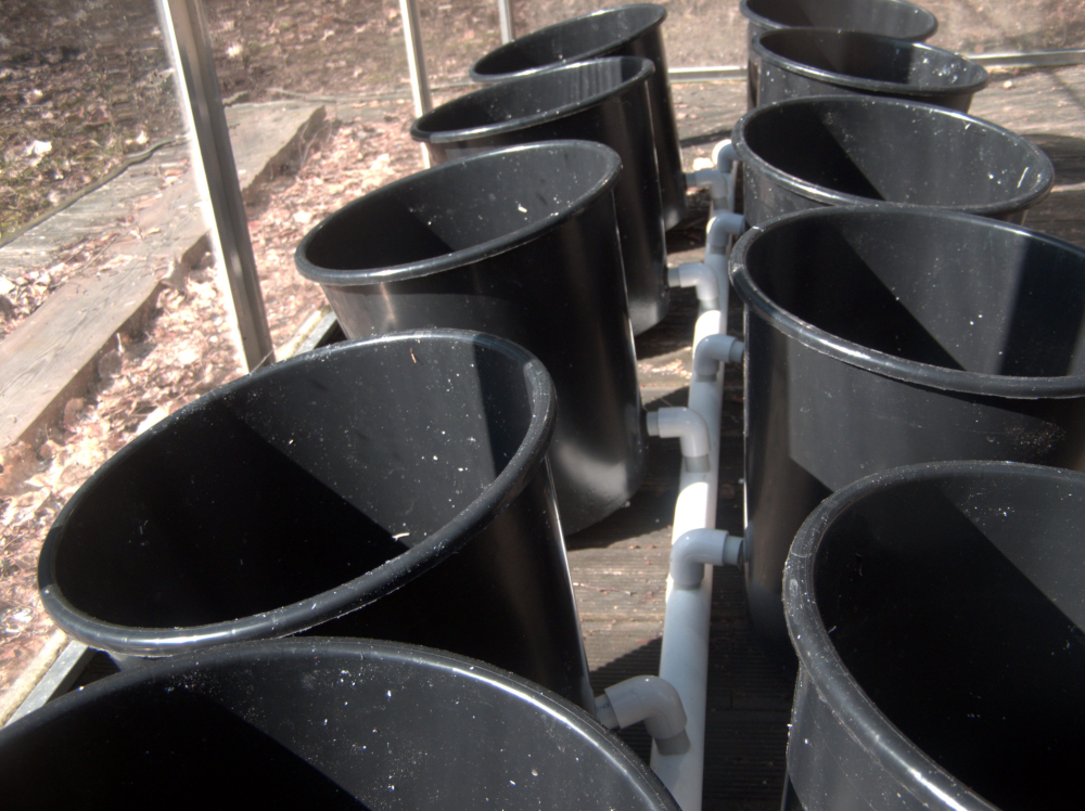
For tomatoes, peppers, cucumbers and other tall plants, people seem to prefer something like the Dutch bucket system. If you get buckets with lids, you can just drill a 2 inch hole for the plant to poke through and keep most of the rain out.
For smaller plants like leafy greens, herbs and such, the PVC pipe system seems great. You could set it up either as a NFT or a Flood&Drain system. The benefit again is that the rain water will not have a way into your nutrient solution.
-
To quote the classics - “Well, that escalated quickly.”
While waiting for the sensors to arrive, I started mulling over the entire project in my head. And I started thinking about scaling. My greenhouse is only 3 meters long but my parents greenhouse is almost 30 meters. Routing wires for soil sensors around the place is no fun.
So that got me thinking - does it need to be one node? And that in turn got me thinking - does it even have to be a node? Maybe a gateway would be the way to go?
So this is my current plan - a GSM/Wifi gateway with the general and more power hungry components( pH, EC, relative air humidity and ambient temp, relays). The gateway would be located near the pumps, sumps and other tech in the greenhouse.
Then the rest of the greenhouse can be filled with any number of sensors to monitor soil moisture, temperature and light levels at different places.
GSM gateway is almost finished, hopefully I can wrap it up tomorrow.
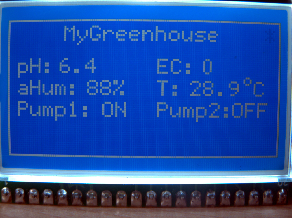
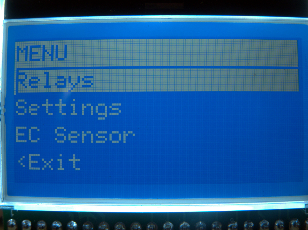
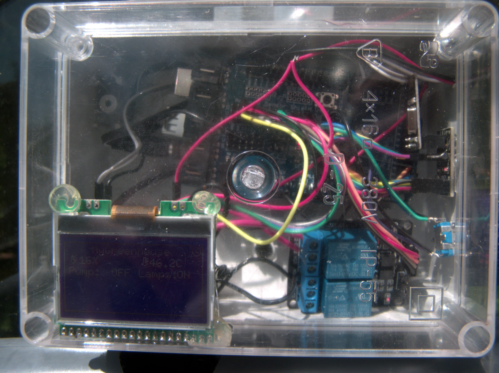
And as a final touch, I realized a controller of that kind of functionality could use a local user input. So it’s going to have a LCD and some buttons for set-up and things like starting/stopping pumps for maintenance.
-
Update:
LCD + rotary click encoder working
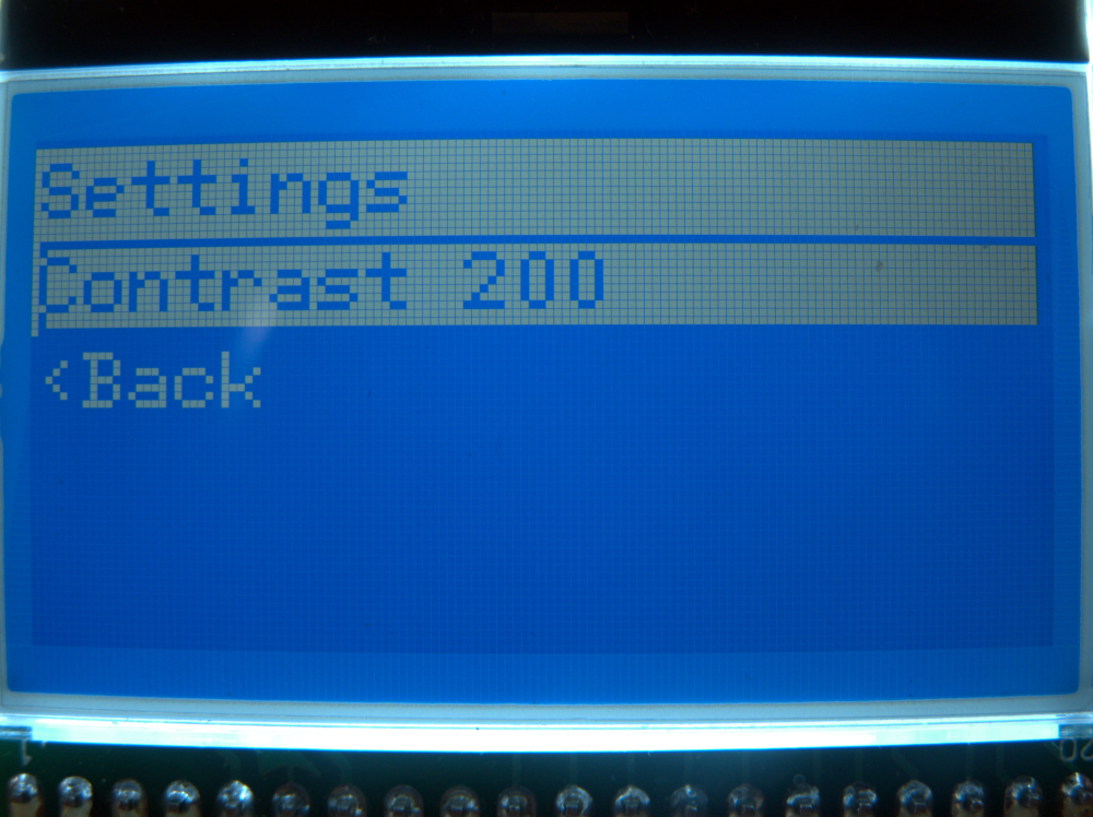
ArduinoMenu4 in place and easily expandable.
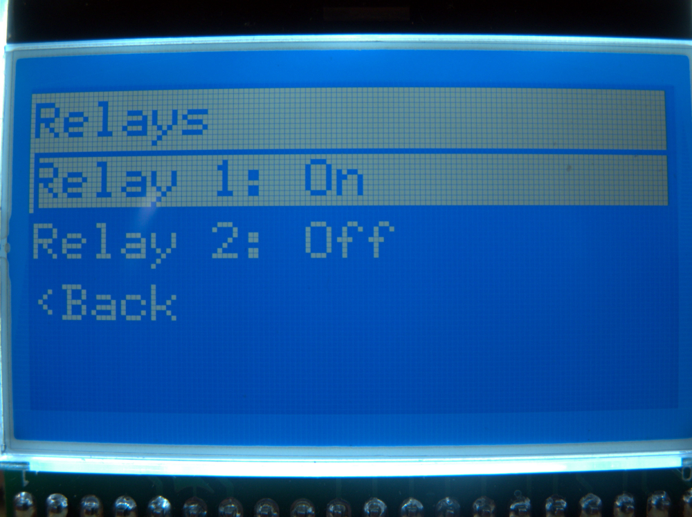
Relay control works 100%
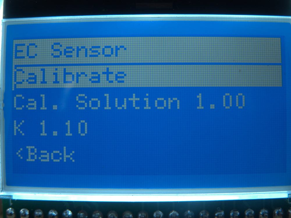
EC/ppm measurement in place, not yet 100% working
SHT21 code in place, can confirm if working or not once the darn thing arrivesSome eye candy:
-
A thought I had recently: Those moisture pitchforks are usually HASL coated. Do I really want that in the soil of a plant I probably want to eat? Any thoughts anyone?
@elcaron said in MySensors Hydroponics Greenhouse project:
A thought I had recently: Those moisture pitchforks are usually HASL coated. Do I really want that in the soil of a plant I probably want to eat? Any thoughts anyone?
The answer is no :)
-
@elcaron said in MySensors Hydroponics Greenhouse project:
HASL
The pitchfork i'm currently using has solid copper traces on the forks. For more long term use I'm planning on switching to capacitive soil moisture sensors. Those can be additionally coated with epoxy resin for example for added longevity.
-
Now that the GSM Gateway is done, I can start focusing more on the Greenhouse controller. I’m still waiting for the two most important components though - the pH sensor module and the stainless steel EC sensor probe. I’ve stumbled on another very good post on the EC topic which I’ll have to work through: https://thecavepearlproject.org/2017/08/12/measuring-electrical-conductivity-with-an-arduino-part1-overview/
-
A long overdue update.
In the end I basically ended up using a GSM gateway with a LCD and couple sensors (air temperature and air humidity) and two relays. The relays control my Dutch bucket system pump and ventilation fans.
As a separate sensor I'm using a Z-Wave multisensor to keep track of nursery temperatures and lux levels.
The pH meter module did arrive but I do not feel comfortable keeping it submerged in the nutrient solution at all times so I've been just taking a sample of the nutrient solution from the tank after mixing a new batch, and testing it indoors, at the computer.
As for the EC meter, I failed to get any of the "arduino only" examples to produce reliable readings. So I've ordered 5 PCB's for this thing: https://www.sparkyswidgets.com/portfolio-item/miniec-i2c-ec-interface/
Once they arrive, I'll see if I can get more reliable results with a separate module.So far the whole thing has been running almost perfectly. The only drawback is an occasional reboot of the gateway when switching off the Dutch bucket system pump. I'm using two separate power sources for Arduino and the pump, Added a 1000uF cap to the Arduino power rail and a flyback diode across the pumps power lines. Still getting that reboot about 50% of the time.
Some pics to wrap up my rant.
PS. Yes, that's a webcam in my greenhouse. It's taking hourly snapshots for a timelapse :)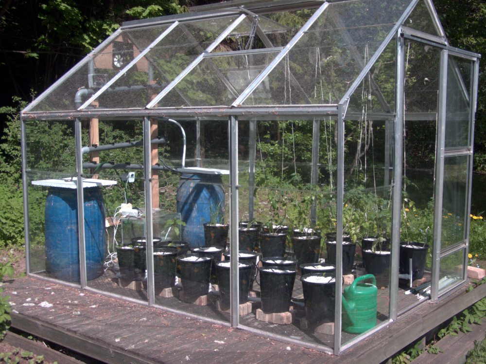
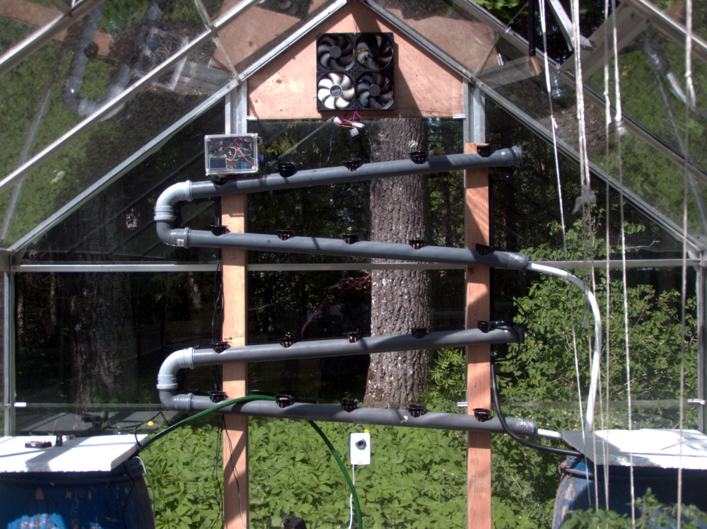
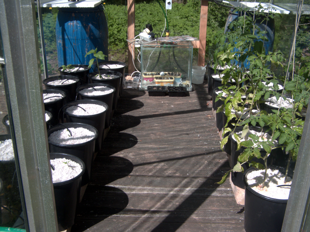
My NFT rails for herbs. A good eye can spot some dill, basil and cilantro plants in there.
That's my "Nursery" - an old fish tank I can cover with a piece of glass when night temps dip below 10C
That's my Fibaro Motion sensor. An easy way to get some essential readings. Like the length of day, hours of sunlight, temperature.
This is my ratsnest. I should have moved the relays to a separate enclosure further away. Right now I think the arc when breaking contact is what's causing an EMP pulse and rebooting my Mega.
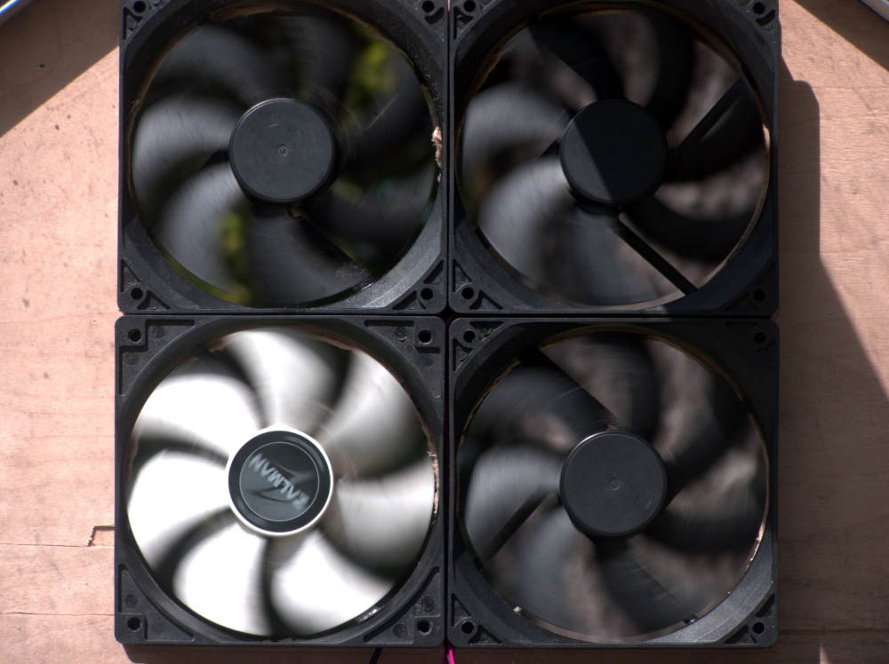
Ventilation fans. The temps soared to high 40's and low 50's with door and both ceiling hatches wide open. The fans kick in when air temp reaches 25C