nRF24Doctor

-
@rpx you need the development version of the mySensors library. 2.3.0 doesn't contain the functions for the received power detection graph yet.
The doctor will work with that line commented out, but the graph will stay empty. -
@Yveaux
Thank you very much for your answer.
I upload nRF24DoctorNode.ino with commented line and ... It work's ! But it don't see any of my three gateways one serial and two Ethernet W5100 which are all on work.
First I have to build a fourth one with the nRF24DoctorGateway.ino sketch.
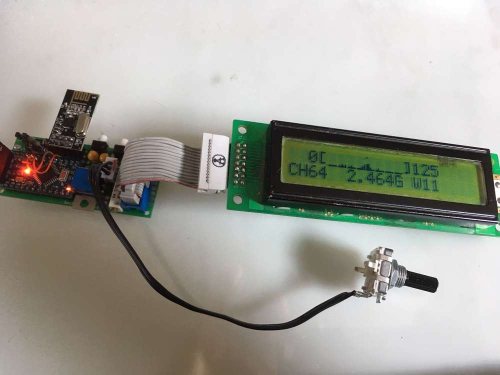
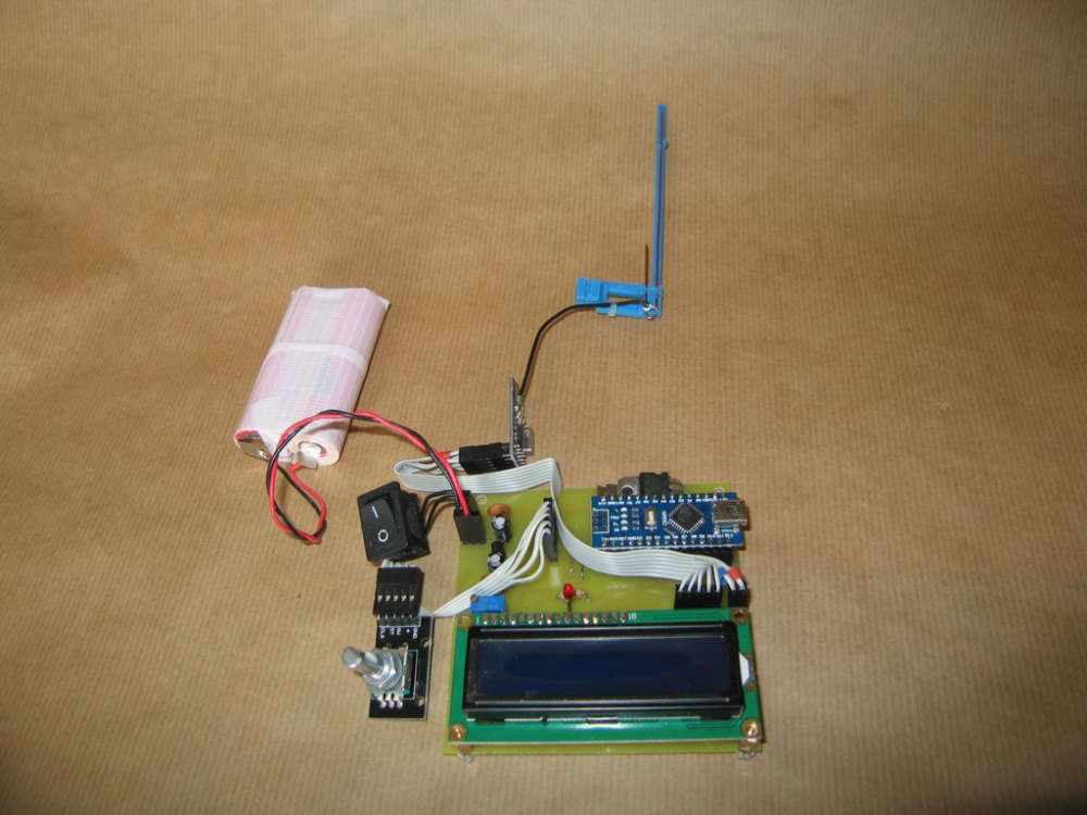
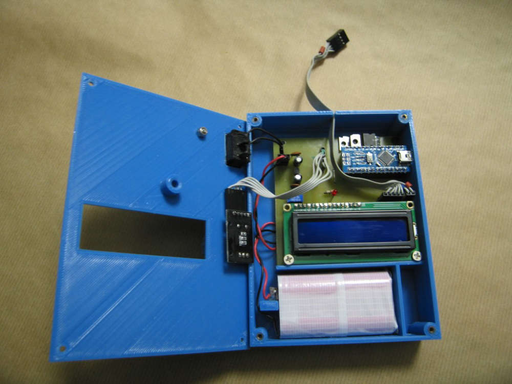
Some photos:
Front
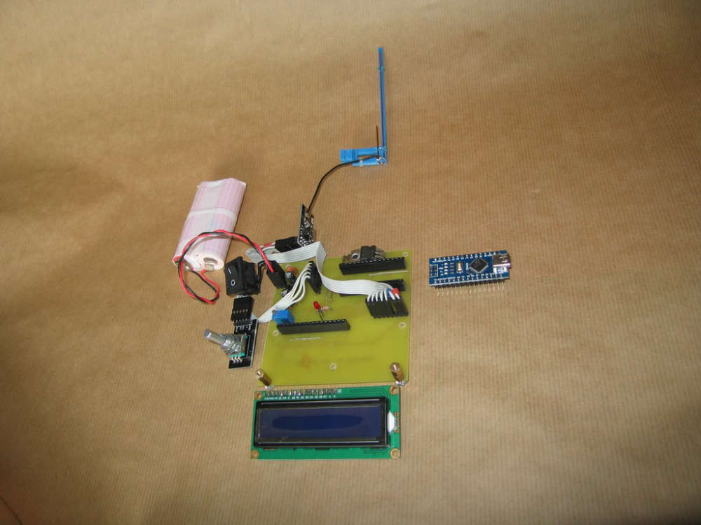
Front without Nano & LCD
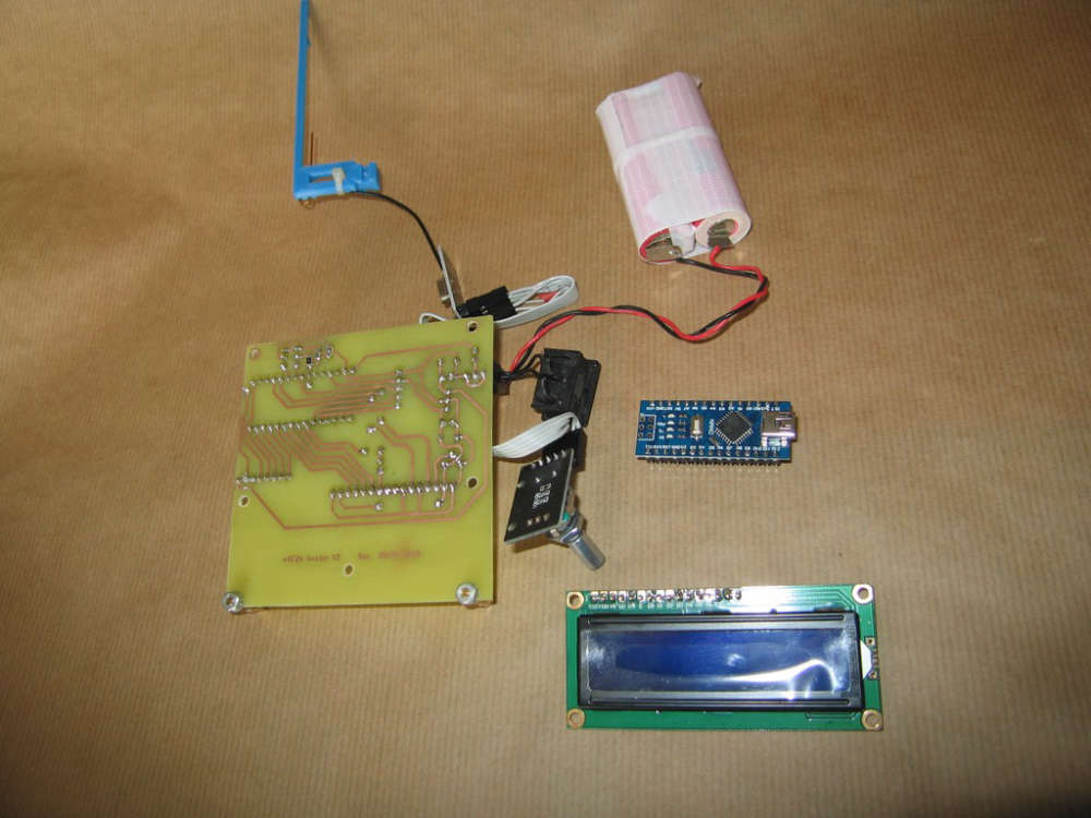
Back
KiKad schematics: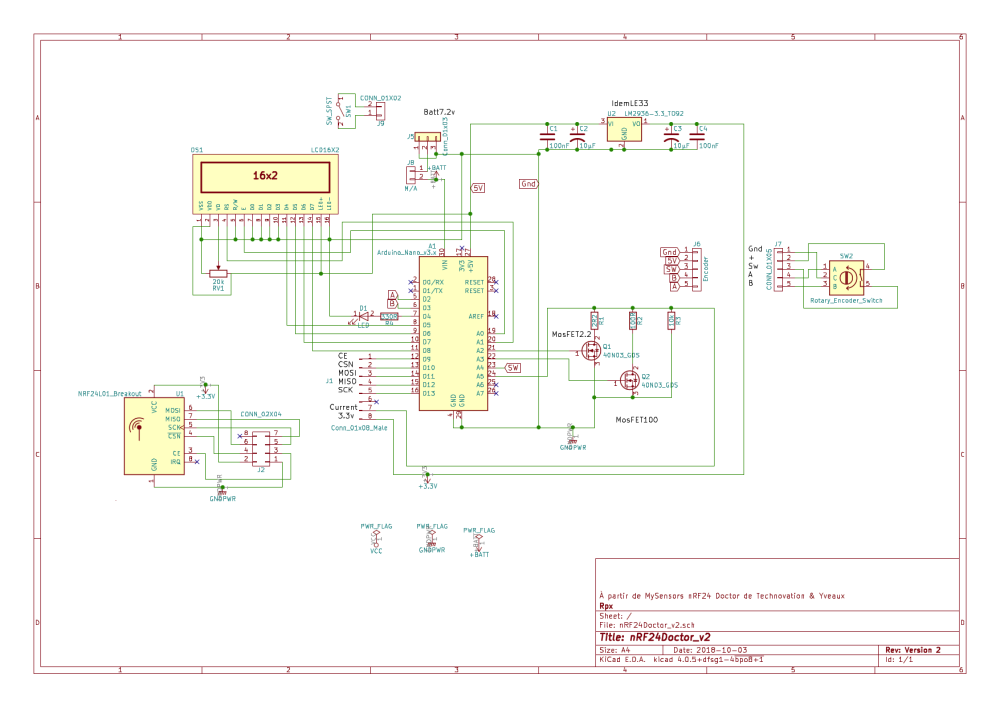
Pcb:
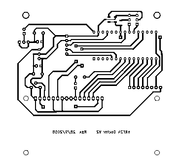
And LCD modifications:For D4 - D7 LCD #define LCD_D7 8 // 5 due to easier pcb design #define LCD_D6 7 // 6 #define LCD_D5 6 // 7 #define LCD_D4 5 // 8At last, I need to build an enclosure...
Rpx.
-
@rpx you need the development version of the mySensors library. 2.3.0 doesn't contain the functions for the received power detection graph yet.
The doctor will work with that line commented out, but the graph will stay empty. -
@yveaux Thanks !
One enclosure later...
I think about my three gateways weren't view.
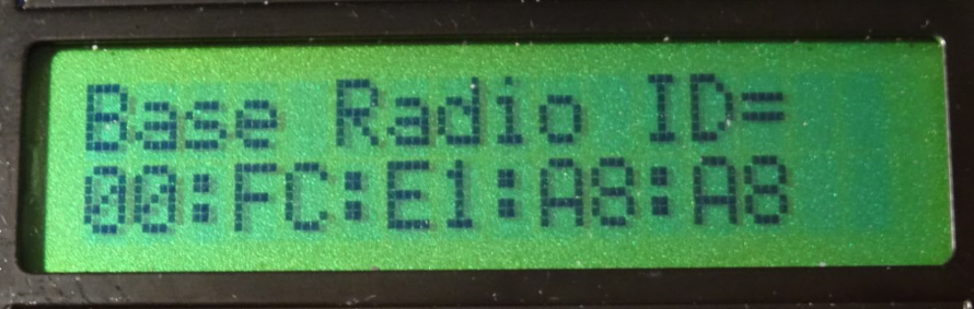
And made few adjustments.First in RadioConfig.h Ireplace "Zero CaFe BaBe" by my one of MY_RF24_BASE_RADIO_ID
/**
- @def MY_RF24_BASE_RADIO_ID
- @brief RF24 radio network identifier.
- This acts as base value for sensor nodeId addresses. Change this (or channel) if you have more
- than one sensor network.
*/
//0x00,0xCA,0xFE,0xBA,0xBE // modif Rpx de "Zero CaFe BaBe"
Second to be sure force selection of nRF24 CE on D9 and CS on D10
//PIN 9~13: NRF24 RADIO
#define MY_RF24_CE_PIN    (9)
#define MY_RF24_CS_PIN    (10)
And then Doctor is at work!
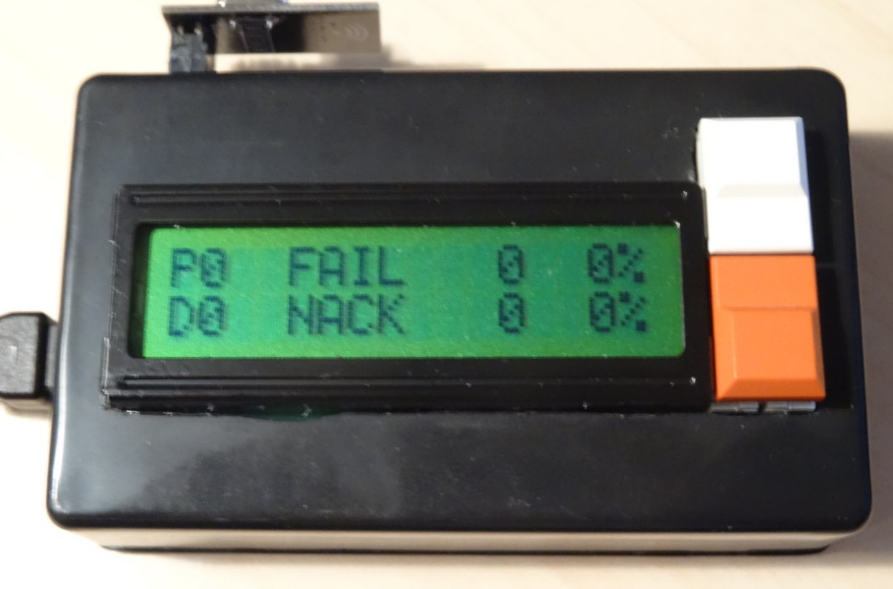
Enclosure Open
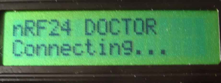
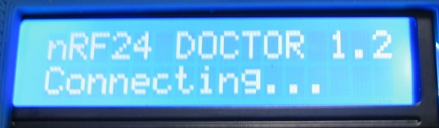
Connecting
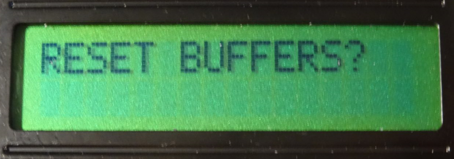
Msg
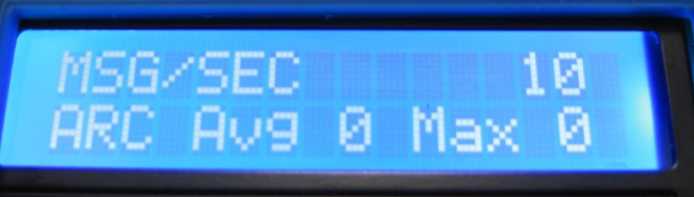
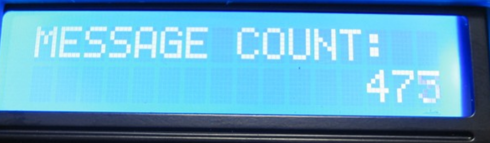
Message Count
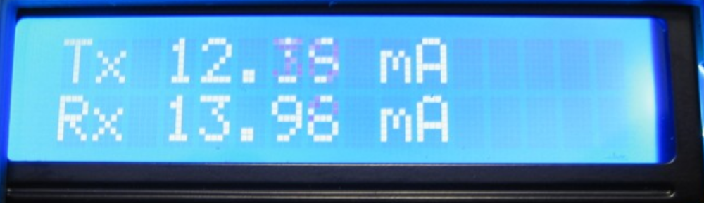
Tx Rx
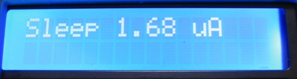
Sleep
Scan
At last, nRF24Doctor is working. Except scan due I think to use MySensors Library 2.2.0.
I don't know if a nRF24 PA LNA (20dBm) can be tested with nRF24Doctor but if my circuit design is used you should change LE33 witch output max 100mA because nRF24 PA LNA need 150mA min.
And one problem, a test with nRF24Doctor "freeze" Domoticz 3.8153, I need to stop service Domoticz and start to have a Domoticz web access.Thank you very much Yveaux.
Rpx. -
@yveaux Thanks !
One enclosure later...
I think about my three gateways weren't view.
And made few adjustments.First in RadioConfig.h Ireplace "Zero CaFe BaBe" by my one of MY_RF24_BASE_RADIO_ID
/**
- @def MY_RF24_BASE_RADIO_ID
- @brief RF24 radio network identifier.
- This acts as base value for sensor nodeId addresses. Change this (or channel) if you have more
- than one sensor network.
*/
//0x00,0xCA,0xFE,0xBA,0xBE // modif Rpx de "Zero CaFe BaBe"
Second to be sure force selection of nRF24 CE on D9 and CS on D10
//PIN 9~13: NRF24 RADIO
#define MY_RF24_CE_PIN    (9)
#define MY_RF24_CS_PIN    (10)
And then Doctor is at work!
Enclosure Open
Connecting
Msg
Message Count
Tx Rx
Sleep
Scan
At last, nRF24Doctor is working. Except scan due I think to use MySensors Library 2.2.0.
I don't know if a nRF24 PA LNA (20dBm) can be tested with nRF24Doctor but if my circuit design is used you should change LE33 witch output max 100mA because nRF24 PA LNA need 150mA min.
And one problem, a test with nRF24Doctor "freeze" Domoticz 3.8153, I need to stop service Domoticz and start to have a Domoticz web access.Thank you very much Yveaux.
Rpx.@rpx
@Yveaux OK with a nRF24 gateway it's working fine. But, and I don't remember why, I need to strap pin 8 of nRF24L01+ (Irq) to Nano Pin D2, which is not required on mysensors gateways.
And with MySensors Library 2.3.0 beta Scan is working.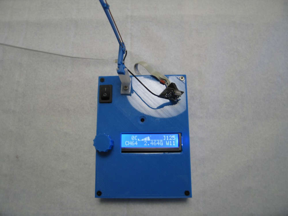
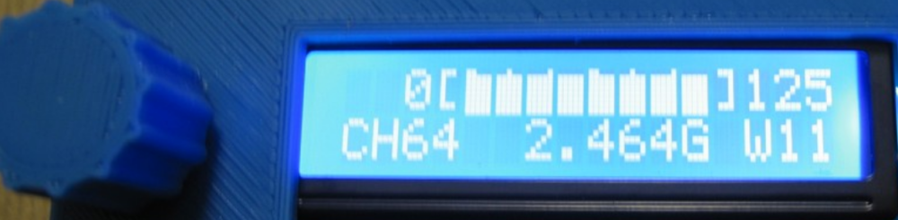
This pattern is a 950W microwave owen near by 0,60 meter.
The graph has 8 pixel high, can you give me a idea of the power scale of each pixel ?And I plan with friends help, to measure differents antennas in open field as J pole, Yagi-Uda and cloverleaf.
Rpx. -
@rpx
@Yveaux OK with a nRF24 gateway it's working fine. But, and I don't remember why, I need to strap pin 8 of nRF24L01+ (Irq) to Nano Pin D2, which is not required on mysensors gateways.
And with MySensors Library 2.3.0 beta Scan is working.
This pattern is a 950W microwave owen near by 0,60 meter.
The graph has 8 pixel high, can you give me a idea of the power scale of each pixel ?And I plan with friends help, to measure differents antennas in open field as J pole, Yagi-Uda and cloverleaf.
Rpx.@rpx said in nRF24Doctor:
The graph has 8 pixel high, can you give me a idea of the power scale of each pixel
Each time a carrier is detected on a channel the count for the channel is increased by 1, with a maximum of 255 per channel (per bucket really).
The top pixel of the chart gets set when the value is 128 or above, the next when 64 or above, then 32 etc. So kind of log2 logarithmic.
It makes the chart sensitive to small counts, but also displays larger values. -
@rpx said in nRF24Doctor:
The graph has 8 pixel high, can you give me a idea of the power scale of each pixel
Each time a carrier is detected on a channel the count for the channel is increased by 1, with a maximum of 255 per channel (per bucket really).
The top pixel of the chart gets set when the value is 128 or above, the next when 64 or above, then 32 etc. So kind of log2 logarithmic.
It makes the chart sensitive to small counts, but also displays larger values.This code is just great, Very good and impressive job.
While looking after recommendations for improving reliability of NRF24 links on easydomoticz french forum, @rpx put me through your NRFDoctor and I must admit is exceeds my expectations.
I just built it in few days and just starting to use it.
Tx/Rx statistic, Icc current measurements in sleep and operating modes, capabilities to reconfigure radio parameters between node and gateway, without forgeting the beautifull frequency range bar graph.
A perfect tool for Wifi and NRF links.
Many Thanks and regards
-
@rpx said in nRF24Doctor:
The graph has 8 pixel high, can you give me a idea of the power scale of each pixel
Each time a carrier is detected on a channel the count for the channel is increased by 1, with a maximum of 255 per channel (per bucket really).
The top pixel of the chart gets set when the value is 128 or above, the next when 64 or above, then 32 etc. So kind of log2 logarithmic.
It makes the chart sensitive to small counts, but also displays larger values. -
@benbidouille great to hear you like it!
Nice and compact build :+1:@Yveaux
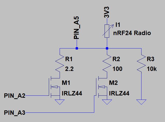
Can you confirm your design is operating well with NRF24 radio modules with High Icc current consumption up to 150 mA like with PA modules ?I mean is clear Rds ON of MOSfet is chosen as low as possible, but the voltage drop across the 2.2ohm shunt might becomes critical especially along transcients when radio operates.
I added Caps at Radio Supply rails ends and also Jumper for shorting shunt circuitry in case of.
Again very nice and well engineered design.
I used 20x2 display instead of 16x2, How painfull would you think it is to extend the graph display resolution ?
-
@Yveaux
Can you confirm your design is operating well with NRF24 radio modules with High Icc current consumption up to 150 mA like with PA modules ?I mean is clear Rds ON of MOSfet is chosen as low as possible, but the voltage drop across the 2.2ohm shunt might becomes critical especially along transcients when radio operates.
I added Caps at Radio Supply rails ends and also Jumper for shorting shunt circuitry in case of.
Again very nice and well engineered design.
I used 20x2 display instead of 16x2, How painfull would you think it is to extend the graph display resolution ?
@benbidouille said in nRF24Doctor:
I used 20x2 display instead of 16x2, How painfull would you think it is to extend the graph display resolution ?
The number of columns of the LCD display can be changed here.
You manually would have to change the lengths of fixed strings, like starting from here.
Could very well be that you start running into memory issues then, as the AVR is pretty packed.Regarding current measurements; the design & calculations were done by @Technovation, maybe he can chip in.
I can remember we struggled with grounding issues, as different Nanos have different quality in grounding, leading to deviations in measured current. We ended up manually patching a Nano to improve the ground layout. -
@benbidouille said in nRF24Doctor:
I used 20x2 display instead of 16x2, How painfull would you think it is to extend the graph display resolution ?
The number of columns of the LCD display can be changed here.
You manually would have to change the lengths of fixed strings, like starting from here.
Could very well be that you start running into memory issues then, as the AVR is pretty packed.Regarding current measurements; the design & calculations were done by @Technovation, maybe he can chip in.
I can remember we struggled with grounding issues, as different Nanos have different quality in grounding, leading to deviations in measured current. We ended up manually patching a Nano to improve the ground layout.@Yveaux
Thanks a lot for your feedback, and again very good collaborative job.The built-in starting and ending channel number capability even justifies to change nothing , it magnifies well the graph channel representation.
Yes I fully agree, by experience ADC measure and ground reference are critical on NANO.
Regards -
@Technovation, maybe he can chip in.
I can remember we struggled with grounding issues, as different Nanos have different quality in grounding, leading to deviations in measured current. We ended up manually patching a Nano to improve the ground layout.Indeed the depending on the nano board you may experience ground layout problems which are generally a problem for any accurate ADC measurement. The nano boards have GND pins on both left and right pin headers. In the poor designs they have no ground plane and simply use a thin trace to those pins. If you then have a bit of (varying) current draw flowing through those GND pins, the burden voltage on that thin trace will swing your GND reference for your ADC measurement up and down.
I mean is clear Rds ON of MOSfet is chosen as low as possible, but the voltage drop across the 2.2ohm shunt might becomes critical especially along transcients when radio operates.
The 2.2Ohm was a balance between current measurement resolution and the maximum current draw of a module during transmit. The worst case power consumption I measured was for a PA+LNA module at POWER = MAX (0dBm) setting and it consumed around 200mA bursts during transmit (these bursts are short and if you use a filtering cap it will average out those spikes to for example the 150mA you measured).
So a 2.2Ohm x 200mA = 0.44V drop.
Design considerations
- Drop out voltage nRF24:
This 0.44V will subtract from the 3V3 supply voltage to the nRF24 chip, leaving about 2.8V. According to the datasheet the nRF chip allows operation down to 2.7V for input signals >3.6V (e.g. 5V nano). - 3V3 Regulation
Also the voltage regulation to the nRF needs some attention. Using the 3V3 regulation from the nano itself may not suffice, because at some boards the voltage regulator will not be able to sustain a stable 3V3 at those current peaks. For that purpose there is the external regulator present. Here you may have to opt for a low drop-out regulator, because a "standard" regulators drop out voltage will typically be 1.2V or larger and will not have sufficient voltage available in combo with the 0.44V burden voltage is in this budget: 3V3 output regulation + 0.44Vdrop + 1.2V regulation margin > 5V input to regulator.
So all and all the design should be able to handle the PA+LNA in the worst case conditions (max power) and it did with all the units I tested, but it may require a bit of attention in the regulation. However some attention to the supply regulation is in general required with the PA+LNA variants in any design.
- Drop out voltage nRF24:
-
@Technovation, maybe he can chip in.
I can remember we struggled with grounding issues, as different Nanos have different quality in grounding, leading to deviations in measured current. We ended up manually patching a Nano to improve the ground layout.Indeed the depending on the nano board you may experience ground layout problems which are generally a problem for any accurate ADC measurement. The nano boards have GND pins on both left and right pin headers. In the poor designs they have no ground plane and simply use a thin trace to those pins. If you then have a bit of (varying) current draw flowing through those GND pins, the burden voltage on that thin trace will swing your GND reference for your ADC measurement up and down.
I mean is clear Rds ON of MOSfet is chosen as low as possible, but the voltage drop across the 2.2ohm shunt might becomes critical especially along transcients when radio operates.
The 2.2Ohm was a balance between current measurement resolution and the maximum current draw of a module during transmit. The worst case power consumption I measured was for a PA+LNA module at POWER = MAX (0dBm) setting and it consumed around 200mA bursts during transmit (these bursts are short and if you use a filtering cap it will average out those spikes to for example the 150mA you measured).
So a 2.2Ohm x 200mA = 0.44V drop.
Design considerations
- Drop out voltage nRF24:
This 0.44V will subtract from the 3V3 supply voltage to the nRF24 chip, leaving about 2.8V. According to the datasheet the nRF chip allows operation down to 2.7V for input signals >3.6V (e.g. 5V nano). - 3V3 Regulation
Also the voltage regulation to the nRF needs some attention. Using the 3V3 regulation from the nano itself may not suffice, because at some boards the voltage regulator will not be able to sustain a stable 3V3 at those current peaks. For that purpose there is the external regulator present. Here you may have to opt for a low drop-out regulator, because a "standard" regulators drop out voltage will typically be 1.2V or larger and will not have sufficient voltage available in combo with the 0.44V burden voltage is in this budget: 3V3 output regulation + 0.44Vdrop + 1.2V regulation margin > 5V input to regulator.
So all and all the design should be able to handle the PA+LNA in the worst case conditions (max power) and it did with all the units I tested, but it may require a bit of attention in the regulation. However some attention to the supply regulation is in general required with the PA+LNA variants in any design.
Many thanks for your highlights.
Yes fully agreed that unfortunatly cheap NANO or PRO MINI does not have state of the art PCB design rules with ground planes.
Supply of NRF24 is requiring also a lot of attention in power rails that shall be as much as possible decoupled from the digital supply of the Arduino, better to have an external low drop out voltage regulator as you mentionned earlier.
For the 3.3V regulation and voltage drop, I do not follow you, to me we have 3.3V output regulation + 1,2V regulation margin which remains well under the 5V input of the regulator ( doesn't includes the 0,44v drop )
The Voltage drop accross the 2,2 ohm shunt is on the ground path of the 3,3V regulator so the NRF24 is seing only 3,3V - 0,44V on worse case TX condition and considering rdson is neglectable against the shunt.
From the NRF24, Radio can even operate with down to 1,9V supply, surprisingly very tolerant.
In my circuit I placed a jumper for shorting the shunt and fullfill a 3.3V supply.
After some trials today up to 154mA , I can confirm the voltage drop has absolutly no effect to radio TX/RX quality, so my jumper is useless, but I always prefer to put it in place for all expect power and sleep measurement.
Again great job you all did.
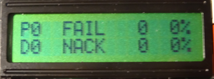
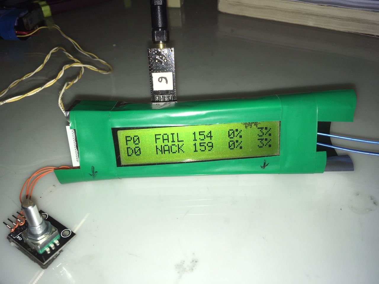
Just a question related to Statistics, What is the FAIL and NACK % corresponding to ?
It never exceeds few % even so the transmission is continiously failing. - Drop out voltage nRF24:
-
Many thanks for your highlights.
Yes fully agreed that unfortunatly cheap NANO or PRO MINI does not have state of the art PCB design rules with ground planes.
Supply of NRF24 is requiring also a lot of attention in power rails that shall be as much as possible decoupled from the digital supply of the Arduino, better to have an external low drop out voltage regulator as you mentionned earlier.
For the 3.3V regulation and voltage drop, I do not follow you, to me we have 3.3V output regulation + 1,2V regulation margin which remains well under the 5V input of the regulator ( doesn't includes the 0,44v drop )
The Voltage drop accross the 2,2 ohm shunt is on the ground path of the 3,3V regulator so the NRF24 is seing only 3,3V - 0,44V on worse case TX condition and considering rdson is neglectable against the shunt.
From the NRF24, Radio can even operate with down to 1,9V supply, surprisingly very tolerant.
In my circuit I placed a jumper for shorting the shunt and fullfill a 3.3V supply.
After some trials today up to 154mA , I can confirm the voltage drop has absolutly no effect to radio TX/RX quality, so my jumper is useless, but I always prefer to put it in place for all expect power and sleep measurement.
Again great job you all did.
Just a question related to Statistics, What is the FAIL and NACK % corresponding to ?
It never exceeds few % even so the transmission is continiously failing.I do not follow you, to me we have 3.3V output regulation + 1,2V regulation margin which remains well under the 5V input of the regulator ( doesn't includes the 0,44v drop )
You're right. I knew there was something additional in the order of about that shunt voltage drop, but should have checked the layout to spark my memory a bit better. It is not the voltage drop of the shunt but if you use the 5V output from the nano board you may have to account for a reverse voltage protection diode that may be present (i.e. your 5V pin does not really 5V). That's why there is a jumper to directly supply from the Vin pin.
What is the FAIL and NACK % corresponding to
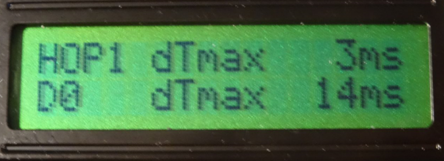
- As in the description with the first post it should report percentage of FAILED acknowledges for the first HOP transmit (if no repeater nodes are present, then the first HOP will be the Gateway). This is actually the confirmation at "nrf24 radio level" to report if the message was received by another radio.
- NACK : The gateway is requested an ACK message for every message the node transmits. So that means the round trip of the message from NODE-> GATEWAY -> NODE.
So it can be that you have no FAIL but a lot of NACK, which would mean that your test node can send out a message and was received by another radio, but never receives an ACK back for the transmitted message.
-
I do not follow you, to me we have 3.3V output regulation + 1,2V regulation margin which remains well under the 5V input of the regulator ( doesn't includes the 0,44v drop )
You're right. I knew there was something additional in the order of about that shunt voltage drop, but should have checked the layout to spark my memory a bit better. It is not the voltage drop of the shunt but if you use the 5V output from the nano board you may have to account for a reverse voltage protection diode that may be present (i.e. your 5V pin does not really 5V). That's why there is a jumper to directly supply from the Vin pin.
What is the FAIL and NACK % corresponding to
- As in the description with the first post it should report percentage of FAILED acknowledges for the first HOP transmit (if no repeater nodes are present, then the first HOP will be the Gateway). This is actually the confirmation at "nrf24 radio level" to report if the message was received by another radio.
- NACK : The gateway is requested an ACK message for every message the node transmits. So that means the round trip of the message from NODE-> GATEWAY -> NODE.
So it can be that you have no FAIL but a lot of NACK, which would mean that your test node can send out a message and was received by another radio, but never receives an ACK back for the transmitted message.
@Technovation
Many Thanks for your feedback, Yes we are fully in line, including the forward diode junction on the 5V.About the NACK and FAIL this is very clear to me for the absolute value but I was wondering for Percentage value.
I'm actually doing transmission benchmarks ( combining different radios, radio shields etc .... under exact same conditions ) over periods of 5 minutes with payloads of 2 and 100 Msg/s, and I thought the percentage shown corresponds to Nbr_of_fail / Total_Counter, but it is not and i assume percentage is rather calculated over last X.
This is a very very good tools, I really appreciate, OEM NRF24 module are not all the same some are much better than others.
Best Regards -
@Technovation
Many Thanks for your feedback, Yes we are fully in line, including the forward diode junction on the 5V.About the NACK and FAIL this is very clear to me for the absolute value but I was wondering for Percentage value.
I'm actually doing transmission benchmarks ( combining different radios, radio shields etc .... under exact same conditions ) over periods of 5 minutes with payloads of 2 and 100 Msg/s, and I thought the percentage shown corresponds to Nbr_of_fail / Total_Counter, but it is not and i assume percentage is rather calculated over last X.
This is a very very good tools, I really appreciate, OEM NRF24 module are not all the same some are much better than others.
Best Regards@benbidouille said in nRF24Doctor:
I thought the percentage shown corresponds to Nbr_of_fail / Total_Counter, but it is not and i assume percentage is rather calculated over last X
It is indeed calculated over the last 100 msg's. In that way you have some "real-time" feedback on your connection quality (i.e. suppose you would have had 10.000 good msg's and it would start to fail - it will take +/-100 failed msg's to drop a single 1%).
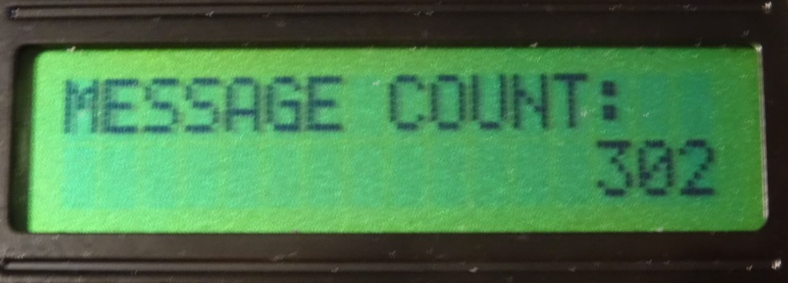
You can calculate the percentage based on the total nr of msg's by getting the total MESSAGE COUNT displayed at Counters page and combine that with the values from FAIL and NACK on the Statistics page.
-
@benbidouille said in nRF24Doctor:
I thought the percentage shown corresponds to Nbr_of_fail / Total_Counter, but it is not and i assume percentage is rather calculated over last X
It is indeed calculated over the last 100 msg's. In that way you have some "real-time" feedback on your connection quality (i.e. suppose you would have had 10.000 good msg's and it would start to fail - it will take +/-100 failed msg's to drop a single 1%).
You can calculate the percentage based on the total nr of msg's by getting the total MESSAGE COUNT displayed at Counters page and combine that with the values from FAIL and NACK on the Statistics page.
@Technovation
Many thanks, I took opportunity of the only oversized 20x2 LCD device I had, to add the Nbr_of_fail / Total_Counter statistics display, very useful for cumulative % on long run in addition to original last 100 msg.I also wanted to share with you importance of having a proper shielding (underneath green tape is aluminium film) where only Radio OEM module is exposed.
Under PA+LNA in the worst case conditions (max power), shielding significantly increases TX RX reliability (ideally OEM module body should also be shielded)
Cheers
-
@Technovation
Many thanks, I took opportunity of the only oversized 20x2 LCD device I had, to add the Nbr_of_fail / Total_Counter statistics display, very useful for cumulative % on long run in addition to original last 100 msg.I also wanted to share with you importance of having a proper shielding (underneath green tape is aluminium film) where only Radio OEM module is exposed.
Under PA+LNA in the worst case conditions (max power), shielding significantly increases TX RX reliability (ideally OEM module body should also be shielded)
Cheers
Hello,
This is me again
I intended to modify my existing W5100 GW to incorporate Doctor features, W5100 based on an Arduino NANO but I'm facing an architecture issue.Mysensor recommends W5100 GW to use a Soft SPI for the NRF24 Radio as seems W5100 and NRF24 both on same SPI bus fails to operate.
GW Doctor requires IRQ which Soft SPI doesn't support, so sketch fails to compile with below error.
#error RF24 IRQ usage cannot be used with Soft SPI
Has somebody worked-around that situation and succeded to have a W5100 Doctor GW ?
Thanks in advance
-
Hello,
This is me again
I intended to modify my existing W5100 GW to incorporate Doctor features, W5100 based on an Arduino NANO but I'm facing an architecture issue.Mysensor recommends W5100 GW to use a Soft SPI for the NRF24 Radio as seems W5100 and NRF24 both on same SPI bus fails to operate.
GW Doctor requires IRQ which Soft SPI doesn't support, so sketch fails to compile with below error.
#error RF24 IRQ usage cannot be used with Soft SPI
Has somebody worked-around that situation and succeded to have a W5100 Doctor GW ?
Thanks in advance
@benbidouille you can run W5100 with hardware spi but there are many revisions of the W5100 arduino shield available. Some of them eg require to have a defined state of the SD card select line before mySensors starts. Not a big problem, but you need to understand your hardware.
That's why soft spi is suggested.