nRF24Doctor

-
Very cool!
Just thinking out loud: Would it be an idea to create a 'light' version of this that could be loaded onto a bare node, without any sensors/screens, and that would output details over serial? For beginners it might be a bit much to invest in so much hardware. But the core functionality is awesome!
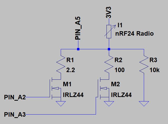
@alowhum well, the schematic is more or less the bare minimum. Even with current measurement the number of components and total cost is very low ($10 ballpark).
This project is a continuous development and I'm designing a pcb for it at the moment (all through - hole, so easy to replicate).
The output of the display could also be sent over serial, but the whole idea is you can walk around with the doctor and improve your results as you go. -
@Technovation , thanks for diagnostics tool. Could you help to interpret the results what I get?
When I am at ~7m range, I nrf24doctor node shows no faults and gateway produces all nice log:
250;0;1;0;48;17
0;255;3;0;9;227401 TSF:MSG:READ,250-250-0,s=0,c=1,t=48,pt=3,l=2,sg=0:18
0;255;3;0;9;227408 TSF:MSG:ACK REQ
0;255;3;0;9;227418 TSF:MSG:SEND,0-0-250-250,s=0,c=1,t=48,pt=3,l=2,sg=0,ft=0,st=OK:18When distance increases, nrf24doctor node shows 1-2 percent of faults, but the log on the gateway consistently shows NACK's:
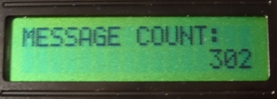
250;0;1;0;48;322
0;255;3;0;9;558810 TSF:MSG:READ,250-250-0,s=0,c=1,t=48,pt=3,l=2,sg=0:323
0;255;3;0;9;558817 TSF:MSG:ACK REQ
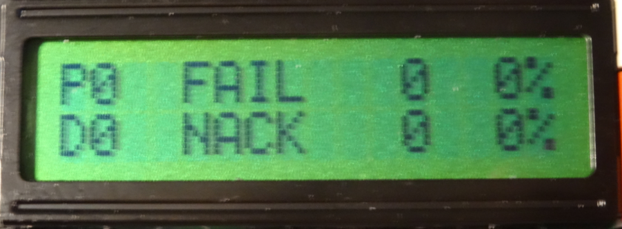
0;255;3;0;9;558856 !TSF:MSG:SEND,0-0-250-250,s=0,c=1,t=48,pt=3,l=2,sg=0,ft=0,st=NACK:323So do I read it right way, that my node manages to deliver to gateway the message with payload, but fails to deliver the ACK?
How that works? How do I understand results like this?
thanks,
-
And finally PART3 the sketch for the nRF24DoctorGateway
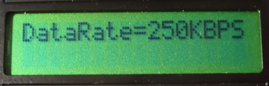
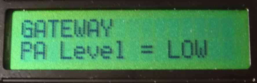
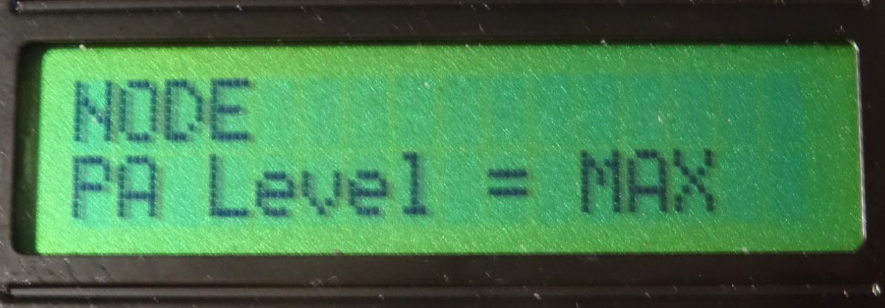
/**
* The MySensors Arduino library handles the wireless radio link and protocol
* between your home built sensors/actuators and HA controller of choice.
* The sensors forms a self healing radio network with optional repeaters. Each
* repeater and gateway builds a routing tables in EEPROM which keeps track of the
* network topology allowing messages to be routed to nodes.
*
* Created by Henrik Ekblad <henrik.ekblad@mysensors.org>
* Copyright (C) 2013-2015 Sensnology AB
* Full contributor list: https://github.com/mysensors/Arduino/graphs/contributors
*
* Documentation: http://www.mysensors.org
* Support Forum: http://forum.mysensors.org
*
* This program is free software; you can redistribute it and/or
* modify it under the terms of the GNU General Public License
* version 2 as published by the Free Software Foundation.
*
*******************************
*
* DESCRIPTION
* The ArduinoGateway prints data received from sensors on the serial link.
* The gateway accepts input on seral which will be sent out on radio network.
*
* The GW code is designed for Arduino Nano 328p / 16MHz
*
* Wire connections (OPTIONAL):
* - Inclusion button should be connected between digital pin 3 and GND
* - RX/TX/ERR leds need to be connected between +5V (anode) and digital pin 6/5/4 with resistor 270-330R in a series
*
* LEDs (OPTIONAL):
* - To use the feature, uncomment any of the MY_DEFAULT_xx_LED_PINs
* - RX (green) - blink fast on radio message recieved. In inclusion mode will blink fast only on presentation recieved
* - TX (yellow) - blink fast on radio message transmitted. In inclusion mode will blink slowly
* - ERR (red) - fast blink on error during transmission error or recieve crc error
*
*/

//---------------- SET SPECIFIC MY SENSORS SETTINGS ---------------------//

// Enable debug prints to serial monitor
#define MY_DEBUG
#define MY_DEBUG_VERBOSE_SIGNING

// Enable and select radio type attached
#define MY_RADIO_NRF24


//#define MY_RF24_CHANNEL 1
//#define MY_RF24_DATARATE RF24_1MBPS

//If you are using an Arduino Mega
#define MY_RF24_CE_PIN 49
#define MY_RF24_CS_PIN 53
//Enable receiving buffer feature.
//#define MY_RF24_IRQ_PIN 2
//#define MY_RX_MESSAGE_BUFFER_FEATURE

// Set LOW transmit power level as default, if you have an amplified NRF-module and
// power your radio separately with a good regulator you can turn up PA level.
#define MY_RF24_PA_LEVEL RF24_PA_MAX

// Signing settings
//#define MY_SIGNING_SOFT
//#define MY_SIGNING_SOFT_RANDOMSEED_PIN 7
//#define MY_SIGNING_REQUEST_SIGNATURES
//These codes should be programmed in EEPROM through SecurityPersonalizer.ino with USB connection once (will be maintained with reprogramming of new sketches) and preferably not send over the air)
//#define MY_SOFT_HMAC_KEY 0xFC,0x7E,0xA0,0x9F,0xEA,0x20,0x14,0xD0,0xC4,0x5F,0xBB,0xA3,0x70,0xE8,0xA1,0xDD,0x72,0x3E,0xBB,0x19,0x50,0x8E,0x35,0x7D,0x44,0x25,0xBB,0x7A,0xF4,0xAA,0x28,0x76
//#define MY_SOFT_SERIAL 0x2C,0xA0,0x3F,0x21,0x08,0x80,0xF5,0x8A,0xC4
//#define MY_AES_KEY 0x8F,0x87,0x9B,0x25,0xEE,0xAC,0x6A,0x36,0x3D,0xD3,0xF8,0x35,0x5F,0xD5,0xCB,0x96

// RF24 encryption is enabled in MyConfig.h (all nodes and gateway must have this enabled, and all must be personalized with the same AES key)
//#define MY_RF24_ENABLE_ENCRYPTION

// Enable serial gateway
#define MY_GATEWAY_SERIAL
// Define a lower baud rate for Arduino's running on 8 MHz (Arduino Pro Mini 3.3V & SenseBender)
#if F_CPU == 8000000L
#define MY_BAUD_RATE 38400
#endif

// Enable inclusion mode
#define MY_INCLUSION_MODE_FEATURE
// Enable Inclusion mode button on gateway
#define MY_INCLUSION_BUTTON_FEATURE

// Inverses behavior of inclusion button (if using external pullup)
//#define MY_INCLUSION_BUTTON_EXTERNAL_PULLUP

// Set inclusion mode duration (in seconds)
#define MY_INCLUSION_MODE_DURATION 60
// Digital pin used for inclusion mode button
#define MY_INCLUSION_MODE_BUTTON_PIN  3

// Set blinking period
#define MY_DEFAULT_LED_BLINK_PERIOD 300

// Inverses the behavior of leds
//#define MY_WITH_LEDS_BLINKING_INVERSE

// Flash leds on rx/tx/err
// Uncomment to override default HW configurations
#define MY_DEFAULT_ERR_LED_PIN 4  // Error led pin
#define MY_DEFAULT_TX_LED_PIN  5  // the PCB, on board LED
#define MY_DEFAULT_RX_LED_PIN  6  // Receive led pin

//**** MySensors Messages ****
#define MY_TRANSPORT_SANITY_CHECK_INTERVAL_MS 3000000000			//To Prevent the MySensors library from resetting back to default radio settings
#include <MySensors.h>
#define CHILD_ID_UPDATE_GATEWAY 250
MyMessage MsgUpdateGateway(CHILD_ID_UPDATE_GATEWAY, V_CUSTOM);   	//Send value for Gateway settings: xxxyz (xxx = Channel, y = PaLevel, z = DataRate)
uint8_t iRf24Channel 		= MY_RF24_CHANNEL;
uint8_t iRf24PaLevelGw 		= MY_RF24_PA_LEVEL;
uint8_t iRf24DataRate 		= MY_RF24_DATARATE;
bool bLoadNewRadioSettings 	= 0;
const uint8_t iNrPaLevels = 4;
const char *pcPaLevelNames[iNrPaLevels] 		= { "MIN", "LOW", "HIGH", "MAX" };
const uint8_t iNrDataRates = 3;
const char *pcDataRateNames[iNrDataRates] 		= { "1MBPS", "2MBPS" , "250KBPS"};
#define DELAY_BETWEEN_RADIO_SETTINGS_PRINT 20000	//Print Radio Settings to Serial Monitor every x[ms]

//**** DEBUG *****
#define LOCAL_DEBUG

#ifdef LOCAL_DEBUG
#define Sprint(a) (Serial.print(a))           	// macro as substitute for print, enable if no print wanted
#define Sprintln(a) (Serial.println(a))
#else											// macro for "no" debug print
#define Sprint(a)
#define Sprintln(a)
#endif


//-----------------------------------------------------------------------//


void setup()
{
	//loadNewRadioSettings();	//Load the Radio Settings as transmitted by the nRF24 Doctor Node
}

void presentation()
{
	// Present locally attached sensors
}

void loop()
{
	static unsigned long lLastRadioSettingsPrint = millis();
	wait(1);
	//Set new Radio settings by nRF24 Doctor Node
	if (bLoadNewRadioSettings){
		bLoadNewRadioSettings = 0;
		loadNewRadioSettings();
	}
	//Regularly print the Radio Settings we are using
	if ((millis()- lLastRadioSettingsPrint) > DELAY_BETWEEN_RADIO_SETTINGS_PRINT){// wait for things to settle and ack's to arrive
		lLastRadioSettingsPrint = millis();
		PrintRadioSettings();
	}
}

/*****************************************************************************/
/************************ RECEIVE & TRANSMIT FUNCTIONS ***********************/
/*****************************************************************************/
void receive(const MyMessage &message) {
	if (message.type == V_CUSTOM && message.sensor==CHILD_ID_UPDATE_GATEWAY){	//Acknowledge message & of correct type & Sensor
		uint16_t iNewMessage = message.getUInt();           // get received value
		//Extract the new Gateway settings
		iRf24Channel 	= (uint16_t)(iNewMessage/100U);
		iRf24PaLevelGw 	= (uint16_t)((iNewMessage/10U)%10);
		iRf24DataRate 	= (uint16_t)(iNewMessage%10);
		bLoadNewRadioSettings = 1;
		Sprintln("Received new Radio settings.");
	}
}

/********************************************************************************/
/************************ CONFIGURE nRF24 RADIO FUNCTIONS ***********************/
/********************************************************************************/
void loadNewRadioSettings() {
	uint8_t rfsetup = ( ((iRf24DataRate & 0b10 ) << 4) | ((iRf24DataRate & 0b01 ) << 3) | (iRf24PaLevelGw << 1) ) + 1;		//!< RF24_RF_SETUP, +1 for Si24R1 and LNA
	RF24_setChannel(iRf24Channel);
	RF24_setRFSetup(rfsetup);
	RF24_enableFeatures();
	Sprint("Updated Radio Settings!\t");
	PrintRadioSettings();
}

/********************************************************************************/
/******************************** SERIAL OUTPUT *********************************/
/********************************************************************************/
void PrintRadioSettings() {
	Sprint("Channel:");Sprint(iRf24Channel);Sprint("\t");
	Sprint("PaLevel:");Sprint(pcPaLevelNames[iRf24PaLevelGw]);Sprint("\t");
	Sprint("DataRate:");Sprint(pcDataRateNames[iRf24DataRate]);Sprintln("\t");
}
I hope this will be helpful to others to diagnose and doctor their nRF24 Connections.
Very helpfull! Very good work !
I plan to realize one.
But I have some questions about the NODE.
I don't understand clearly the connections of the differents parts, especialy between the MosFETs and the nRF24 Radio.
A complete shematic with Arduino Nano, LCD, MosFETs, nRF24 Radio and power supply would be appreciated.
I don't know the possibility, but getting the RF RX signal strenght of the NODE, will be very interesting.@Yveaux I am curious to see your PCB.
Rpx.
-
Very helpfull! Very good work !
I plan to realize one.
But I have some questions about the NODE.
I don't understand clearly the connections of the differents parts, especialy between the MosFETs and the nRF24 Radio.
A complete shematic with Arduino Nano, LCD, MosFETs, nRF24 Radio and power supply would be appreciated.
I don't know the possibility, but getting the RF RX signal strenght of the NODE, will be very interesting.@Yveaux I am curious to see your PCB.
Rpx.
@rpx said in nRF24Doctor:
I am curious to see your PCB.
Here you are :
https://github.com/TechNovation01/nRF24Doctor/blob/master/pcb/nRFDoctor_1.1_sch.pdf
It has some shortcomings for the power part, but the mosfets are ok.
-
@rpx said in nRF24Doctor:
I am curious to see your PCB.
Here you are :
https://github.com/TechNovation01/nRF24Doctor/blob/master/pcb/nRFDoctor_1.1_sch.pdf
It has some shortcomings for the power part, but the mosfets are ok.
-
Done ! With your great help on github, I made one nRF24DoctorNode.
Some modifications : Battery powering with two LiIon from laptop, for 7.5 v on Arduino Nano Raw
The 1117 of Nano out 5.0v for Nano, LCD1602 and KY040 Rotary Encoder.
Finally the 5.0v powers a LE33 to produce 3.3v for nRF24.
Resistors smd, led and mosFETs (I try 40N03) are "second hand parts".
With your PDF schematics I redraw à nRF24DoctorNode with KiKad.
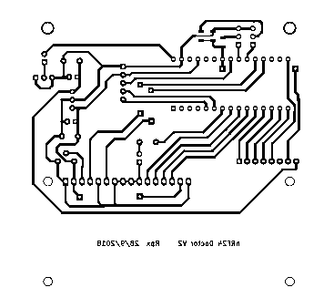
And a pcb, not so beautiful and compact than yours, but "Home made" 85x85mm single side with four straps.Anyway, I have one question, if the github nRF24DoctorGateway.ino compile correctly,
the nRF24DoctorNode.ino produce one error :/sketchbook/nRF24DoctorNode/nRF24DoctorNode.ino: In function 'void statemachine()':nRF24DoctorNode:566: error: 'RF24_getReceivedPowerDetector' was not declared in this scope
if (RF24_getReceivedPowerDetector())
^
If I comment this line, it compile correctly.What's wrong ?
Rpx
-
Done ! With your great help on github, I made one nRF24DoctorNode.
Some modifications : Battery powering with two LiIon from laptop, for 7.5 v on Arduino Nano Raw
The 1117 of Nano out 5.0v for Nano, LCD1602 and KY040 Rotary Encoder.
Finally the 5.0v powers a LE33 to produce 3.3v for nRF24.
Resistors smd, led and mosFETs (I try 40N03) are "second hand parts".
With your PDF schematics I redraw à nRF24DoctorNode with KiKad.
And a pcb, not so beautiful and compact than yours, but "Home made" 85x85mm single side with four straps.Anyway, I have one question, if the github nRF24DoctorGateway.ino compile correctly,
the nRF24DoctorNode.ino produce one error :/sketchbook/nRF24DoctorNode/nRF24DoctorNode.ino: In function 'void statemachine()':nRF24DoctorNode:566: error: 'RF24_getReceivedPowerDetector' was not declared in this scope
if (RF24_getReceivedPowerDetector())
^
If I comment this line, it compile correctly.What's wrong ?
Rpx
@rpx you need the development version of the mySensors library. 2.3.0 doesn't contain the functions for the received power detection graph yet.
The doctor will work with that line commented out, but the graph will stay empty.http://yveaux.blogspot.nl
-
@rpx you need the development version of the mySensors library. 2.3.0 doesn't contain the functions for the received power detection graph yet.
The doctor will work with that line commented out, but the graph will stay empty. -
@Yveaux
Thank you very much for your answer.
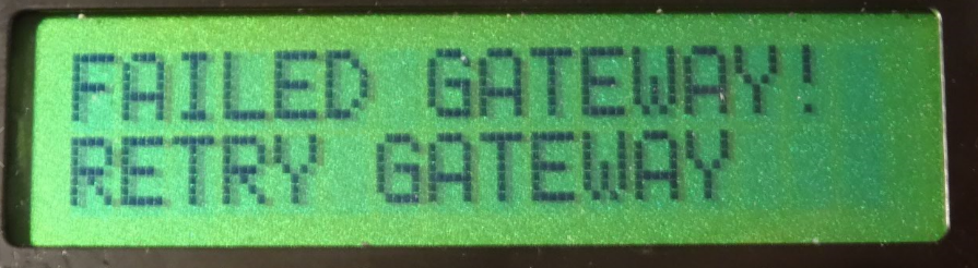
I upload nRF24DoctorNode.ino with commented line and ... It work's ! But it don't see any of my three gateways one serial and two Ethernet W5100 which are all on work.
First I have to build a fourth one with the nRF24DoctorGateway.ino sketch.
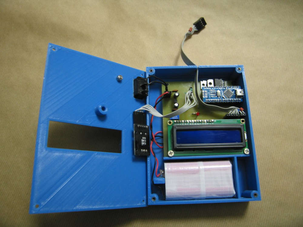
Some photos:
Front
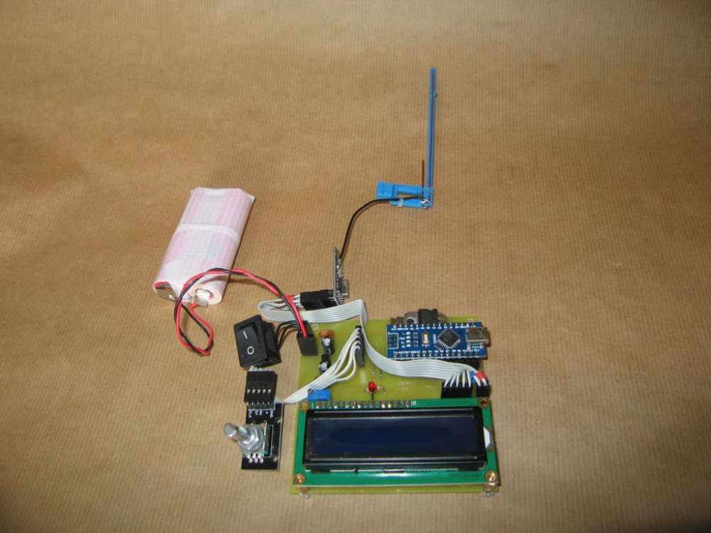
Front without Nano & LCD
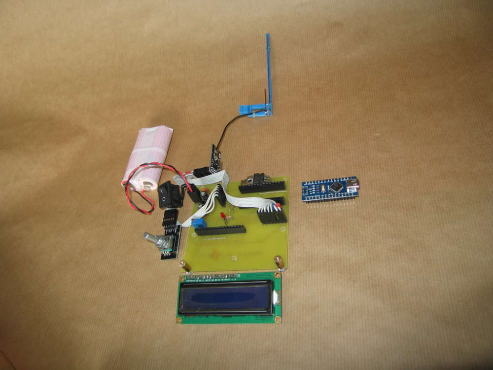
Back
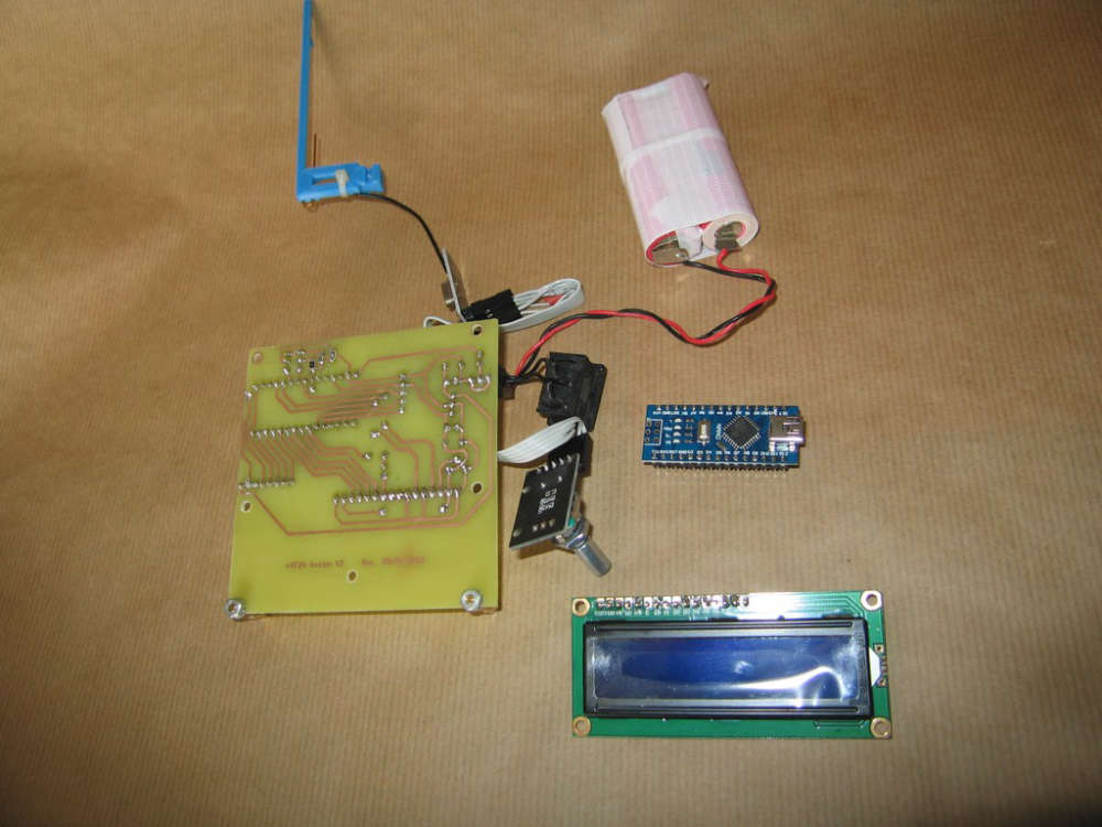
KiKad schematics: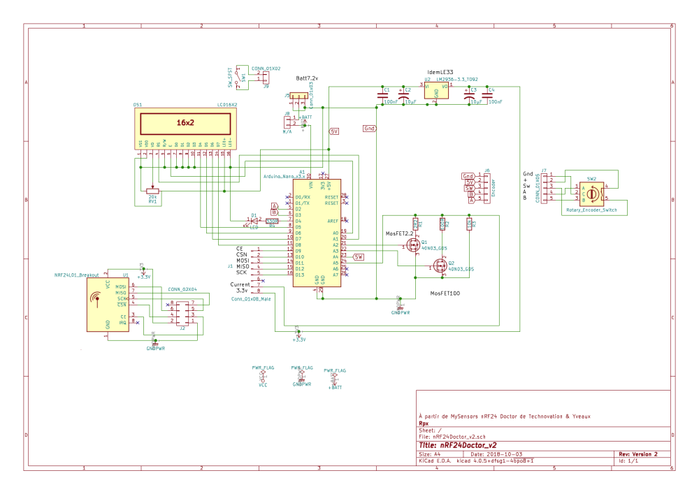
Pcb:
And LCD modifications:For D4 - D7 LCD #define LCD_D7 8 // 5 due to easier pcb design #define LCD_D6 7 // 6 #define LCD_D5 6 // 7 #define LCD_D4 5 // 8At last, I need to build an enclosure...
Rpx.
-
@rpx you need the development version of the mySensors library. 2.3.0 doesn't contain the functions for the received power detection graph yet.
The doctor will work with that line commented out, but the graph will stay empty. -
@yveaux Thanks !
One enclosure later...
I think about my three gateways weren't view.
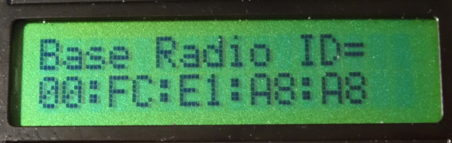
And made few adjustments.First in RadioConfig.h Ireplace "Zero CaFe BaBe" by my one of MY_RF24_BASE_RADIO_ID
/**
- @def MY_RF24_BASE_RADIO_ID
- @brief RF24 radio network identifier.
- This acts as base value for sensor nodeId addresses. Change this (or channel) if you have more
- than one sensor network.
*/
//0x00,0xCA,0xFE,0xBA,0xBE // modif Rpx de "Zero CaFe BaBe"
Second to be sure force selection of nRF24 CE on D9 and CS on D10
//PIN 9~13: NRF24 RADIO
#define MY_RF24_CE_PIN    (9)
#define MY_RF24_CS_PIN    (10)
And then Doctor is at work!
Enclosure Open
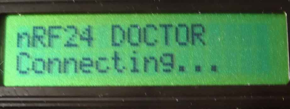
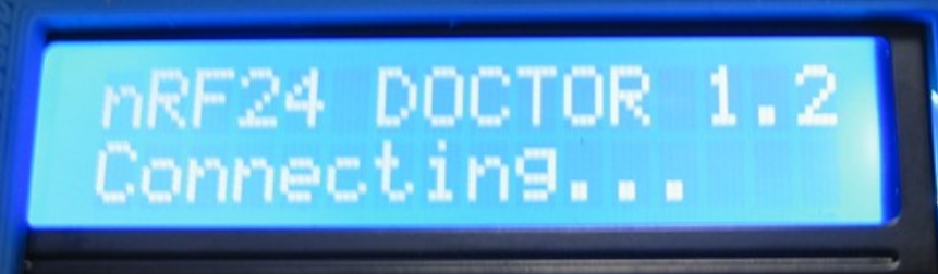
Connecting
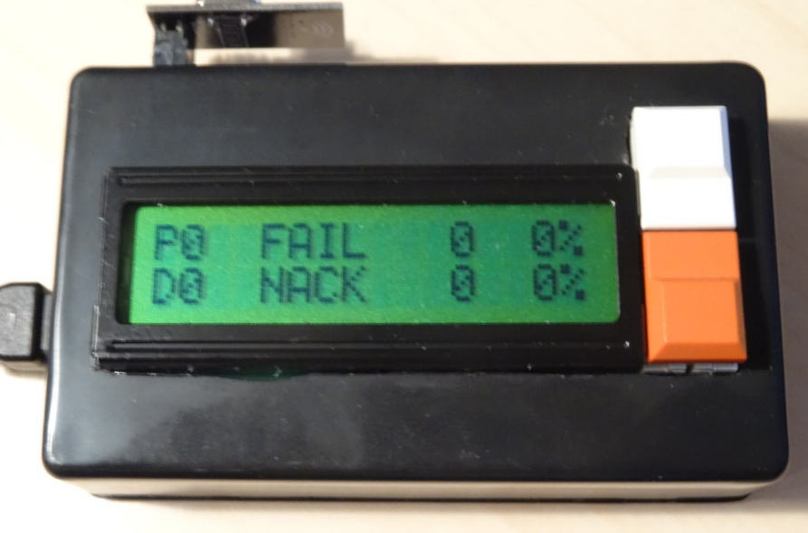
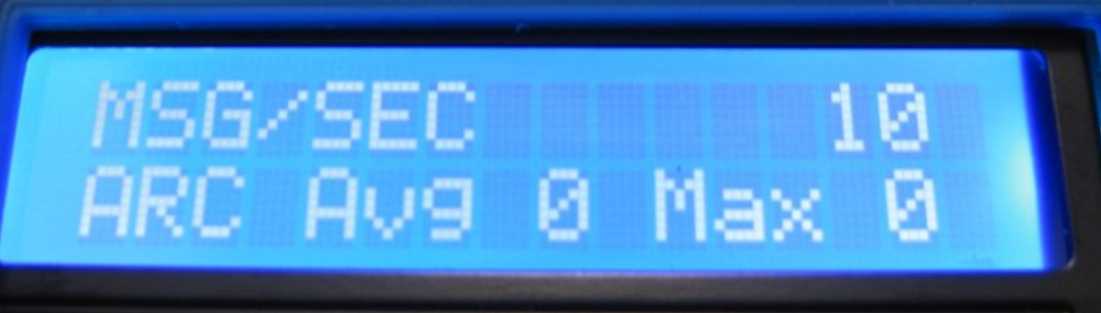
Msg
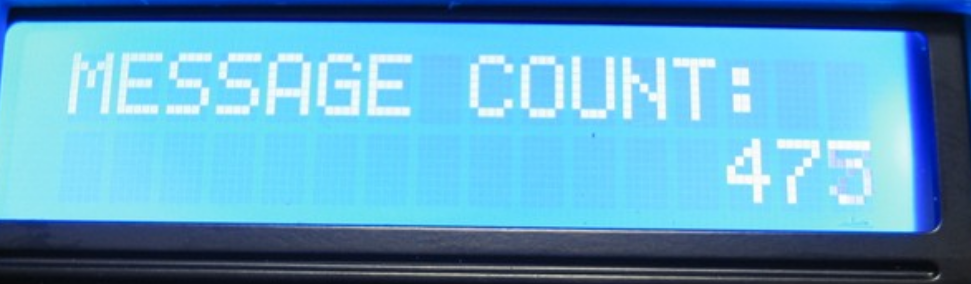
Message Count
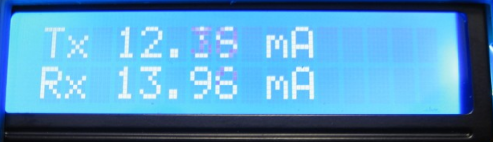
Tx Rx
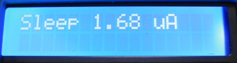
Sleep
Scan
At last, nRF24Doctor is working. Except scan due I think to use MySensors Library 2.2.0.
I don't know if a nRF24 PA LNA (20dBm) can be tested with nRF24Doctor but if my circuit design is used you should change LE33 witch output max 100mA because nRF24 PA LNA need 150mA min.
And one problem, a test with nRF24Doctor "freeze" Domoticz 3.8153, I need to stop service Domoticz and start to have a Domoticz web access.Thank you very much Yveaux.
Rpx. -
@yveaux Thanks !
One enclosure later...
I think about my three gateways weren't view.
And made few adjustments.First in RadioConfig.h Ireplace "Zero CaFe BaBe" by my one of MY_RF24_BASE_RADIO_ID
/**
- @def MY_RF24_BASE_RADIO_ID
- @brief RF24 radio network identifier.
- This acts as base value for sensor nodeId addresses. Change this (or channel) if you have more
- than one sensor network.
*/
//0x00,0xCA,0xFE,0xBA,0xBE // modif Rpx de "Zero CaFe BaBe"
Second to be sure force selection of nRF24 CE on D9 and CS on D10
//PIN 9~13: NRF24 RADIO
#define MY_RF24_CE_PIN    (9)
#define MY_RF24_CS_PIN    (10)
And then Doctor is at work!
Enclosure Open
Connecting
Msg
Message Count
Tx Rx
Sleep
Scan
At last, nRF24Doctor is working. Except scan due I think to use MySensors Library 2.2.0.
I don't know if a nRF24 PA LNA (20dBm) can be tested with nRF24Doctor but if my circuit design is used you should change LE33 witch output max 100mA because nRF24 PA LNA need 150mA min.
And one problem, a test with nRF24Doctor "freeze" Domoticz 3.8153, I need to stop service Domoticz and start to have a Domoticz web access.Thank you very much Yveaux.
Rpx.@rpx
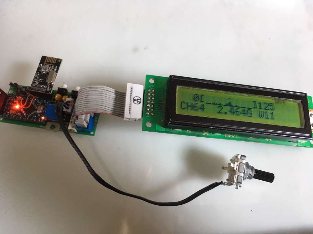
@Yveaux OK with a nRF24 gateway it's working fine. But, and I don't remember why, I need to strap pin 8 of nRF24L01+ (Irq) to Nano Pin D2, which is not required on mysensors gateways.
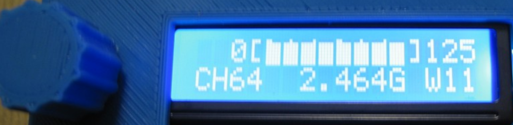
And with MySensors Library 2.3.0 beta Scan is working.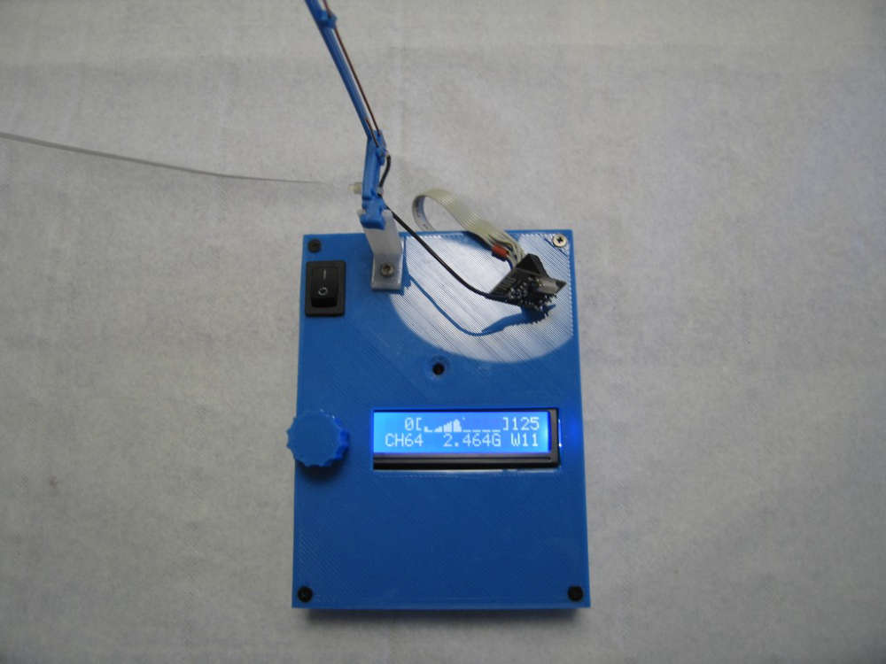
This pattern is a 950W microwave owen near by 0,60 meter.
The graph has 8 pixel high, can you give me a idea of the power scale of each pixel ?And I plan with friends help, to measure differents antennas in open field as J pole, Yagi-Uda and cloverleaf.
Rpx. -
@rpx
@Yveaux OK with a nRF24 gateway it's working fine. But, and I don't remember why, I need to strap pin 8 of nRF24L01+ (Irq) to Nano Pin D2, which is not required on mysensors gateways.
And with MySensors Library 2.3.0 beta Scan is working.
This pattern is a 950W microwave owen near by 0,60 meter.
The graph has 8 pixel high, can you give me a idea of the power scale of each pixel ?And I plan with friends help, to measure differents antennas in open field as J pole, Yagi-Uda and cloverleaf.
Rpx.@rpx said in nRF24Doctor:
The graph has 8 pixel high, can you give me a idea of the power scale of each pixel
Each time a carrier is detected on a channel the count for the channel is increased by 1, with a maximum of 255 per channel (per bucket really).
The top pixel of the chart gets set when the value is 128 or above, the next when 64 or above, then 32 etc. So kind of log2 logarithmic.
It makes the chart sensitive to small counts, but also displays larger values. -
@rpx said in nRF24Doctor:
The graph has 8 pixel high, can you give me a idea of the power scale of each pixel
Each time a carrier is detected on a channel the count for the channel is increased by 1, with a maximum of 255 per channel (per bucket really).
The top pixel of the chart gets set when the value is 128 or above, the next when 64 or above, then 32 etc. So kind of log2 logarithmic.
It makes the chart sensitive to small counts, but also displays larger values.This code is just great, Very good and impressive job.
While looking after recommendations for improving reliability of NRF24 links on easydomoticz french forum, @rpx put me through your NRFDoctor and I must admit is exceeds my expectations.
I just built it in few days and just starting to use it.
Tx/Rx statistic, Icc current measurements in sleep and operating modes, capabilities to reconfigure radio parameters between node and gateway, without forgeting the beautifull frequency range bar graph.
A perfect tool for Wifi and NRF links.
Many Thanks and regards
-
@rpx said in nRF24Doctor:
The graph has 8 pixel high, can you give me a idea of the power scale of each pixel
Each time a carrier is detected on a channel the count for the channel is increased by 1, with a maximum of 255 per channel (per bucket really).
The top pixel of the chart gets set when the value is 128 or above, the next when 64 or above, then 32 etc. So kind of log2 logarithmic.
It makes the chart sensitive to small counts, but also displays larger values. -
@benbidouille great to hear you like it!
Nice and compact build :+1:@Yveaux
Can you confirm your design is operating well with NRF24 radio modules with High Icc current consumption up to 150 mA like with PA modules ?I mean is clear Rds ON of MOSfet is chosen as low as possible, but the voltage drop across the 2.2ohm shunt might becomes critical especially along transcients when radio operates.
I added Caps at Radio Supply rails ends and also Jumper for shorting shunt circuitry in case of.
Again very nice and well engineered design.
I used 20x2 display instead of 16x2, How painfull would you think it is to extend the graph display resolution ?
-
@Yveaux
Can you confirm your design is operating well with NRF24 radio modules with High Icc current consumption up to 150 mA like with PA modules ?I mean is clear Rds ON of MOSfet is chosen as low as possible, but the voltage drop across the 2.2ohm shunt might becomes critical especially along transcients when radio operates.
I added Caps at Radio Supply rails ends and also Jumper for shorting shunt circuitry in case of.
Again very nice and well engineered design.
I used 20x2 display instead of 16x2, How painfull would you think it is to extend the graph display resolution ?
@benbidouille said in nRF24Doctor:
I used 20x2 display instead of 16x2, How painfull would you think it is to extend the graph display resolution ?
The number of columns of the LCD display can be changed here.
You manually would have to change the lengths of fixed strings, like starting from here.
Could very well be that you start running into memory issues then, as the AVR is pretty packed.Regarding current measurements; the design & calculations were done by @Technovation, maybe he can chip in.
I can remember we struggled with grounding issues, as different Nanos have different quality in grounding, leading to deviations in measured current. We ended up manually patching a Nano to improve the ground layout.
Hello! It looks like you're interested in this conversation, but you don't have an account yet.
Getting fed up of having to scroll through the same posts each visit? When you register for an account, you'll always come back to exactly where you were before, and choose to be notified of new replies (either via email, or push notification). You'll also be able to save bookmarks and upvote posts to show your appreciation to other community members.
With your input, this post could be even better 💗
Register Login