GUIDE - NRF5 / NRF51 / NRF52 for beginners
-
So you're curious about the NRF5 series boards huh? Let's dive in!
// updates can be found below.
WHAT IS THE NRF5
It's a tiny Arm processor based board that can work like an Arduino. There are a few flavours.
NRF51 $3
NRF52 $3
NRF52840 $20 (new, has built in usb support)Advantages:
- Arduino with built in NRF24 for just $3.
- The size of a postage stamp.
- Powerful enough to use the simple encryption functionality easily.
- Antenna socket: just plug in antenna for more range.
- Ultra low power use.
- You get to decide which pins do what. For example, you can decide through software which pins should be hardware serial pins. There's a small pin router built in.
- Built in support for NFC (swiping smart cards and tags).
Neutral:
- Has 3.3v internal logic. Most new sensors use 3.3v for logic too.
Negative:
- Relatively new, so there might still be some bugs in MySensors.
- The pins cannot handle as much current (5ma) as the Arduino's could (40ma).
- Smaller pin spacing (1.27mm instead of 2.54mm), so harder to solder. Fewer expansion boards available.
- Unlike the Arduino Nano, the programmer doesn't also function as a serial monitor. To get serial output you have to set some pins as the serial output, and then connect to those pins with a separate usb serial port adapter. It's a bit like the Arduino Pro Mini in that sense.
- The EByte module has no onboard LED, which makes it difficult to know it's on, or to test things with a simple blink sketch.
INSTALLATION
Open the Arduino software and install these two boards in the Arduino IDE:
https://github.com/sandeepmistry/arduino-nRF5
https://github.com/mysensors/ArduinoBoards
(click on the links to get installation instructions).Carefully soldered some wires to your board, and connected it a programming tool. The cheapest simplest option is to get an ST-Link v2 ($3).
Connect:
gnd ->gnd (in the corner)
3.3v -> vcc (in the same corner)
SWDIO -> SWDIO
SWDCLK -> SWDCLK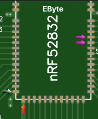
Software
In the Arduino IDE open an example (file -> examples -> myboardNRF5 -> myboardNRF5). You will now have three files:- Main file <- your main code goes here.
- MyBoardNRF5.h <- here you can set which goodies you want, on which pins.
- MyBoardNRF5.cpp <- probably no reason to change anything here.
In the main file make sure it has these lines:
#define MY_RADIO_NRF5_ESB
#include <MySensors.h>Upload settings
In the Arduino IDe click on the tools dropdown and start set things up like this:- Board: "MyBoardNRF5 NRF52832"
- Reset: "don't enable"
- Bootloader/SD: "none"
- Low frequency clock: "Crystal Oscilator" (RC Oscillator might work too).
- Port: none
- Programmer: ST-Link V2
First the chip you are using must be 'wiped'. This removes the bluetooth functionality. Wipe the chip by clicking "tools -> burn bootloader". You'll get an error but that's normal.
Next, when your sketch is complete, choose "sketch -> upload via programmer".
POWER HUNGRY SENSORS
If you were using an Arduino Nano before, then you might have powered your sensors directly from the Arduino's 5v pin. With these boards you can't run the power through the NRF5 board first. Make the 5V go 'around it'. Only use these boards to collect and send signals. To get a steady power supply, depending on how much you need, you could try:- An AMS1117 regulator. It can generate a max of 800ma at 3.3v. Here's a small version.
- Special power supply boards such as this one.
TROUBLESHOOTING
- Timed out while waiting for target halted: are your pins connected ok?
- Unable to reset target: are your pins connected ok?
ADVANCED KNOWLEDGE
- Some things, like turning on a pin when you press a button, can be handled by (programmed into) the 'periphery' of the chip. Not having to wake up the main chip saves some power. An example of this can be found here.
POPULAR BOARDS
Ebyte N73 - Manual
- Cheap: $3
- Is missing some parts that allows for super low power usage. Those can be added manually though.
- Forum users have created some nice pre-made prototyping boards, like this small one or this big one.
- Uses 91 milli amps max (while transmitting).
Fanstel BT832X
- Can't find the price
- Better range than the EByte
- Has the required 'DCDC' parts built in, allowing for super low battery usage.
- Uses 250ma max
Holyiot TinyBLE
- About $5
- Tiny! This also means it has less ports.
UPDATE
The easiest way to get started with NRF5 might actually be the BCC Microbit.
-
Hi.
I have read https://devzone.nordicsemi.com/b/blog/posts/measuring-lithium-battery-voltage-with-nrf51 but which pin is VBG? p0.01 = adc?
Need to recalclulate the resistance for 2 aaa batteries.
@alowhum Can you clearify how to read MyBoardNRF5.h? Is PIN_AIN0 = p0.00?
What is the benift to use hwPinMode instead of using pinMode()?
-
@alowhum ,
So, following these steps the radio will support nrf24 protocols and you could use, for example, one of the available RF24 libraries?@billgoolsby I don't know about other NRF24 libraries. But MySensors definitely works.
@smilvert: I am not an expert, I'm a beginner sharing what I learnt so far. Perhaps other experts on the forum can help. It's probably a good idea to post advanced questions in the NRF5 thread.
-
I am starting to experiment with NRF51822. Thank you all for this thread. I am stuck with setting up IDE on Win10 and my MCU is not communicating. What is the correct setup for Arduino IDE?
I have Port still grayed out and error: The selected port not exist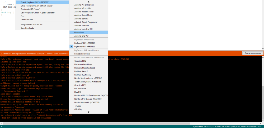
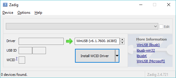
Could that be related to drivers? I've run Zadig, there are more options and I've tried all four of them
I am not able to upload even erase sketch. Any suggestion where to focus (IDE/Zadig/other)?
-
I am starting to experiment with NRF51822. Thank you all for this thread. I am stuck with setting up IDE on Win10 and my MCU is not communicating. What is the correct setup for Arduino IDE?
I have Port still grayed out and error: The selected port not existCould that be related to drivers? I've run Zadig, there are more options and I've tried all four of them
I am not able to upload even erase sketch. Any suggestion where to focus (IDE/Zadig/other)?
-
@xmonika have you tried to erase it? In most cases if is start with a new module I first need to erase is once.
Shortcut => burn bootloader, this will give an error but you should be good to go from there.
@omemanti @mfalkvidd Thank you, I think I did it. It works now - or I hope so from the code.
** Programming Finished **
** Verify Started **
nrf51.cpu: target state: halted
target halted due to breakpoint, current mode: Thread
xPSR: 0x61000000 pc: 0x2000002e msp: 0x20004000
verified 1412 bytes in 0.038633s (35.692 KiB/s)
** Verified OK **
** Resetting Target **
shutdown command invoked
What I was confused is that there is erase sketch, but to make it erased there is this trick with burn bootloader. Still the port is greyed out, but it seems I am able to flash blank sketch. Thanks
-
@xmonika I use the ST-Link, mine is always greyed out. The only time im able to select a port, it's when I'm using an FTDI to use the serial monitor. So I think everything looks normal.
I have tried EVERYTHING to get an ST-LINK V2 to program an NRF52. That includes - multiple ST-LINK's, multiple computers, Linux, "burn bootloader" first, and pretty much everything I could read on this forum. The error message is always:
Open On-Chip Debugger 0.10.0-dev-00254-g696fc0a (2016-04-10-10:13)
Licensed under GNU GPL v2
For bug reports, read
http://openocd.org/doc/doxygen/bugs.html
debug_level: 2
0x4000
Info : The selected transport took over low-level target control. The results might differ compared to plain JTAG/SWD
adapter speed: 10000 kHz
Info : Unable to match requested speed 10000 kHz, using 4000 kHz
Info : Unable to match requested speed 10000 kHz, using 4000 kHz
Info : clock speed 4000 kHz
Info : STLINK v2 JTAG v32 API v2 SWIM v7 VID 0x0483 PID 0x3748
Info : using stlink api v2
Info : Target voltage: 3.252590
An error occurred while uploading the sketch
Error: init mode failed (unable to connect to the target)
in procedure 'program'
in procedure 'init' called at file "embedded:startup.tcl", line 473
in procedure 'ocd_bouncer'
** OpenOCD init failed **
shutdown command invokedAny ideas?
Thanks!
-
Are you powering the target from an external power source? If not, try that.
-
Unfortunately- I did try that - although without an led it’s hard to know if the board really is getting power. I will check with a multimeter.
@ileneken3 said in GUIDE - NRF5 / NRF51 / NRF52 for beginners:
hat - although without an led it’s hard to know if the board really is getting power. I will check with a multimeter.
did you use zadig to install the drivers for the ST-Link?
-
@ileneken3 said in GUIDE - NRF5 / NRF51 / NRF52 for beginners:
hat - although without an led it’s hard to know if the board really is getting power. I will check with a multimeter.
did you use zadig to install the drivers for the ST-Link?
-
Unfortunately- I did try that - although without an led it’s hard to know if the board really is getting power. I will check with a multimeter.
-
Yes, I used Zadig. From the Device Manager in Windows, it displays "STM32 STLink" when the programmer is plugged in.
In Linux, the device seems to be recognized automatically without installing any drivers. -
Yes, I'm connecting 3.3 volts to VCC and GND on the board, while connecting the programmer to the PC's USB port. I'm assuming there is no need for a common ground?
Oh well...
@ileneken3
After giving up on the cheap (illegal?) ST-LINK and J-LINK boards, I decided to make my life easy and get a NRF-DK. Unfortunately, even that is not easy enough . I did manage to use nRFgo Studio to flash a pre-built .hex file (blinky_pca10040.hex) to the EBYTE E73 module. I know it works because I attached an LED to a pin on the module and I see it blinks. But I can't do what I really want - flash a simple Mysensors sketch (preferably with the Arduino IDE).
Everything compiles OK, I'm using the very latest MyBoardNRF5 board definition (including the Sandeep Mistry libraries). But the Arduino IDE won't recognize the J-LINK programmer that is built into the DK board. (Maybe that's not expected to work?)As a workaround, from the Arduino IDE, I select "Export compiled Binary", and then use the resultant .hex file with nRFgo Studio to flash the board. Everything seems fine, but I get no indication from the gateway that any wireless traffic is received from the board - so I assume it is not working at all. Below is the sketch.
#define MY_RADIO_NRF5_ESB
#define MY_DEBUG
#define MY_NODE_ID 10 // 0x0a nrf test
#define CHILD_ID 55  // Id of the sensor child

#include <SPI.h>
#include <MySensors.h>


// Initialize motion message
MyMessage msg(CHILD_ID, V_TRIPPED);


bool value = 1;
void setup() {
  Serial.println("I am starting");

    send(msg.set(value)); // Get things started

  // initialize digital pin LED_BUILTIN as an output.
  //pinMode(13, OUTPUT);
}

void presentation()  {

  sendSketchInfo("NRF52", "0.9");

  present(CHILD_ID, S_MOTION);
}
void loop() {
  Serial.println("I am in a loop");
  //digitalWrite(13, HIGH);   // turn the LED on (HIGH is the voltage level)
  //delay(3000);                       // wait for a second
  //digitalWrite(LED_BUILTIN, LOW);
  delay(3000);                       // wait for a second

}
P.S.
I have not managed to get any console output using the TX/RX pins to work either.
It would really brighten up my holidays if someone could point me in the right direction!Thanks,
-
@ileneken3
After giving up on the cheap (illegal?) ST-LINK and J-LINK boards, I decided to make my life easy and get a NRF-DK. Unfortunately, even that is not easy enough . I did manage to use nRFgo Studio to flash a pre-built .hex file (blinky_pca10040.hex) to the EBYTE E73 module. I know it works because I attached an LED to a pin on the module and I see it blinks. But I can't do what I really want - flash a simple Mysensors sketch (preferably with the Arduino IDE).
Everything compiles OK, I'm using the very latest MyBoardNRF5 board definition (including the Sandeep Mistry libraries). But the Arduino IDE won't recognize the J-LINK programmer that is built into the DK board. (Maybe that's not expected to work?)As a workaround, from the Arduino IDE, I select "Export compiled Binary", and then use the resultant .hex file with nRFgo Studio to flash the board. Everything seems fine, but I get no indication from the gateway that any wireless traffic is received from the board - so I assume it is not working at all. Below is the sketch.
#define MY_RADIO_NRF5_ESB
#define MY_DEBUG
#define MY_NODE_ID 10 // 0x0a nrf test
#define CHILD_ID 55  // Id of the sensor child

#include <SPI.h>
#include <MySensors.h>


// Initialize motion message
MyMessage msg(CHILD_ID, V_TRIPPED);


bool value = 1;
void setup() {
  Serial.println("I am starting");

    send(msg.set(value)); // Get things started

  // initialize digital pin LED_BUILTIN as an output.
  //pinMode(13, OUTPUT);
}

void presentation()  {

  sendSketchInfo("NRF52", "0.9");

  present(CHILD_ID, S_MOTION);
}
void loop() {
  Serial.println("I am in a loop");
  //digitalWrite(13, HIGH);   // turn the LED on (HIGH is the voltage level)
  //delay(3000);                       // wait for a second
  //digitalWrite(LED_BUILTIN, LOW);
  delay(3000);                       // wait for a second

}
P.S.
I have not managed to get any console output using the TX/RX pins to work either.
It would really brighten up my holidays if someone could point me in the right direction!Thanks,
@ileneken3 1. how did you wire the DK tot the target module?
https://forum.mysensors.org/topic/6961/nrf5-action/1744
- What is the error the Arduino IDE produces?
- Can you also post the myboardnrf(sounds like..) files?
FYI, I both use the stlink and nrf52832-DK for programming. And I'm pretty sure the stlink I use is not so original. 2 dollar each.
-
@ileneken3 1. how did you wire the DK tot the target module?
https://forum.mysensors.org/topic/6961/nrf5-action/1744
- What is the error the Arduino IDE produces?
- Can you also post the myboardnrf(sounds like..) files?
FYI, I both use the stlink and nrf52832-DK for programming. And I'm pretty sure the stlink I use is not so original. 2 dollar each.
- I wired the DK to the target exactly as described in the article, and as drawn in the picture:
https://devzone.nordicsemi.com/f/nordic-q-a/20536/programming-external-custom-nrf52832-board-using-nrf52-dk
I am assuming everything is correct in the wiring, because I was able to flash the blinky pre-compiled hex file and it works. - When selecting J-Link as the programmer, the error from the Arduino IDE is:
C:\Users\krakman\AppData\Local\Arduino15\packages\sandeepmistry\tools\openocd\0.10.0-dev.nrf5/bin/openocd.exe -d2 -f interface/jlink.cfg -c transport select swd; set WORKAREASIZE 0; -f target/nrf52.cfg -c program {{C:\Users\krakman\AppData\Local\Temp\arduino_build_268238/MyBoardNRF5tst.ino.hex}} verify reset; shutdown;
Open On-Chip Debugger 0.10.0-dev-00254-g696fc0a (2016-04-10-10:13)
Licensed under GNU GPL v2
For bug reports, read
http://openocd.org/doc/doxygen/bugs.html
debug_level: 2
0
adapter speed: 10000 kHz
cortex_m reset_config sysresetreq
jaylink: Failed to open device: LIBUSB_ERROR_NOT_FOUND.
Info : No device selected, using first device.
Error: No J-Link device found.
Error: No Valid JTAG Interface Configured.
Error: No Valid JTAG Interface Configured./* If you don't use an nRF5 board, you can ignore this file. This file was part of the "My Sensors nRF5 Boards" board repository available at https://github.com/mysensors/ArduinoBoards If you have questions, please refer the documentation at https://github.com/mysensors/ArduinoHwNRF5 first. This file is compatible with ArduinoHwNRF5 >= 0.2.0 This file allows you to change the relation between pins referenced in the Arduino IDE (0..31) and pins of the nRF5 MCU (P0.00..P0.31). If you can live with addressing the GPIO pins by using the Arduino pins 0..31 instead of a custom mapping, don't change this file. If you have a lot of Arduino code with fixed pin numbers and you need to map these pins to specific pins of the nRF5 MCU; you need to change this file. If you fill the "g_APinDescription" Array with numbers between 0..31, the Arduino pins 0..31 are assigned to pins P0.00..P0.31 of the MCU. As an example, if you need to change the pin mapping for Arduino pin 5 to P0.12 of the MCU, you have to write the 12 after PORT0 into the sixth position in the "g_APinDescription" Array. The extended attributes only affects the nRF5 variants provided with official Arduino boards. The arduino-nrf5 variant ignores the extended attributes. The pin mapping effects commands like "pinMode()", "digitalWrite()", "analogRead()" and "analogWrite()". If you change the pin mapping, you have to modify the pins in "MyBoardNRF5.h". Especially the analog pin mapping must be replaced with your pin numbers by replacing PIN_AIN0..7 with a number of your mapping array. You can use the constants PIN_AIN0..7 in the "g_APinDescription" Array if you want to reference analog ports MCU independent. You cannot use the pins P0.00 and P0.01 for GPIO, when the 32kHz crystal is connected. ########################################################################### Copyright (c) 2014-2015 Arduino LLC. All right reserved. Copyright (c) 2016 Arduino Srl. All right reserved. Copyright (c) 2017 Sensnology AB. All right reserved. This library is free software; you can redistribute it and/or modify it under the terms of the GNU Lesser General Public License as published by the Free Software Foundation; either version 2.1 of the License, or (at your option) any later version. This library is distributed in the hope that it will be useful, but WITHOUT ANY WARRANTY; without even the implied warranty of MERCHANTABILITY or FITNESS FOR A PARTICULAR PURPOSE. See the GNU Lesser General Public License for more details. You should have received a copy of the GNU Lesser General Public License along with this library; if not, write to the Free Software Foundation, Inc., 51 Franklin St, Fifth Floor, Boston, MA 02110-1301 USA */ #ifdef MYBOARDNRF5 #include <variant.h> /* * Pins descriptions. Attributes are ignored by arduino-nrf5 variant. * Definition taken from Arduino Primo Core with ordered ports */ const PinDescription g_APinDescription[]= { { NOT_A_PORT, 0, PIO_DIGITAL, PIN_ATTR_DIGITAL, No_ADC_Channel, NOT_ON_PWM, NOT_ON_TIMER}, // LFCLK { NOT_A_PORT, 1, PIO_DIGITAL, PIN_ATTR_DIGITAL, No_ADC_Channel, NOT_ON_PWM, NOT_ON_TIMER}, // LFCLK { PORT0, 2, PIO_DIGITAL, (PIN_ATTR_DIGITAL|PIN_ATTR_PWM), ADC_A0, PWM4, NOT_ON_TIMER}, { PORT0, 3, PIO_DIGITAL, (PIN_ATTR_DIGITAL|PIN_ATTR_PWM), ADC_A1, PWM5, NOT_ON_TIMER}, { PORT0, 4, PIO_DIGITAL, (PIN_ATTR_DIGITAL|PIN_ATTR_PWM), ADC_A2, PWM6, NOT_ON_TIMER}, { PORT0, 5, PIO_DIGITAL, (PIN_ATTR_DIGITAL|PIN_ATTR_PWM), ADC_A3, PWM7, NOT_ON_TIMER}, { PORT0, 6, PIO_DIGITAL, PIN_ATTR_DIGITAL, No_ADC_Channel, NOT_ON_PWM, NOT_ON_TIMER}, // INT3 { PORT0, 7, PIO_DIGITAL, PIN_ATTR_DIGITAL, No_ADC_Channel, NOT_ON_PWM, NOT_ON_TIMER}, // INT4 { PORT0, 8, PIO_DIGITAL, (PIN_ATTR_DIGITAL|PIN_ATTR_PWM), No_ADC_Channel, PWM10, NOT_ON_TIMER}, //USER_LED { PORT0, 9, PIO_DIGITAL, PIN_ATTR_DIGITAL, No_ADC_Channel, NOT_ON_PWM, NOT_ON_TIMER}, // NFC1 { PORT0, 10, PIO_DIGITAL, PIN_ATTR_DIGITAL, No_ADC_Channel, NOT_ON_PWM, NOT_ON_TIMER}, // NFC2 { PORT0, 11, PIO_DIGITAL, PIN_ATTR_DIGITAL, No_ADC_Channel, NOT_ON_PWM, NOT_ON_TIMER}, // TX { PORT0, 12, PIO_DIGITAL, PIN_ATTR_DIGITAL, No_ADC_Channel, NOT_ON_PWM, NOT_ON_TIMER}, // RX { PORT0, 13, PIO_DIGITAL, PIN_ATTR_DIGITAL, No_ADC_Channel, NOT_ON_PWM, NOT_ON_TIMER}, // SDA { PORT0, 14, PIO_DIGITAL, PIN_ATTR_DIGITAL, No_ADC_Channel, NOT_ON_PWM, NOT_ON_TIMER}, // SCL { PORT0, 15, PIO_DIGITAL, PIN_ATTR_DIGITAL, No_ADC_Channel, NOT_ON_PWM, NOT_ON_TIMER}, // SDA1 { PORT0, 16, PIO_DIGITAL, PIN_ATTR_DIGITAL, No_ADC_Channel, NOT_ON_PWM, NOT_ON_TIMER}, // SCL1 { PORT0, 17, PIO_DIGITAL, PIN_ATTR_DIGITAL, No_ADC_Channel, NOT_ON_PWM, NOT_ON_TIMER}, // TP4 { PORT0, 18, PIO_DIGITAL, PIN_ATTR_DIGITAL, No_ADC_Channel, NOT_ON_PWM, NOT_ON_TIMER}, // TP5 { PORT0, 19, PIO_DIGITAL, PIN_ATTR_DIGITAL, No_ADC_Channel, NOT_ON_PWM, NOT_ON_TIMER}, // INT2 { PORT0, 20, PIO_DIGITAL, PIN_ATTR_DIGITAL, No_ADC_Channel, NOT_ON_PWM, NOT_ON_TIMER}, // INT1 { PORT0, 21, PIO_DIGITAL, PIN_ATTR_DIGITAL, No_ADC_Channel, NOT_ON_PWM, NOT_ON_TIMER}, // INT1 { PORT0, 22, PIO_DIGITAL, (PIN_ATTR_DIGITAL|PIN_ATTR_PWM), No_ADC_Channel, PWM9, NOT_ON_TIMER}, { PORT0, 23, PIO_DIGITAL, (PIN_ATTR_DIGITAL|PIN_ATTR_PWM), No_ADC_Channel, PWM8, NOT_ON_TIMER}, { PORT0, 24, PIO_DIGITAL, PIN_ATTR_DIGITAL, No_ADC_Channel, NOT_ON_PWM, NOT_ON_TIMER}, // INT { PORT0, 25, PIO_DIGITAL, (PIN_ATTR_DIGITAL|PIN_ATTR_PWM), No_ADC_Channel, PWM11, NOT_ON_TIMER}, //RED_LED { PORT0, 26, PIO_DIGITAL, (PIN_ATTR_DIGITAL|PIN_ATTR_PWM), No_ADC_Channel, PWM11, NOT_ON_TIMER}, //GREEN_LED { PORT0, 27, PIO_DIGITAL, (PIN_ATTR_DIGITAL|PIN_ATTR_PWM), No_ADC_Channel, PWM11, NOT_ON_TIMER}, //BLUE_LED { PORT0, 28, PIO_DIGITAL, (PIN_ATTR_DIGITAL|PIN_ATTR_PWM), ADC_A4, PWM3, NOT_ON_TIMER}, { PORT0, 29, PIO_DIGITAL, (PIN_ATTR_DIGITAL|PIN_ATTR_PWM), ADC_A5, PWM2, NOT_ON_TIMER}, { PORT0, 30, PIO_DIGITAL, (PIN_ATTR_DIGITAL|PIN_ATTR_PWM), ADC_A6, PWM1, NOT_ON_TIMER}, { PORT0, 31, PIO_DIGITAL, (PIN_ATTR_DIGITAL|PIN_ATTR_PWM), ADC_A7, PWM0, NOT_ON_TIMER} }; // Don't remove this line #include <compat_pin_mapping.h> #endif/* If you don't use an nRF5 board, you can ignore this file. This file was part of the "My Sensors nRF5 Boards" board repository available at https://github.com/mysensors/ArduinoBoards If you have questions, please refer the documentation at https://github.com/mysensors/ArduinoHwNRF5 first. This file is compatible with ArduinoHwNRF5 >= 0.2.0 This file allows you to change the pins of internal hardware, like the serial port, SPI bus or Wire bus. All pins referenced here are mapped via the "g_ADigitalPinMap" Array defined in "MyBoardNRF5.cpp" to pins of the MCU. As an example, if you have at the third position in "g_ADigitalPinMap" the 12, then all ports referenced in Arduino with 2 are mapped to P0.12. If you don't change the "g_ADigitalPinMap" Array, the Arduino pins 0..31 are translated to P0.00..P0..31. ########################################################################### This file is compatible with ArduinoHwNRF5 > 0.1.0 Copyright (c) 2014-2015 Arduino LLC. All right reserved. Copyright (c) 2016 Sandeep Mistry. All right reserved. Copyright (c) 2017 Sensnology AB. All right reserved. This library is free software; you can redistribute it and/or modify it under the terms of the GNU Lesser General Public License as published by the Free Software Foundation; either version 2.1 of the License, or (at your option) any later version. This library is distributed in the hope that it will be useful, but WITHOUT ANY WARRANTY; without even the implied warranty of MERCHANTABILITY or FITNESS FOR A PARTICULAR PURPOSE. See the GNU Lesser General Public License for more details. You should have received a copy of the GNU Lesser General Public License along with this library; if not, write to the Free Software Foundation, Inc., 51 Franklin St, Fifth Floor, Boston, MA 02110-1301 USA */ #ifndef _MYBOARDNRF5_H_ #define _MYBOARDNRF5_H_ #ifdef __cplusplus extern "C" { #endif // __cplusplus // Number of pins defined in PinDescription array #define PINS_COUNT (32u) #define NUM_DIGITAL_PINS (32u) #define NUM_ANALOG_INPUTS (8u) #define NUM_ANALOG_OUTPUTS (8u) /* * LEDs * * This is optional * * With My Sensors, you can use * hwPinMode() instead of pinMode() * hwPinMode() allows to use advanced modes like OUTPUT_H0H1 to drive LEDs. * https://github.com/mysensors/MySensors/blob/development/drivers/NRF5/nrf5_wiring_constants.h * */ #define PIN_LED1 (8) // #define PIN_LED2 (25) // #define PIN_LED3 (26) // #define PIN_LED4 (27) // #define PIN_LED5 (12) // #define PIN_LED6 (14) // #define PIN_LED7 (15) // #define PIN_LED8 (16) // #define USER_LED (PIN_LED2) // #define RED_LED (PIN_LED3) // #define GREEN_LED (PIN_LED4) // #define BLUE_LED (PIN_LED1) // #define BLE_LED BLUE_LED #define LED_BUILTIN PIN_LED1 /* * Buttons * * This is optional */ // #define PIN_BUTTON1 (3) // #define PIN_BUTTON2 (4) // #define PIN_BUTTON3 (5) // #define PIN_BUTTON4 (6) // #define PIN_BUTTON5 (7) // #define PIN_BUTTON6 (8) // #define PIN_BUTTON7 (9) // #define PIN_BUTTON8 (10) /* * Analog ports * * If you change g_APinDescription, replace PIN_AIN0 with * port numbers mapped by the g_APinDescription Array. * You can add PIN_AIN0 to the g_APinDescription Array if * you want provide analog ports MCU independed, you can add * PIN_AIN0..PIN_AIN7 to your custom g_APinDescription Array * defined in MyBoardNRF5.cpp */ static const uint8_t A0 = ADC_A0; static const uint8_t A1 = ADC_A1; static const uint8_t A2 = ADC_A2; static const uint8_t A3 = ADC_A3; static const uint8_t A4 = ADC_A4; static const uint8_t A5 = ADC_A5; static const uint8_t A6 = ADC_A6; static const uint8_t A7 = ADC_A7; /* * Serial interfaces * * RX and TX are required. * If you have no serial port, use unused pins * CTS and RTS are optional. */ /* #define PIN_SERIAL_RX (12) #define PIN_SERIAL_TX (11) */ // I changed this.... #define PIN_SERIAL_RX (13) #define PIN_SERIAL_TX (14) // #define PIN_SERIAL_CTS (13) // #define PIN_SERIAL_RTS (14) /* * SPI Interfaces * * This is optional * * If SPI is defined MISO, MOSI, SCK are required * SS is optional and can be used in your sketch. */ #define SPI_INTERFACES_COUNT 1 #define PIN_SPI_MISO (2) #define PIN_SPI_MOSI (3) #define PIN_SPI_SCK (4) #define PIN_SPI_SS (5) static const uint8_t SS = PIN_SPI_SS; static const uint8_t MOSI = PIN_SPI_MOSI; static const uint8_t MISO = PIN_SPI_MISO; static const uint8_t SCK = PIN_SPI_SCK; /* * Wire Interfaces * * This is optional */ #define WIRE_INTERFACES_COUNT 2 #define PIN_WIRE_SDA (13u) #define PIN_WIRE_SCL (14u) #define PIN_WIRE_SDA1 (15u) #define PIN_WIRE_SCL1 (16u) static const uint8_t SDA = PIN_WIRE_SDA; static const uint8_t SCL = PIN_WIRE_SCL; #ifdef __cplusplus } #endif #endif -
- I wired the DK to the target exactly as described in the article, and as drawn in the picture:
https://devzone.nordicsemi.com/f/nordic-q-a/20536/programming-external-custom-nrf52832-board-using-nrf52-dk
I am assuming everything is correct in the wiring, because I was able to flash the blinky pre-compiled hex file and it works. - When selecting J-Link as the programmer, the error from the Arduino IDE is:
C:\Users\krakman\AppData\Local\Arduino15\packages\sandeepmistry\tools\openocd\0.10.0-dev.nrf5/bin/openocd.exe -d2 -f interface/jlink.cfg -c transport select swd; set WORKAREASIZE 0; -f target/nrf52.cfg -c program {{C:\Users\krakman\AppData\Local\Temp\arduino_build_268238/MyBoardNRF5tst.ino.hex}} verify reset; shutdown;
Open On-Chip Debugger 0.10.0-dev-00254-g696fc0a (2016-04-10-10:13)
Licensed under GNU GPL v2
For bug reports, read
http://openocd.org/doc/doxygen/bugs.html
debug_level: 2
0
adapter speed: 10000 kHz
cortex_m reset_config sysresetreq
jaylink: Failed to open device: LIBUSB_ERROR_NOT_FOUND.
Info : No device selected, using first device.
Error: No J-Link device found.
Error: No Valid JTAG Interface Configured.
Error: No Valid JTAG Interface Configured./* If you don't use an nRF5 board, you can ignore this file. This file was part of the "My Sensors nRF5 Boards" board repository available at https://github.com/mysensors/ArduinoBoards If you have questions, please refer the documentation at https://github.com/mysensors/ArduinoHwNRF5 first. This file is compatible with ArduinoHwNRF5 >= 0.2.0 This file allows you to change the relation between pins referenced in the Arduino IDE (0..31) and pins of the nRF5 MCU (P0.00..P0.31). If you can live with addressing the GPIO pins by using the Arduino pins 0..31 instead of a custom mapping, don't change this file. If you have a lot of Arduino code with fixed pin numbers and you need to map these pins to specific pins of the nRF5 MCU; you need to change this file. If you fill the "g_APinDescription" Array with numbers between 0..31, the Arduino pins 0..31 are assigned to pins P0.00..P0.31 of the MCU. As an example, if you need to change the pin mapping for Arduino pin 5 to P0.12 of the MCU, you have to write the 12 after PORT0 into the sixth position in the "g_APinDescription" Array. The extended attributes only affects the nRF5 variants provided with official Arduino boards. The arduino-nrf5 variant ignores the extended attributes. The pin mapping effects commands like "pinMode()", "digitalWrite()", "analogRead()" and "analogWrite()". If you change the pin mapping, you have to modify the pins in "MyBoardNRF5.h". Especially the analog pin mapping must be replaced with your pin numbers by replacing PIN_AIN0..7 with a number of your mapping array. You can use the constants PIN_AIN0..7 in the "g_APinDescription" Array if you want to reference analog ports MCU independent. You cannot use the pins P0.00 and P0.01 for GPIO, when the 32kHz crystal is connected. ########################################################################### Copyright (c) 2014-2015 Arduino LLC. All right reserved. Copyright (c) 2016 Arduino Srl. All right reserved. Copyright (c) 2017 Sensnology AB. All right reserved. This library is free software; you can redistribute it and/or modify it under the terms of the GNU Lesser General Public License as published by the Free Software Foundation; either version 2.1 of the License, or (at your option) any later version. This library is distributed in the hope that it will be useful, but WITHOUT ANY WARRANTY; without even the implied warranty of MERCHANTABILITY or FITNESS FOR A PARTICULAR PURPOSE. See the GNU Lesser General Public License for more details. You should have received a copy of the GNU Lesser General Public License along with this library; if not, write to the Free Software Foundation, Inc., 51 Franklin St, Fifth Floor, Boston, MA 02110-1301 USA */ #ifdef MYBOARDNRF5 #include <variant.h> /* * Pins descriptions. Attributes are ignored by arduino-nrf5 variant. * Definition taken from Arduino Primo Core with ordered ports */ const PinDescription g_APinDescription[]= { { NOT_A_PORT, 0, PIO_DIGITAL, PIN_ATTR_DIGITAL, No_ADC_Channel, NOT_ON_PWM, NOT_ON_TIMER}, // LFCLK { NOT_A_PORT, 1, PIO_DIGITAL, PIN_ATTR_DIGITAL, No_ADC_Channel, NOT_ON_PWM, NOT_ON_TIMER}, // LFCLK { PORT0, 2, PIO_DIGITAL, (PIN_ATTR_DIGITAL|PIN_ATTR_PWM), ADC_A0, PWM4, NOT_ON_TIMER}, { PORT0, 3, PIO_DIGITAL, (PIN_ATTR_DIGITAL|PIN_ATTR_PWM), ADC_A1, PWM5, NOT_ON_TIMER}, { PORT0, 4, PIO_DIGITAL, (PIN_ATTR_DIGITAL|PIN_ATTR_PWM), ADC_A2, PWM6, NOT_ON_TIMER}, { PORT0, 5, PIO_DIGITAL, (PIN_ATTR_DIGITAL|PIN_ATTR_PWM), ADC_A3, PWM7, NOT_ON_TIMER}, { PORT0, 6, PIO_DIGITAL, PIN_ATTR_DIGITAL, No_ADC_Channel, NOT_ON_PWM, NOT_ON_TIMER}, // INT3 { PORT0, 7, PIO_DIGITAL, PIN_ATTR_DIGITAL, No_ADC_Channel, NOT_ON_PWM, NOT_ON_TIMER}, // INT4 { PORT0, 8, PIO_DIGITAL, (PIN_ATTR_DIGITAL|PIN_ATTR_PWM), No_ADC_Channel, PWM10, NOT_ON_TIMER}, //USER_LED { PORT0, 9, PIO_DIGITAL, PIN_ATTR_DIGITAL, No_ADC_Channel, NOT_ON_PWM, NOT_ON_TIMER}, // NFC1 { PORT0, 10, PIO_DIGITAL, PIN_ATTR_DIGITAL, No_ADC_Channel, NOT_ON_PWM, NOT_ON_TIMER}, // NFC2 { PORT0, 11, PIO_DIGITAL, PIN_ATTR_DIGITAL, No_ADC_Channel, NOT_ON_PWM, NOT_ON_TIMER}, // TX { PORT0, 12, PIO_DIGITAL, PIN_ATTR_DIGITAL, No_ADC_Channel, NOT_ON_PWM, NOT_ON_TIMER}, // RX { PORT0, 13, PIO_DIGITAL, PIN_ATTR_DIGITAL, No_ADC_Channel, NOT_ON_PWM, NOT_ON_TIMER}, // SDA { PORT0, 14, PIO_DIGITAL, PIN_ATTR_DIGITAL, No_ADC_Channel, NOT_ON_PWM, NOT_ON_TIMER}, // SCL { PORT0, 15, PIO_DIGITAL, PIN_ATTR_DIGITAL, No_ADC_Channel, NOT_ON_PWM, NOT_ON_TIMER}, // SDA1 { PORT0, 16, PIO_DIGITAL, PIN_ATTR_DIGITAL, No_ADC_Channel, NOT_ON_PWM, NOT_ON_TIMER}, // SCL1 { PORT0, 17, PIO_DIGITAL, PIN_ATTR_DIGITAL, No_ADC_Channel, NOT_ON_PWM, NOT_ON_TIMER}, // TP4 { PORT0, 18, PIO_DIGITAL, PIN_ATTR_DIGITAL, No_ADC_Channel, NOT_ON_PWM, NOT_ON_TIMER}, // TP5 { PORT0, 19, PIO_DIGITAL, PIN_ATTR_DIGITAL, No_ADC_Channel, NOT_ON_PWM, NOT_ON_TIMER}, // INT2 { PORT0, 20, PIO_DIGITAL, PIN_ATTR_DIGITAL, No_ADC_Channel, NOT_ON_PWM, NOT_ON_TIMER}, // INT1 { PORT0, 21, PIO_DIGITAL, PIN_ATTR_DIGITAL, No_ADC_Channel, NOT_ON_PWM, NOT_ON_TIMER}, // INT1 { PORT0, 22, PIO_DIGITAL, (PIN_ATTR_DIGITAL|PIN_ATTR_PWM), No_ADC_Channel, PWM9, NOT_ON_TIMER}, { PORT0, 23, PIO_DIGITAL, (PIN_ATTR_DIGITAL|PIN_ATTR_PWM), No_ADC_Channel, PWM8, NOT_ON_TIMER}, { PORT0, 24, PIO_DIGITAL, PIN_ATTR_DIGITAL, No_ADC_Channel, NOT_ON_PWM, NOT_ON_TIMER}, // INT { PORT0, 25, PIO_DIGITAL, (PIN_ATTR_DIGITAL|PIN_ATTR_PWM), No_ADC_Channel, PWM11, NOT_ON_TIMER}, //RED_LED { PORT0, 26, PIO_DIGITAL, (PIN_ATTR_DIGITAL|PIN_ATTR_PWM), No_ADC_Channel, PWM11, NOT_ON_TIMER}, //GREEN_LED { PORT0, 27, PIO_DIGITAL, (PIN_ATTR_DIGITAL|PIN_ATTR_PWM), No_ADC_Channel, PWM11, NOT_ON_TIMER}, //BLUE_LED { PORT0, 28, PIO_DIGITAL, (PIN_ATTR_DIGITAL|PIN_ATTR_PWM), ADC_A4, PWM3, NOT_ON_TIMER}, { PORT0, 29, PIO_DIGITAL, (PIN_ATTR_DIGITAL|PIN_ATTR_PWM), ADC_A5, PWM2, NOT_ON_TIMER}, { PORT0, 30, PIO_DIGITAL, (PIN_ATTR_DIGITAL|PIN_ATTR_PWM), ADC_A6, PWM1, NOT_ON_TIMER}, { PORT0, 31, PIO_DIGITAL, (PIN_ATTR_DIGITAL|PIN_ATTR_PWM), ADC_A7, PWM0, NOT_ON_TIMER} }; // Don't remove this line #include <compat_pin_mapping.h> #endif/* If you don't use an nRF5 board, you can ignore this file. This file was part of the "My Sensors nRF5 Boards" board repository available at https://github.com/mysensors/ArduinoBoards If you have questions, please refer the documentation at https://github.com/mysensors/ArduinoHwNRF5 first. This file is compatible with ArduinoHwNRF5 >= 0.2.0 This file allows you to change the pins of internal hardware, like the serial port, SPI bus or Wire bus. All pins referenced here are mapped via the "g_ADigitalPinMap" Array defined in "MyBoardNRF5.cpp" to pins of the MCU. As an example, if you have at the third position in "g_ADigitalPinMap" the 12, then all ports referenced in Arduino with 2 are mapped to P0.12. If you don't change the "g_ADigitalPinMap" Array, the Arduino pins 0..31 are translated to P0.00..P0..31. ########################################################################### This file is compatible with ArduinoHwNRF5 > 0.1.0 Copyright (c) 2014-2015 Arduino LLC. All right reserved. Copyright (c) 2016 Sandeep Mistry. All right reserved. Copyright (c) 2017 Sensnology AB. All right reserved. This library is free software; you can redistribute it and/or modify it under the terms of the GNU Lesser General Public License as published by the Free Software Foundation; either version 2.1 of the License, or (at your option) any later version. This library is distributed in the hope that it will be useful, but WITHOUT ANY WARRANTY; without even the implied warranty of MERCHANTABILITY or FITNESS FOR A PARTICULAR PURPOSE. See the GNU Lesser General Public License for more details. You should have received a copy of the GNU Lesser General Public License along with this library; if not, write to the Free Software Foundation, Inc., 51 Franklin St, Fifth Floor, Boston, MA 02110-1301 USA */ #ifndef _MYBOARDNRF5_H_ #define _MYBOARDNRF5_H_ #ifdef __cplusplus extern "C" { #endif // __cplusplus // Number of pins defined in PinDescription array #define PINS_COUNT (32u) #define NUM_DIGITAL_PINS (32u) #define NUM_ANALOG_INPUTS (8u) #define NUM_ANALOG_OUTPUTS (8u) /* * LEDs * * This is optional * * With My Sensors, you can use * hwPinMode() instead of pinMode() * hwPinMode() allows to use advanced modes like OUTPUT_H0H1 to drive LEDs. * https://github.com/mysensors/MySensors/blob/development/drivers/NRF5/nrf5_wiring_constants.h * */ #define PIN_LED1 (8) // #define PIN_LED2 (25) // #define PIN_LED3 (26) // #define PIN_LED4 (27) // #define PIN_LED5 (12) // #define PIN_LED6 (14) // #define PIN_LED7 (15) // #define PIN_LED8 (16) // #define USER_LED (PIN_LED2) // #define RED_LED (PIN_LED3) // #define GREEN_LED (PIN_LED4) // #define BLUE_LED (PIN_LED1) // #define BLE_LED BLUE_LED #define LED_BUILTIN PIN_LED1 /* * Buttons * * This is optional */ // #define PIN_BUTTON1 (3) // #define PIN_BUTTON2 (4) // #define PIN_BUTTON3 (5) // #define PIN_BUTTON4 (6) // #define PIN_BUTTON5 (7) // #define PIN_BUTTON6 (8) // #define PIN_BUTTON7 (9) // #define PIN_BUTTON8 (10) /* * Analog ports * * If you change g_APinDescription, replace PIN_AIN0 with * port numbers mapped by the g_APinDescription Array. * You can add PIN_AIN0 to the g_APinDescription Array if * you want provide analog ports MCU independed, you can add * PIN_AIN0..PIN_AIN7 to your custom g_APinDescription Array * defined in MyBoardNRF5.cpp */ static const uint8_t A0 = ADC_A0; static const uint8_t A1 = ADC_A1; static const uint8_t A2 = ADC_A2; static const uint8_t A3 = ADC_A3; static const uint8_t A4 = ADC_A4; static const uint8_t A5 = ADC_A5; static const uint8_t A6 = ADC_A6; static const uint8_t A7 = ADC_A7; /* * Serial interfaces * * RX and TX are required. * If you have no serial port, use unused pins * CTS and RTS are optional. */ /* #define PIN_SERIAL_RX (12) #define PIN_SERIAL_TX (11) */ // I changed this.... #define PIN_SERIAL_RX (13) #define PIN_SERIAL_TX (14) // #define PIN_SERIAL_CTS (13) // #define PIN_SERIAL_RTS (14) /* * SPI Interfaces * * This is optional * * If SPI is defined MISO, MOSI, SCK are required * SS is optional and can be used in your sketch. */ #define SPI_INTERFACES_COUNT 1 #define PIN_SPI_MISO (2) #define PIN_SPI_MOSI (3) #define PIN_SPI_SCK (4) #define PIN_SPI_SS (5) static const uint8_t SS = PIN_SPI_SS; static const uint8_t MOSI = PIN_SPI_MOSI; static const uint8_t MISO = PIN_SPI_MISO; static const uint8_t SCK = PIN_SPI_SCK; /* * Wire Interfaces * * This is optional */ #define WIRE_INTERFACES_COUNT 2 #define PIN_WIRE_SDA (13u) #define PIN_WIRE_SCL (14u) #define PIN_WIRE_SDA1 (15u) #define PIN_WIRE_SCL1 (16u) static const uint8_t SDA = PIN_WIRE_SDA; static const uint8_t SCL = PIN_WIRE_SCL; #ifdef __cplusplus } #endif #endif@ileneken3
OK, I fixed one layer of the problem! I removed the JLINK driver using Device Manager, then re-installed using Zadig. Now the Arduino IDE tells me it is programmed without a problem.
But the next layer of the problem still exists, the programmed board doesn't seem to send anything to the gateway. I am monitoring this from the logs of mysgw, and from Domoticz. I am expecting the gateway to see something from the node, at least the registration.Thanks again
- I wired the DK to the target exactly as described in the article, and as drawn in the picture: