GUIDE - NRF5 / NRF51 / NRF52 for beginners
-
@BearWithBeard said in GUIDE - NRF5 / NRF51 / NRF52 for beginners:
I just got my first NRF5 running. I'll note how I got it working in case any of you guys still have troubles:
Setup
- OS: Windows 10
- Programmer: STM32 Blue Pill with the Black Magic Probe firmware
- NRF5: EByte E73-TBB dev board with a E73-2G4M0S1B (NRF52832)
- Environment: PlatformIO
Instructions
Load the Black Magic Probe firmware with
stlinkas the probe host onto Blue Pill. You can follow this guide.Connect your new BMP to the NRF52 module:
BMP NRF52 Serial Port 3V3 3V3 GND GND A5 SWDCLK GDB Server B14 SWDIO GBD Server A2 TX UART A3 RX UART Note: A2 and A3 are not required for programming. This is how you'd wire up the BMP for "classic" serial debugging. You can use the BMP both for programming and serial communication - no need for a second FTDI module.
Using the GNU Arm Embedded Toolchain, run
arm-none-eabi-gdbin a console and enter the following commands to unlock the NRF52:target extended-remote BMP_GDB_SERVER_PORT mon swdp_scan attach N // N = number of "Nordic nRF52 Access Port" if there are several mon erase_mass detachFrom the two serial ports the BMP provides, you want to use the GDB Server for
BMP_GDB_SERVER_PORTabove. If Windows only provides generic names for both ("USB Serial Device" or something), the one with the lower number should (usually) be the right choice. If not, try the other one.Windows users also must prefix the port with
\\.\if the number is double-digit, e.g.\\.\COM13.Now you can start uploading sketches the usual way. Here's my minimal PlatformIO config:
[env:nrf52_dk]
platform = nordicnrf52
board = nrf52_dk
board_build.variant = generic
framework = arduino
upload_protocol = blackmagic
lib_deps =
	548 ; MySensors
And a minimal test sketch for MySensors:
#include <Arduino.h>

#define LED 17

#define MY_RADIO_RF24
#define MY_RADIO_NRF5_ESB
#define MY_NODE_ID 182

#define SKETCH_NAME "NRF52 Test"
#define SKETCH_VERSION "0.1"

#include <MySensors.h>

#define CHILD_ID 1
MyMessage msg(CHILD_ID, V_VAR1);

void presentation()
{
  sendSketchInfo(SKETCH_NAME, SKETCH_VERSION);
  present(CHILD_ID, S_CUSTOM);
}

void setup()
{
  pinMode(LED, OUTPUT);
}

void loop()
{
  static uint8_t num;
  send(msg.set(num));
  ++num;

  digitalWrite(LED, HIGH);
  wait(5000);
  digitalWrite(LED, LOW);
  wait(5000);
}
Works like a charm so far! Now, if you please excuse me, I have a whole new microprocessor family to explore. Fun times!
For the life of me i cant figure out if im making the BlackMagic properly. I'm moving the boot0 jumper to 1, flashing the 8kb maple (usb flash) DFU file using the st-link application on windows.
I move the jumper back to 0, and connect using the micro usb, and i can flash code normally using arudino IDE using the STM32duino bootloader (and if i do so, i see the device communication on a new COM port).
From there i cant get anything from these guides to work. the windows STM "flash demonstrator" app doesnt recognize the device, and i dont have a linux machine available at the moment for the dfu-util (and Ubuntu shell on windows wont recognize the usb device). When i try to flash the blackmagic.bin starting at 0x08002000 using the ST-link software it shows it succeeded, but when i return the jumper to 0 and reset the device, this is what i get:
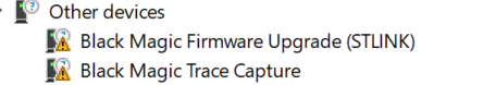
The 2 new COM ports appear (COM12,COM13), but i cant seem to flash anything successfully.
I've installed the GNU arm toolchain for windows and tried "target extended-remote \.\COM13" (12 just gets stuck on nothing), and i get:
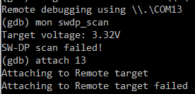
-
I just got my first NRF5 running. I'll note how I got it working in case any of you guys still have troubles:
Setup
- OS: Windows 10
- Programmer: STM32 Blue Pill with the Black Magic Probe firmware
- NRF5: EByte E73-TBB dev board with a E73-2G4M0S1B (NRF52832)
- Environment: PlatformIO
Instructions
Load the Black Magic Probe firmware with
stlinkas the probe host onto Blue Pill. You can follow this guide.Connect your new BMP to the NRF52 module:
BMP NRF52 Serial Port 3V3 3V3 GND GND A5 SWDCLK GDB Server B14 SWDIO GBD Server A2 RXI UART A3 TXO UART Note: A2 and A3 are not required for programming. This is how you'd wire up the BMP for "classic" serial debugging. You can use the BMP both for programming and serial communication - no need for a second FTDI module.
Using the GNU Arm Embedded Toolchain, run
arm-none-eabi-gdbin a console and enter the following commands to unlock the NRF52:target extended-remote BMP_GDB_SERVER_PORT mon swdp_scan attach N // N = number of "Nordic nRF52 Access Port" if there are several mon erase_mass detachFrom the two serial ports the BMP provides, you want to use the GDB Server for
BMP_GDB_SERVER_PORTabove. If Windows only provides generic names for both ("USB Serial Device" or something), the one with the lower number should (usually) be the right choice. If not, try the other one.Windows users also must prefix the port with
\\.\if the number is double-digit, e.g.\\.\COM13.Now you can start uploading sketches the usual way. Here's my minimal PlatformIO config:
[env:nrf52_dk]
platform = nordicnrf52
board = nrf52_dk
board_build.variant = generic
framework = arduino
upload_protocol = blackmagic
lib_deps =
	548 ; MySensors
And a minimal test sketch for MySensors:
#include <Arduino.h>

#define LED 17

#define MY_RADIO_RF24
#define MY_RADIO_NRF5_ESB
#define MY_NODE_ID 182

#define SKETCH_NAME "NRF52 Test"
#define SKETCH_VERSION "0.1"

#include <MySensors.h>

#define CHILD_ID 1
MyMessage msg(CHILD_ID, V_VAR1);

void presentation()
{
  sendSketchInfo(SKETCH_NAME, SKETCH_VERSION);
  present(CHILD_ID, S_CUSTOM);
}

void setup()
{
  pinMode(LED, OUTPUT);
}

void loop()
{
  static uint8_t num;
  send(msg.set(num));
  ++num;

  digitalWrite(LED, HIGH);
  wait(5000);
  digitalWrite(LED, LOW);
  wait(5000);
}
Works like a charm so far! Now, if you please excuse me, I have a whole new microprocessor family to explore. Fun times!
@BearWithBeard
Great explanation, thanks!
On my windows 10 installation I had to run Zadig to make the programming from platformIO work. -
@BearWithBeard
What did you do to get the serial pins of the Ebyte development board configured correctly, when using the generic board variant in platformIO? I've copied MyBoardNRF5.cpp but this is not used it seems.
Also redefining the definitions from variant.h#define PIN_SERIAL_TX (11) #define PIN_SERIAL_RX (12)doesn't give serial output.
-
@BearWithBeard
What did you do to get the serial pins of the Ebyte development board configured correctly, when using the generic board variant in platformIO? I've copied MyBoardNRF5.cpp but this is not used it seems.
Also redefining the definitions from variant.h#define PIN_SERIAL_TX (11) #define PIN_SERIAL_RX (12)doesn't give serial output.
@electrik Yeah, I ran into that issue, too. Not sure if that's the proper way to solve it, but I add a custom board directory to the build flags in platformio.ini ...
build_flags =
	-I $PROJECT_DIR/boards/generic
... and copied the board variant files from
.platformio/packages/framework-arduinonordicnrf5/variants/Generic/toboards/generic/in my project folder. Changes made in here aren't ignored or overwritten by global PIO definitions. -
@BearWithBeard Thanks that did it.
Could it be the TX and RX are switched on the BMP in your post?@electrik Good to hear. And yes, I think you are right. I'll swap them and change the naming to RXI and TXO to clarify the directionality. Thanks for the hint!
-
With respect to initial erase of NRF52, I have been using @BearWithBeard Black Magic Probe instructions successfully for years. But, my latest set of Minew boards doesn't respond.
I found that there is a new lock procedure from Nordic:I have tried upgrading my gdb and also J-Link EDU and nrfjprog tool chains and have not successfully connected to the new boards yet.
Has anyone had success with unlocking one of these new boards?
@nagelc Sorry I don't have an informed answer, but thanks for posting and making us aware of your experience with the minew's! Haven't heard from you in a while. Have you tried upgrading the firmware on the J-link that's part of a DK? I can't say that I have, but the firmware upgradeability was one of the alleged selling features of a DK's J-Link. That potential upgradeability didn't ever seem to matter, but maybe now it does.
As for me, after a long break I'm back to have a run at getting the nRF52805 to work. So far I've got bare metal blinking and bare metal UART working. I'm opting for bare metal code because it's unclear how well anything else will work with the nRF52805, which doesn't seem all that well supported. Soon to get some basic bare metal proprietary radio working, I hope.... If successful, I'll post it to github to memorialize it. There are surprisingly few examples of bare metal code out there, even though that's all the datasheet itself talks about. I guess I can understand why, because I've found some surprising ambiguities in the datasheet. For instance, who would have thought that PSELTXD would refer to an actual pin number and not to a bitmask? From the datasheet I thought for sure it would be a bitmask (like nearly everything else in the datasheet), but no, it's the actual pin number. I mean, why does the datasheet show literally every bit of a 32 bit word is relevant for specifying the pin number? On a different issue, bare metal UART doesn't work quite right without some artificial delays, even if driven by interrupt events, apparently because the actual generated baudrates aren't exactly right (something the datasheet admits). So, there's some finessing involved that you don't see when you're only working from abstracted libraries.
Regardless, the architecture itself remains pretty cool, and I enjoy it a lot!
-
After correcting a wiring error (duh!) I was able to erase using my J-Link Mini EDU.
I used Nordic's nrfjprog:
nrfjprog --family NRF52 --recover
nrfjprog --family NRF52 --recoverI had to run it twice to get the unlock. I think this makes sense after reading the devzone article.
Once unlocked, I could use my black magic probe for programming. I expect the blackmagic folks haven't had time to adapt to the new lock scheme yet. -
@nagelc Sorry I don't have an informed answer, but thanks for posting and making us aware of your experience with the minew's! Haven't heard from you in a while. Have you tried upgrading the firmware on the J-link that's part of a DK? I can't say that I have, but the firmware upgradeability was one of the alleged selling features of a DK's J-Link. That potential upgradeability didn't ever seem to matter, but maybe now it does.
As for me, after a long break I'm back to have a run at getting the nRF52805 to work. So far I've got bare metal blinking and bare metal UART working. I'm opting for bare metal code because it's unclear how well anything else will work with the nRF52805, which doesn't seem all that well supported. Soon to get some basic bare metal proprietary radio working, I hope.... If successful, I'll post it to github to memorialize it. There are surprisingly few examples of bare metal code out there, even though that's all the datasheet itself talks about. I guess I can understand why, because I've found some surprising ambiguities in the datasheet. For instance, who would have thought that PSELTXD would refer to an actual pin number and not to a bitmask? From the datasheet I thought for sure it would be a bitmask (like nearly everything else in the datasheet), but no, it's the actual pin number. I mean, why does the datasheet show literally every bit of a 32 bit word is relevant for specifying the pin number? On a different issue, bare metal UART doesn't work quite right without some artificial delays, even if driven by interrupt events, apparently because the actual generated baudrates aren't exactly right (something the datasheet admits). So, there's some finessing involved that you don't see when you're only working from abstracted libraries.
Regardless, the architecture itself remains pretty cool, and I enjoy it a lot!
-
After correcting a wiring error (duh!) I was able to erase using my J-Link Mini EDU.
I used Nordic's nrfjprog:
nrfjprog --family NRF52 --recover
nrfjprog --family NRF52 --recoverI had to run it twice to get the unlock. I think this makes sense after reading the devzone article.
Once unlocked, I could use my black magic probe for programming. I expect the blackmagic folks haven't had time to adapt to the new lock scheme yet.@nagelc said in GUIDE - NRF5 / NRF51 / NRF52 for beginners:
After correcting a wiring error (duh!) I was able to erase using my J-Link Mini EDU.
I used Nordic's nrfjprog:
nrfjprog --family NRF52 --recover
nrfjprog --family NRF52 --recoverI had to run it twice to get the unlock. I think this makes sense after reading the devzone article.
Once unlocked, I could use my black magic probe for programming. I expect the blackmagic folks haven't had time to adapt to the new lock scheme yet.For future reference, yet another way you can also erase your chip is using the "Programmer" app that you can install into "nRF Connect for Desktop" program. Just connect and press the "Erase All" button:
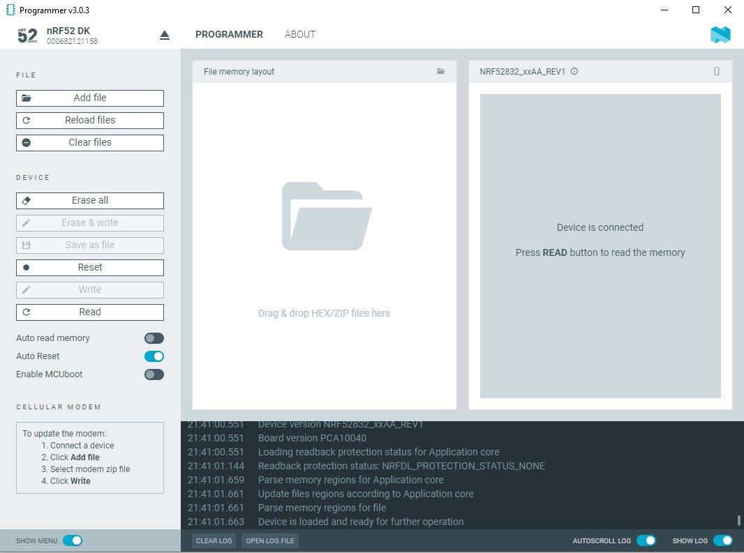
I find that I have to do this in order to unlock the chip for the first time prior to enabling the reset pin with the code:
// Note: if chip has never been mass erased, then most likely PSELRESET[0] and PSELRESET[1] are both zero. // When that is the case, the chip is locked and neither can be set to 21. if (((NRF_UICR-> PSELRESET[0])==0xFFFFFFFF) && ((NRF_UICR-> PSELRESET[1])==0xFFFFFFFF)) { //if the two RESET registers were erased by a mass erase NRF_NVMC->CONFIG=1; // Write enable the UICR //Note: BOTH registers must be set to 21, or else PIN00.21 will not function as a RESET pin. NRF_UICR-> PSELRESET[0]= 21; //designate pin P0.21 as the RESET pin NRF_UICR-> PSELRESET[1]= 21; //designate pin P0.21 as the RESET pin NRF_NVMC->CONFIG=0; // Put the UICR back into read-only mode. } -
Well, I take it back. Although the above method worked for doing an "erase-all" and unlock the nRF52832 that's built into the nRF52-DK, it isn't doing anything to unlock a nRF52805 that's externally connected to an nRF52-DK. "Erase all" does seem to erase the program that on the nRF52805, but it nonetheless doesn't allow access to the reset registers NRF_UICR-> PSELRESET[0] and NRF_UICR-> PSELRESET[1]. I say that because, for instance, NRF_UICR-> PSELRESET[0] and NRF_UICR-> PSELRESET[1] are still zero after the "erase all" instead of 0xFFFFFFFF, and attempting to write them both to 21 fails.
I also tried nrfjprog:
nrfjprog --erase all
nrfjprog --recover
nrfjprog --resetpinenable
nrfjprog --family NRF52 --recover
nrfjprog --family UNKNOWN --recover
nrfjprog --eraseuicrand after each try the nRF52805 still has the reset registers impervious to writing.
Well, I see that the nRF52805 has been blessed with some kind of fancy new access port protection (APPROTECT), but reading the value of NRF_UICR->APPROTECT, it is currently at 0xFFFFFFFF, which means that APPROTECT is disabled.
So, not sure what to do about this one.
-
For anyone who may be interested, this is what the current draw on an nRF52805 looks like when it's sleeping:
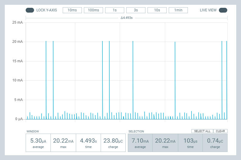
It's about the same whether it's using DCDC mode or LDO mode when the system is sleeping in ON mode. When I first saw this plot I thought the MCU was waking up, doing something, and then falling back to sleep on what seemed like a very repeatable periodicity. I even went hunting for some part of the system that I had forgotten to turn-off that might be causing this behavior. However, when that hunt didn't turn up anything, my present theory is that this is just how the low power mode works when the system is ON but in sleep mode: it maybe is more efficient to sip current at periodic intervals than it is to run the LDO/DCDC continuously.
Now that you've seen the above picture of the spikey nature in which a nRF52 module draws its sleep current, you can appreciate that using a uCurrent Gold or a Current Ranger (let alone a multimeter) to measure sleep current is likely to give an erroneously low measurement: these pulses pass by too quickly for such a meter to properly register. That's why, for instance, I began to suspect that this guy's measurements were possibly too low:
https://www.youtube.com/watch?v=7sMbcyYS9osIndeed, when I hook my same sleeping module up to a current ranger, the current ranger shows 0.0ua when set in ua mode. In na mode, though, the measurements are jumping around all over the place. The point being: if that was all I had to go on, I'd probably erroneously conclude that the sleep current was something less than 1ua, whereas the PPK2 here is reporting an average 5.3ua within its measurement window.
What remains unexplained is why the average current draw I measured with PPK2 while sleeping like this is so high. According to the nRF52805 datasheet, the current drawn while sleeping in system ON mode with full memory retention should be just 0.8ua.
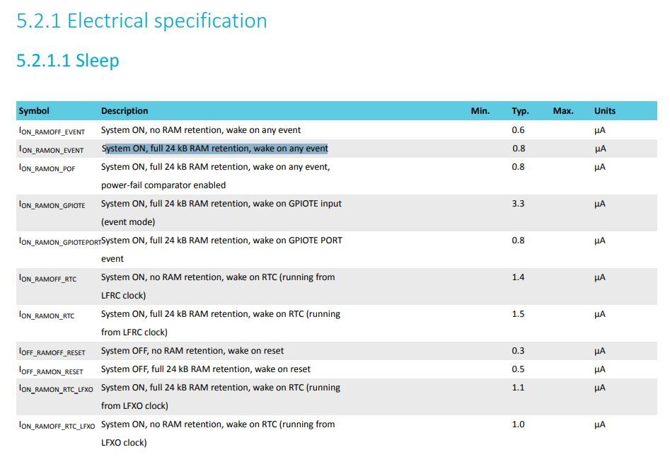
and so I'm not sure why I'm experiencing so much more than that (5.3ua in this PPK2 example), unless maybe it's something about the Fanstel BC805M module that it's a part of which is raising the sleep current. If so, that would certainly be disappointing: I bought it precisely because the nRF52805 is supposed to have such a low sleep current compared to the other Nordic nRF52 chips that are out there.
As a matter of fact, the spikey nature of the current draws led me to wonder whether maybe the PPK2 itself was perhaps not measuring the current correctly. So, to answer that, I added a 220uF bypass ceramic capacitor (i.e. between VCC and GND) near the nRF52805 module to better average out the current draw seen by the PPK2, and then I measured using the PPK2 again. Guess what? Now the PPK2 measures an average of 0.81ua, which is spot-on with what the datasheet predicted. Whew! What a relief. I find this new measurement trustworthy not only because (a) it agrees with the value predicted by the datasheet, but now also (b) both a PPK2 and a Current Ranger produce current measurements that agree with one another, and (c) by averaging out the current draw, the potential problems stemming from a highly spikey measurement are cast aside.
-
For anyone who may be interested, this is what the current draw on an nRF52805 looks like when it's sleeping:
It's about the same whether it's using DCDC mode or LDO mode when the system is sleeping in ON mode. When I first saw this plot I thought the MCU was waking up, doing something, and then falling back to sleep on what seemed like a very repeatable periodicity. I even went hunting for some part of the system that I had forgotten to turn-off that might be causing this behavior. However, when that hunt didn't turn up anything, my present theory is that this is just how the low power mode works when the system is ON but in sleep mode: it maybe is more efficient to sip current at periodic intervals than it is to run the LDO/DCDC continuously.
Now that you've seen the above picture of the spikey nature in which a nRF52 module draws its sleep current, you can appreciate that using a uCurrent Gold or a Current Ranger (let alone a multimeter) to measure sleep current is likely to give an erroneously low measurement: these pulses pass by too quickly for such a meter to properly register. That's why, for instance, I began to suspect that this guy's measurements were possibly too low:
https://www.youtube.com/watch?v=7sMbcyYS9osIndeed, when I hook my same sleeping module up to a current ranger, the current ranger shows 0.0ua when set in ua mode. In na mode, though, the measurements are jumping around all over the place. The point being: if that was all I had to go on, I'd probably erroneously conclude that the sleep current was something less than 1ua, whereas the PPK2 here is reporting an average 5.3ua within its measurement window.
What remains unexplained is why the average current draw I measured with PPK2 while sleeping like this is so high. According to the nRF52805 datasheet, the current drawn while sleeping in system ON mode with full memory retention should be just 0.8ua.
and so I'm not sure why I'm experiencing so much more than that (5.3ua in this PPK2 example), unless maybe it's something about the Fanstel BC805M module that it's a part of which is raising the sleep current. If so, that would certainly be disappointing: I bought it precisely because the nRF52805 is supposed to have such a low sleep current compared to the other Nordic nRF52 chips that are out there.
As a matter of fact, the spikey nature of the current draws led me to wonder whether maybe the PPK2 itself was perhaps not measuring the current correctly. So, to answer that, I added a 220uF bypass ceramic capacitor (i.e. between VCC and GND) near the nRF52805 module to better average out the current draw seen by the PPK2, and then I measured using the PPK2 again. Guess what? Now the PPK2 measures an average of 0.81ua, which is spot-on with what the datasheet predicted. Whew! What a relief. I find this new measurement trustworthy not only because (a) it agrees with the value predicted by the datasheet, but now also (b) both a PPK2 and a Current Ranger produce current measurements that agree with one another, and (c) by averaging out the current draw, the potential problems stemming from a highly spikey measurement are cast aside.
-
@NeverDie have you checked the radio already? How much work is needed to make it work with mysensors?
@monte said in GUIDE - NRF5 / NRF51 / NRF52 for beginners:
@NeverDie have you checked the radio already? How much work is needed to make it work with mysensors?
Answering your question: Presently taking baby steps. Using pseudo bare metal programming I have it sending and receiving very simple packets using the proprietary mode radio at 2mbps. Nothing fancy. Just the bare minimum. But it works, and the code is portable with no meaningful library dependencies other than just regular C-language libraries like string.h. :-) After I clean up the code I'll post it to github. I had already posted it on github in micropython and forth, and I just recently translated it back into C (which is what I had started with originally but didn't save the code :face_with_rolling_eyes: ). Anyhow, the benefit of writing it in pseudo bare metal is that it should pretty much compile without changes and run no matter which tool chain you're using (Sandeep, SES, or whatever). :slightly_smiling_face:
You know, it occurs to me that we should upload not just the source code, but a full VM of the development environment used to compile, link, and upload it. That would be smart. After all, all projects become time capsules, and who knows what toolchain or library will be in vogue years down the line when you want to make some change in the code you've written. If it's all in a VM, then you can step back right where you were without missing a beat. Hmmm.... I like this idea. So obvious, yet so powerful. The only problem I foresee is that J-link license is bound to the particular nRF52-DK that you own, so at least that part might make sharing a common VM a bit awkward. Everything would need to be either open source or free to use for a shared VM to work without incurring problems of its own.
But, anyway, details aside, a shared VM development platform would create a stable starting place for any newcomer who comes along. Even if the setup instructions are current at the moment they are written, over time entropy kicks in and eventually....you all know how that goes.....
And not just SW development. HW development too. For instance, rather than share just a kicad archive, if you could share a VM of the entire kiCad that you used to create a PCB.... that would be the ultimate. Then, if KiCad 7 comes along and isn't fully backward compatible with KiCad 6, everything still works just as well as it always did the moment you finished with it.
-
@monte said in GUIDE - NRF5 / NRF51 / NRF52 for beginners:
@NeverDie are you saying it is only programmable with j-link? Won't stlink/blackmagic work?
:face_palm: Yes, you're right. Either of those should work. I happen to be using j-link, so that gave me tunnel vision, but if either or those were the basis, then problem solved!
BTW, I just now checked, and the module I'm using literally does fit on a dime:
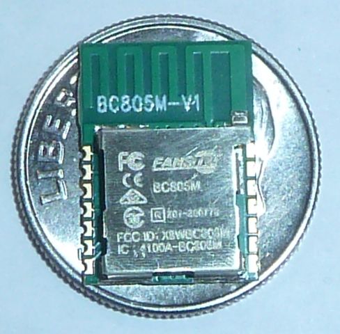
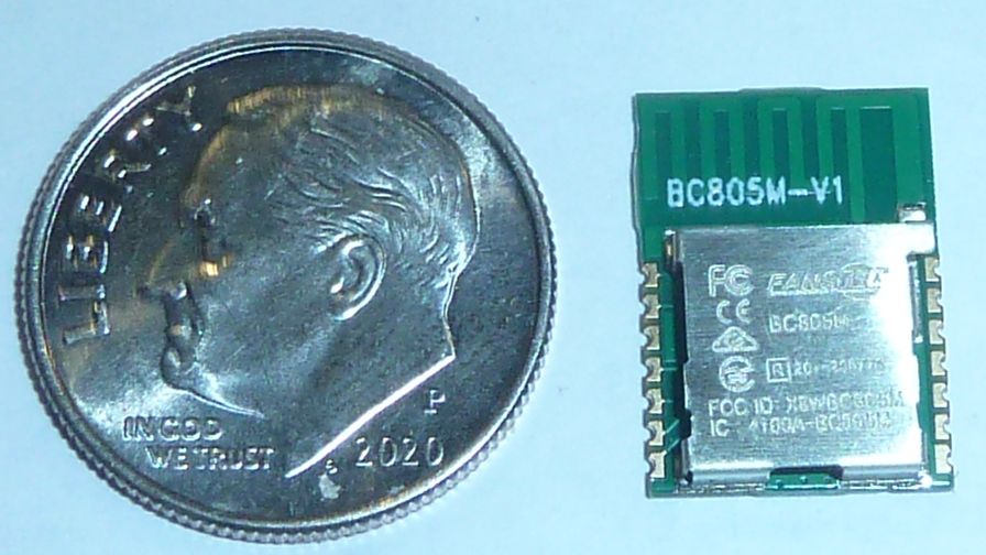
$2.50 each. -
@monte said in GUIDE - NRF5 / NRF51 / NRF52 for beginners:
@NeverDie are you saying it is only programmable with j-link? Won't stlink/blackmagic work?
:face_palm: Yes, you're right. Either of those should work. I happen to be using j-link, so that gave me tunnel vision, but if either or those were the basis, then problem solved!
BTW, I just now checked, and the module I'm using literally does fit on a dime:
$2.50 each. -
@monte said in GUIDE - NRF5 / NRF51 / NRF52 for beginners:
@NeverDie sorry, where did you buy them? I don't see them anywhere :(
https://www.fanstel.com/buy/bt832f-low-cost-longer-range-bluetooth-50-module-cjtrx-8shlz-r7a7z
Presently sold-out of this particular model, but if you watch for it, it seems to come back into stock fairly often. When I was buying they had only 10 in stock, so I bought all ten. Then the next day they had another 15 in stocki, so I bought all 15. Then they were out of stock for a while, but then recently they re-stocked. Apparently that didn't last, because now they are already out of stock again.