Everything nRF52840
-
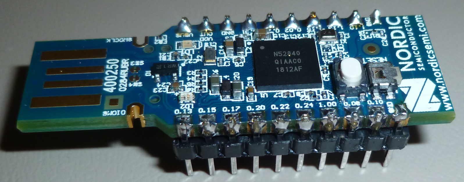
@scalz and @NeverDie today I got my nRF52840 dongles (6 pieces) as well as the TI CC1352P1 launchpad. Now the fun will begin (latest at the weekend)
See the picture below (the dongle in blue and the launchpad in red).
If you have already some more code to share for testing (send/receive, I2C sensor read etc.) please post it (some code was postetd by NeverDie) other wise I'm looking at the Nordic pages, they provide a lot of examples (I will probably use/try Segger).
For the TI part, I only have one launchpad, so I have to verify, if I can use BLE 5.0 to communicate with my mobile or between TI CC1352 and nRF52 ...
Not sure if the TI can also communicate with the CC1101 at 868MHz (using the Sub 1GHz capabilities) using the same modem settings. So a lot to find out.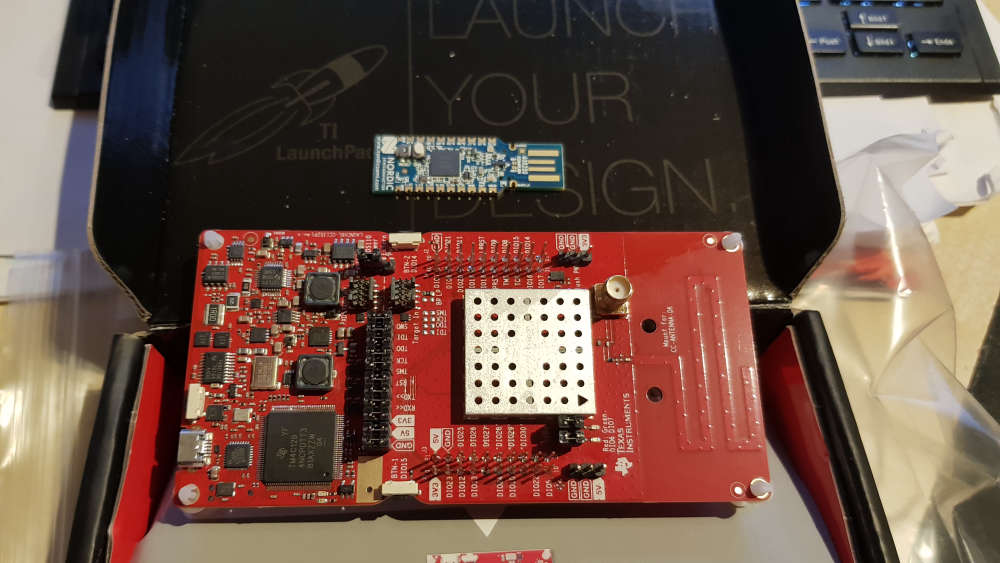
-
@scalz and @NeverDie today I got my nRF52840 dongles (6 pieces) as well as the TI CC1352P1 launchpad. Now the fun will begin (latest at the weekend)
See the picture below (the dongle in blue and the launchpad in red).
If you have already some more code to share for testing (send/receive, I2C sensor read etc.) please post it (some code was postetd by NeverDie) other wise I'm looking at the Nordic pages, they provide a lot of examples (I will probably use/try Segger).
For the TI part, I only have one launchpad, so I have to verify, if I can use BLE 5.0 to communicate with my mobile or between TI CC1352 and nRF52 ...
Not sure if the TI can also communicate with the CC1101 at 868MHz (using the Sub 1GHz capabilities) using the same modem settings. So a lot to find out.@heinzv Please do keep us posted with your impressions as you develop them.
I found out that Nordic does have OTA firmware updates, though it looks rather laborioius to set up: https://devzone.nordicsemi.com/b/blog/posts/getting-started-with-nordics-secure-dfu-bootloader
Maybe it's easier with TI (?).
-
@NeverDie okay, a very first testing yesterday late-night when setting up the Segger / nRF52(840) tool chain and a very quick dongle testing
I used the nRFconnect and uploaded all 5 demo/test applications which worked. No big achievement but just a very basic testing (maybe not even worth to mention)
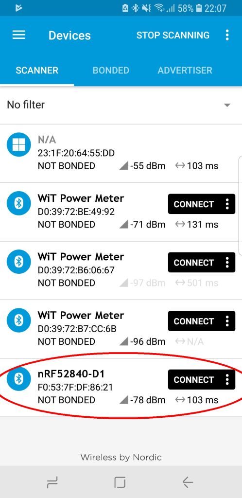
Here is the result of the BLE app test: I did the BLE scan with the dongle and it found some devices around such as the BLE WiT power plug with the energy meter. Thene I did the oposite and installed the nRF connect on the Android Galaxy S8 phone and scanned for the nRF dongle.
Attached the two results (one from the dongle and one from the mobile phone)
As you see the Galaxy S8 finds all BLE WiT smart plugs in the flat (also the ones which are in other rooms) while the nRF dongle sees only the one which is close in the same room.
I would assume, that the Galaxy S8 has a much better BLE antenna than the dongle (which has almost no antenna), but what I interpret the RSSI, the dongle reports a better signal strength of the WiT powermeter in the room?!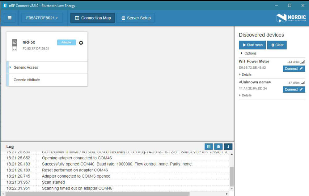
Today I received also the breakout PCB's for the nRF52832, thus I'll probably try to do a sender/receiver test with them using one as mySensors Gateway and one as mySensors Node (both in nRF24 mode). Not sure if the compile/build will work, because I have to also provide the proper pin-map (as the E73 module is not mapped in the Arduino IDE).
-
@NeverDie okay, a very first testing yesterday late-night when setting up the Segger / nRF52(840) tool chain and a very quick dongle testing
I used the nRFconnect and uploaded all 5 demo/test applications which worked. No big achievement but just a very basic testing (maybe not even worth to mention)
Here is the result of the BLE app test: I did the BLE scan with the dongle and it found some devices around such as the BLE WiT power plug with the energy meter. Thene I did the oposite and installed the nRF connect on the Android Galaxy S8 phone and scanned for the nRF dongle.
Attached the two results (one from the dongle and one from the mobile phone)
As you see the Galaxy S8 finds all BLE WiT smart plugs in the flat (also the ones which are in other rooms) while the nRF dongle sees only the one which is close in the same room.
I would assume, that the Galaxy S8 has a much better BLE antenna than the dongle (which has almost no antenna), but what I interpret the RSSI, the dongle reports a better signal strength of the WiT powermeter in the room?!
Today I received also the breakout PCB's for the nRF52832, thus I'll probably try to do a sender/receiver test with them using one as mySensors Gateway and one as mySensors Node (both in nRF24 mode). Not sure if the compile/build will work, because I have to also provide the proper pin-map (as the E73 module is not mapped in the Arduino IDE).
-
Found these relatively inexpensive TI modules:
https://www.ebay.com/itm/REYAX-RYB080I-BT-4-2-5-0-Bluetooth-module-BLE-TI-CC2640R2F-Antenna-AT-Command/183413364598?hash=item2ab449d776:g:dOEAAOSwOZtbRu7Athat presumably are compatible, at some level, with ti's cc2640R2F launchpad
Also, I found the info on how to do the OAD (over the air download): http://dev.ti.com/tirex/content/simplelink_cc2640r2_sdk_1_30_00_25/docs/blestack/ble_sw_dev_guide/html/oad/oad.html
Regarding the Nordic gear, I'm hoping that micropython, if installed, might prove to be easiest for OTA updates, since, in theory, a micropython app should be able to update itself through its inherent REPL process. It turns out that maybe because of the BBC micro bit, micropython runs on the nRF51. In general, though, it seems like the ESP8266 has a lot more micropython support.
-
@NeverDie I'm still at the basics (where you have been probably one year ago). I have now soldered my nRF52832 modules (the E73...B from EBYTE) to the breakout boards and tried to find the best way to program and flash them.
I started with Segger Studio and with ST-Link upgraded to Black Magic Probe but as far as I have understood it supports only their own J-Link HW for flashing (at least the J-Link EDU is required). I also converted a ST-Link Dongle to a J-Link dongle but that can only flash STM MCU's (license restrictions).I have then tried to use Aruino Studio with all 3 dongle types (Black Magic, J-Link and ST-Link). I was only successful by using ST-Link. It does flashes the sketches and it runs (just used a simple blink example for flash testing).
But using the ST-Link (V2), there is no serial devices and thus no Serial Windows for log output (Serial.println()).
I've also tried to use the Black Magics with the GDB but it did not work either and I found it also not convinient with the commandline.So what are you using for flashing with Arduino Studio (with it's limited nRF52 support) and flashing with Segger Studio an what are you using for debugging and logging (print lines to output/serial ...)?
@heinzv For the NRF52832, try using the MySensors MyBoardNRF5 board type. In MyBoardNRF5.h, there is a section for the serial interface. Set PIN_SERIAL_TX to the pin you want to get serial output from. Set PIN_Serial_RX to some unused pin. It isn't used anyway. (A tip I got from @NeverDie).
I like the Black Magic Probe because it has both the SWD and Serial in one device, but you could program with the ST-Link and listen to Serial with an FTDI. I hear J-Link is the best, but have not used it. Might try it now that I know there is an educational version. -
@NeverDie I'm still at the basics (where you have been probably one year ago). I have now soldered my nRF52832 modules (the E73...B from EBYTE) to the breakout boards and tried to find the best way to program and flash them.
I started with Segger Studio and with ST-Link upgraded to Black Magic Probe but as far as I have understood it supports only their own J-Link HW for flashing (at least the J-Link EDU is required). I also converted a ST-Link Dongle to a J-Link dongle but that can only flash STM MCU's (license restrictions).I have then tried to use Aruino Studio with all 3 dongle types (Black Magic, J-Link and ST-Link). I was only successful by using ST-Link. It does flashes the sketches and it runs (just used a simple blink example for flash testing).
But using the ST-Link (V2), there is no serial devices and thus no Serial Windows for log output (Serial.println()).
I've also tried to use the Black Magics with the GDB but it did not work either and I found it also not convinient with the commandline.So what are you using for flashing with Arduino Studio (with it's limited nRF52 support) and flashing with Segger Studio an what are you using for debugging and logging (print lines to output/serial ...)?
@heinzv I use the Nordic development kit for flashing. At least for me, it's the easiest.
-
@heinzv I use the Nordic development kit for flashing. At least for me, it's the easiest.
@neverdie said in Everything nRF52840:
@heinzv I use the Nordic development kit for flashing. At least for me, it's the easiest.
Same here. NFR52 DK, works perfectly with Segger ES and I just do drag & drop of the compiled file to the virtual drive of the DK when using Arduino.
-
@heinzv I use the Nordic development kit for flashing. At least for me, it's the easiest.
@neverdie and @Nca78 thanks for the quick response, I have ordered the nRF52840 DK from Nordic (via Mouser). That works with Segger and also with Arduino Studio too (for the simple and existing 52832 projects like mySensors)?
And fo the Arduino Studio (or VS Code) is there a serial terminal for debug output too?
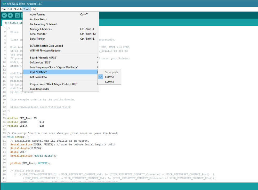
How to you flash then the bare nRF52 modules which have only the SWD interface (I have plenty of them)?@nagelc I have again tried my Black Magic Probe Dongle with Arduino IDE, but it does not yet work for me (maybe I still have not understood it). In Arduino Studio I have tge GDB serial port but neither the upload works properly nor I have understood how to use it with the GDB debug window.
I attach the devices (Windows 10) and the output from Arduino IDE. Maybe you can give me further hints:
I used a simple blink sketch which works with ST-LInk V2 upload but not with BMP. Here is the output from the upload:
Sketch uses 3600 bytes (0%) of program storage space. Maximum is 409600 bytes.
Target voltage: unknown
Remote debugging using \.\COM58
Available Targets:
No. Att Driver
1 Nordic nRF52
2 Nordic nRF52 Access Port
Attaching to Remote target
0x00000ad0 in ?? ()
Reading symbols from nRF52832_Blink.ino.elf...done.
Loading section .text, size 0xe10 lma 0x1c000
Loading section .ARM.exidx, size 0x8 lma 0x1ce10
Loading section .data, size 0x74 lma 0x1ce18
Start address 0x1c5fc, load size 3724
Transfer rate: 26 KB/sec, 620 bytes/write.
Temporary breakpoint 1 at 0x1cb4c: file D:\mcdev\arduino\portable\packages\sandeepmistry\hardware\nRF5\0.6.0\cores\nRF5\main.cpp, line 28.
Starting program: C:\Users\internet\AppData\Local\Temp\arduino_build_189520\nRF52832_Blink.ino.elf
Note: automatically using hardware breakpoints for read-only addresses.
An error occurred while uploading the sketch -
@neverdie and @Nca78 thanks for the quick response, I have ordered the nRF52840 DK from Nordic (via Mouser). That works with Segger and also with Arduino Studio too (for the simple and existing 52832 projects like mySensors)?
And fo the Arduino Studio (or VS Code) is there a serial terminal for debug output too?
How to you flash then the bare nRF52 modules which have only the SWD interface (I have plenty of them)?@nagelc I have again tried my Black Magic Probe Dongle with Arduino IDE, but it does not yet work for me (maybe I still have not understood it). In Arduino Studio I have tge GDB serial port but neither the upload works properly nor I have understood how to use it with the GDB debug window.
I attach the devices (Windows 10) and the output from Arduino IDE. Maybe you can give me further hints:
I used a simple blink sketch which works with ST-LInk V2 upload but not with BMP. Here is the output from the upload:
Sketch uses 3600 bytes (0%) of program storage space. Maximum is 409600 bytes.
Target voltage: unknown
Remote debugging using \.\COM58
Available Targets:
No. Att Driver
1 Nordic nRF52
2 Nordic nRF52 Access Port
Attaching to Remote target
0x00000ad0 in ?? ()
Reading symbols from nRF52832_Blink.ino.elf...done.
Loading section .text, size 0xe10 lma 0x1c000
Loading section .ARM.exidx, size 0x8 lma 0x1ce10
Loading section .data, size 0x74 lma 0x1ce18
Start address 0x1c5fc, load size 3724
Transfer rate: 26 KB/sec, 620 bytes/write.
Temporary breakpoint 1 at 0x1cb4c: file D:\mcdev\arduino\portable\packages\sandeepmistry\hardware\nRF5\0.6.0\cores\nRF5\main.cpp, line 28.
Starting program: C:\Users\internet\AppData\Local\Temp\arduino_build_189520\nRF52832_Blink.ino.elf
Note: automatically using hardware breakpoints for read-only addresses.
An error occurred while uploading the sketch@heinzv I haven't ever used BMP, but I'm guessing that maybe you need to bulk erase your target device first. That would remove any read-only protection. If so, you only need to do it once. After that, it should upload OK.
-
@heinzv I haven't ever used BMP, but I'm guessing that maybe you need to bulk erase your target device first. That would remove any read-only protection. If so, you only need to do it once. After that, it should upload OK.
-
@neverdie I can do upload with the standard ST-Link V2 Dongle on the same bare E73 module but for the BMP it is read-only?
How do you flash the bare modules (not the DK)?@heinzv said in Everything nRF52840:
@neverdie I can do upload with the standard ST-Link V2 Dongle on the same bare E73 module but for the BMP it is read-only?
How do you flash the bare modules (not the DK)?Not sure I understand your question. I can flash bare modules using the DK. I'll let others comment how they do it without using the DK, as that's about all I know. One final tip though: Generally it's important to power your target module independently of whatever programmer you're using. For instance, on the DK, it will detect the voltage level on the target and adjust accordingly, but it isn't meant to power the target.
-
@heinzv said in Everything nRF52840:
@neverdie I can do upload with the standard ST-Link V2 Dongle on the same bare E73 module but for the BMP it is read-only?
How do you flash the bare modules (not the DK)?Not sure I understand your question. I can flash bare modules using the DK. I'll let others comment how they do it without using the DK, as that's about all I know. One final tip though: Generally it's important to power your target module independently of whatever programmer you're using. For instance, on the DK, it will detect the voltage level on the target and adjust accordingly, but it isn't meant to power the target.
@neverdie To my first statement: I was just wondering why I can upload sketches with teh ST-Link V2 dongle (but no serial output/debug windows) but the BMP might face read-only protection (I thin kthe upload script should have some kind of mass erase before upload)?
Regarding my question: I think I you understood my question right and I also read the nRF DK features and it says it features a SEGGER J-Link OB Debugger with debug out functionality. So I guess it's a flasher/debugger not only for it's on-board nRF52840 MCU but also for external nRF modules connected to the DK right?Are you're also using the DK with the Arduino IDE (though with restrictions like no full nRF52840 support) and the mySensors project?
Meanwhile I'm exploring the nRF52840 USB dongles. And maybe I'll get along with the BMP modules and understand how the work with the Arduino IDE (so far I spent many hours with Google und no success).
-
@neverdie To my first statement: I was just wondering why I can upload sketches with teh ST-Link V2 dongle (but no serial output/debug windows) but the BMP might face read-only protection (I thin kthe upload script should have some kind of mass erase before upload)?
Regarding my question: I think I you understood my question right and I also read the nRF DK features and it says it features a SEGGER J-Link OB Debugger with debug out functionality. So I guess it's a flasher/debugger not only for it's on-board nRF52840 MCU but also for external nRF modules connected to the DK right?Are you're also using the DK with the Arduino IDE (though with restrictions like no full nRF52840 support) and the mySensors project?
Meanwhile I'm exploring the nRF52840 USB dongles. And maybe I'll get along with the BMP modules and understand how the work with the Arduino IDE (so far I spent many hours with Google und no success).
@heinzv said in Everything nRF52840:
Regarding my question: I think I you understood my question right and I also read the nRF DK features and it says it features a SEGGER J-Link OB Debugger with debug out functionality. So I guess it's a flasher/debugger not only for it's on-board nRF52840 MCU but also for external nRF modules connected to the DK right?
Right.
Are you're also using the DK with the Arduino IDE (though with restrictions like no full nRF52840 support) and the mySensors project?
Not presently. I made a weak attempt recently but something is broken (probably on my end) to where I couldn't get it to compile anymore, whereas previously I could. So, I decided to see what else was available, which led me to mbed, and then now to SES, which has no trouble compiling. As long as I can directly manipulate the nRF52 registers and have access to serial output for debugging, I can do pretty much do whatever I need to do.
-
@alowhum said in Everything nRF52840:
The easiest way to get started with NRF5 might actually be the BBC Micro:bit :-)
Yes! From what I can tell, a lot of development work has gone into the micro bit to make it easily programmable using any of a handful of different languages including C, C++, and micropython. Apparently it's somehow possible to do a hybrid of C and micropython, where the time sensitive parts can be written in C/C++ and the rest in micropython. Not sure how that works exactly, but it sounds interesting.
Originally I thought the BBC micro bit was purely a toy, but when I saw it could scroll text across its 5x5 matrix of LED's I realized that it could be more than that. Very clever!
You can also program the microbit using the Arduino IDE:
https://learn.adafruit.com/use-micro-bit-with-arduinoMy hope is that somewhere there's an easy-to-use way to:
- Do OTA updates.
- Interface with bluetooth.
It seems there may be a way to OTA update the micro bit, probably from a bluetooth phone:
https://phwallen.github.io/microbit-swift/What I'd prefer, obviously, is doing the OTA update from a computer (maybe using a dongle of some kind?) If that were possible, then nRF51 modules are so cheap you could imagine putting them in almost anything, even if it's to control a different kind of radio.
-
@neverdie and @Nca78 thanks for the quick response, I have ordered the nRF52840 DK from Nordic (via Mouser). That works with Segger and also with Arduino Studio too (for the simple and existing 52832 projects like mySensors)?
And fo the Arduino Studio (or VS Code) is there a serial terminal for debug output too?
How to you flash then the bare nRF52 modules which have only the SWD interface (I have plenty of them)?@nagelc I have again tried my Black Magic Probe Dongle with Arduino IDE, but it does not yet work for me (maybe I still have not understood it). In Arduino Studio I have tge GDB serial port but neither the upload works properly nor I have understood how to use it with the GDB debug window.
I attach the devices (Windows 10) and the output from Arduino IDE. Maybe you can give me further hints:
I used a simple blink sketch which works with ST-LInk V2 upload but not with BMP. Here is the output from the upload:
Sketch uses 3600 bytes (0%) of program storage space. Maximum is 409600 bytes.
Target voltage: unknown
Remote debugging using \.\COM58
Available Targets:
No. Att Driver
1 Nordic nRF52
2 Nordic nRF52 Access Port
Attaching to Remote target
0x00000ad0 in ?? ()
Reading symbols from nRF52832_Blink.ino.elf...done.
Loading section .text, size 0xe10 lma 0x1c000
Loading section .ARM.exidx, size 0x8 lma 0x1ce10
Loading section .data, size 0x74 lma 0x1ce18
Start address 0x1c5fc, load size 3724
Transfer rate: 26 KB/sec, 620 bytes/write.
Temporary breakpoint 1 at 0x1cb4c: file D:\mcdev\arduino\portable\packages\sandeepmistry\hardware\nRF5\0.6.0\cores\nRF5\main.cpp, line 28.
Starting program: C:\Users\internet\AppData\Local\Temp\arduino_build_189520\nRF52832_Blink.ino.elf
Note: automatically using hardware breakpoints for read-only addresses.
An error occurred while uploading the sketch@heinzv I'm running a different sketch, but I get almost the same output as you except at the end: instead of "An error occured . . .":
Note: automatically using hardware breakpoints for read-only addresses.

Temporary breakpoint 1, main ()
    at D:\carln\Documents\Arduino\libraries\MySensors/hal/architecture/NRF5/MyMainNRF5.cpp:23
23	{

Program complete!
There are a couple of differences.
" Sketch uses 17856 bytes (3%) of program storage space. Maximum is 524288 bytes."
Not sure why my maximum storage space would be higher than yours.
"Start address 0x2fa0, load size 18080"
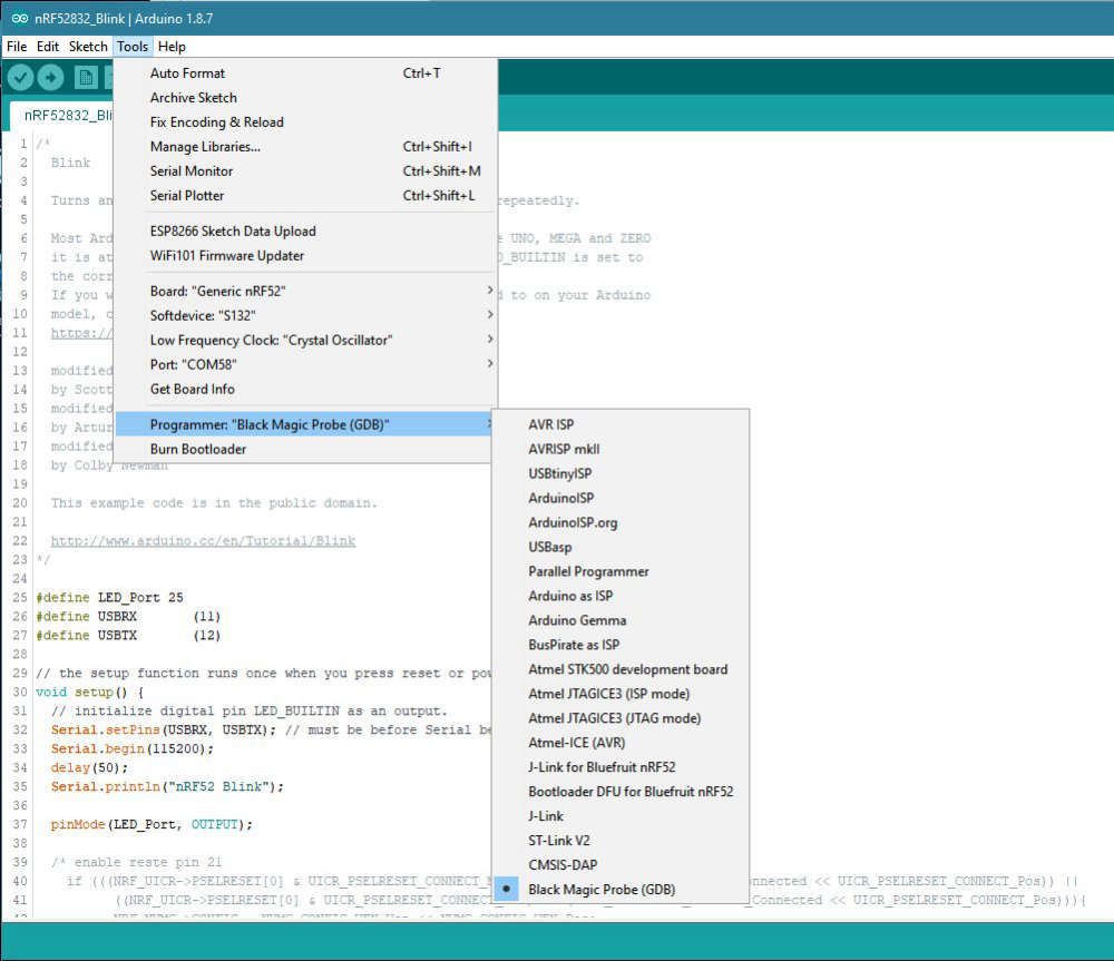
Different sketch, so I would not expect the load size to match, but not sure why the Start address would be different.On the Arduino Tools tab, are you selecting Bootloader/SD: None?
-
@heinzv I'm running a different sketch, but I get almost the same output as you except at the end: instead of "An error occured . . .":
Note: automatically using hardware breakpoints for read-only addresses.

Temporary breakpoint 1, main ()
    at D:\carln\Documents\Arduino\libraries\MySensors/hal/architecture/NRF5/MyMainNRF5.cpp:23
23	{

Program complete!
There are a couple of differences.
" Sketch uses 17856 bytes (3%) of program storage space. Maximum is 524288 bytes."
Not sure why my maximum storage space would be higher than yours.
"Start address 0x2fa0, load size 18080"
Different sketch, so I would not expect the load size to match, but not sure why the Start address would be different.On the Arduino Tools tab, are you selecting Bootloader/SD: None?
@nagelc Thanks for your response and trying to get me further.
I'm trying to get you as much infos as possible:
I made a couple of screenshots and picture of my environment. Maybe that helps to trace down to the problem.
I followed exactly the instructions from sanseeps Arduino/nRF5 configuration/installation.
Uploading the bkink example with the ST-Link V2 works, but there is no serial print, no debug, thus I'm trying the BMP way.Here some setttings from my Arduino IDE (Tools section)
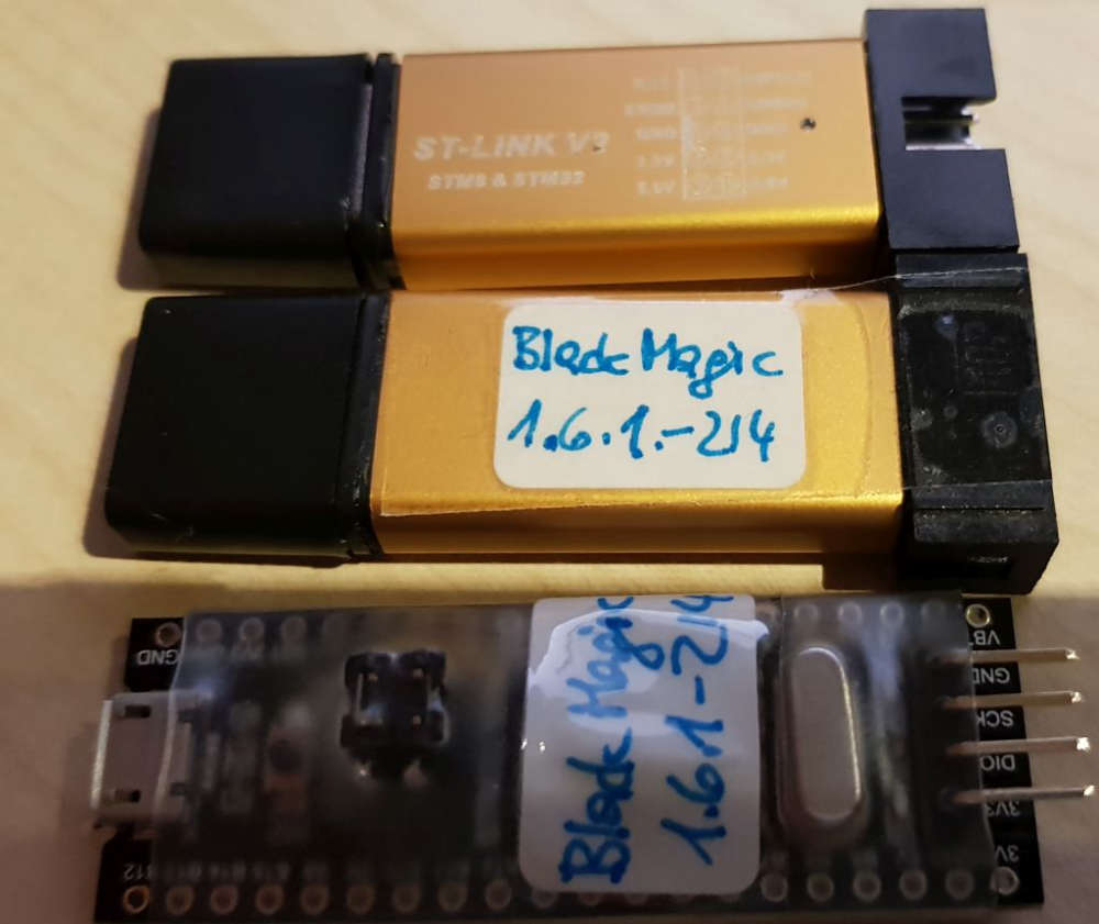
Here are my different BMP modules I have used
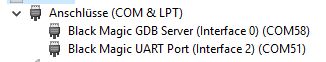
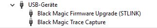
and the COM devices in Win 10
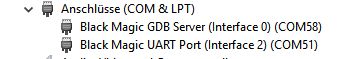
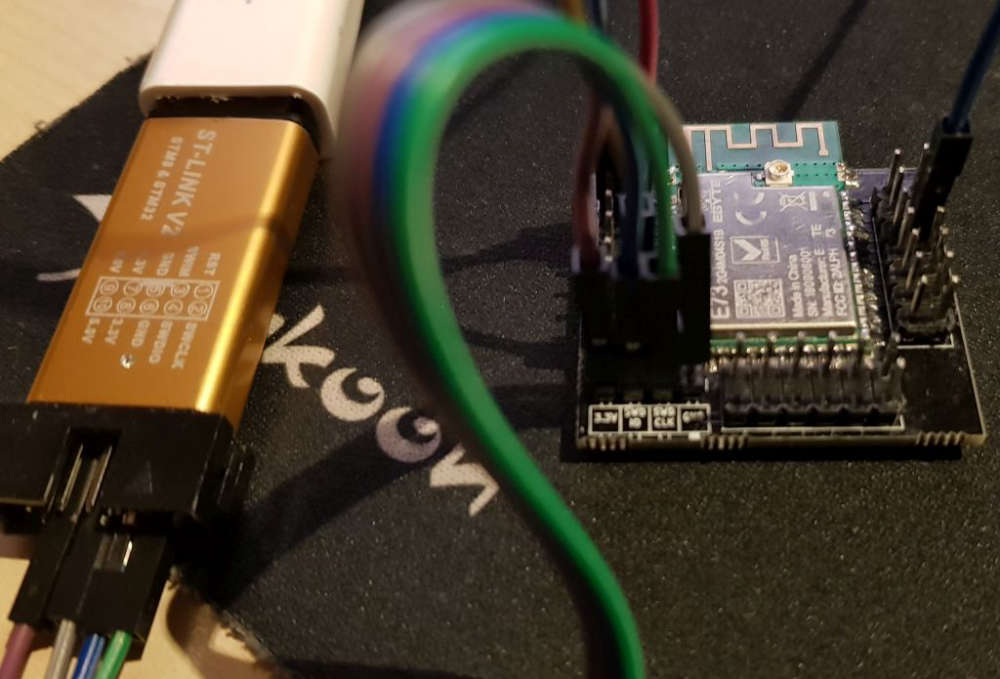
I have tried all kind of driver (using Zadik 2.4), but WInUSB, lisbusbK, libusb ... they all create USB devices only but no COM devices, which Arduino IDE does not "like") only the usbser driver gives me COM devicesand the target device I'm using (which works, when I load the sketch with the ST-Link and select ST-Link in Arduino IDE)
-
@neverdie good discussion, but in order to get my desired solution which is sensor nodes with E-Paper and working with OpenHAB I need I either get the nRF52 modules running with mySensors (ideally just using the Arduino porject and IDE) using the nRF option (I think there is some initial nRF5 support) and using the older nRF24 protocol, or using LoRa with an RFM95 module (which is also supported) or I switch completly to Segger and make a ZigBee V3.0 solution (requiring a ZigBee gateway for OpenHAB). With my new Philips Hue HW version and the new SW firmware upgrade. It is claiming to support ZigBee V3.0 devices which includes also Temp/Hum sensors.
I'm also looking forward for the solution from berkseo where he does exactly that with and nRF52, but that seem to take some time to make it available.
https://www.openhardware.io/view/629/Temperature-and-humidity-sensorverNRF52832E-Ink-display#tabs-instructions