Everything nRF52840
-
Adafruit now has an alpha release nRF52840 offering in a BBC microbit form factor:
https://www.adafruit.com/clue
The listing says it's programmable from the Arduino IDE.
The original micro:bit seems locked in time, with no official mcu upgrades from micro:bit itself, but nonetheless by the end of 2018 over two million micro:bits had been distributed globally. Pretty amazing for such a minimalist, barebones platform.
-
Adafruit now has an alpha release nRF52840 offering in a BBC microbit form factor:
https://www.adafruit.com/clueThe listing says it's programmable from the Arduino IDE.
The original micro:bit seems locked in time, with no official mcu upgrades from micro:bit itself, but nonetheless by the end of 2018 over two million micro:bits had been distributed globally. Pretty amazing for such a minimalist, barebones platform.
-
@NeverDie Ya Adafruit's Clue looks great. I just wish they would have added one more button to the front so up/down/select could be used for a menu system on the display.
@Jon-Raymond said in Everything nRF52840:
@NeverDie Ya Adafruit's Clue looks great. I just wish they would have added one more button to the front so up/down/select could be used for a menu system on the display.
Maybe you could program one of pads #0, #1, or #2 to be a capacitive touch equivalent of the extra button you wish it had?
-
@Jon-Raymond said in Everything nRF52840:
@NeverDie Ya Adafruit's Clue looks great. I just wish they would have added one more button to the front so up/down/select could be used for a menu system on the display.
Maybe you could program one of pads #0, #1, or #2 to be a capacitive touch equivalent of the extra button you wish it had?
@NeverDie Yes that is a good option or use the accelerometer to sense an input.
-
A datasheet for the new nRF5340 is now available: https://infocenter.nordicsemi.com/pdf/nRF5340_OPS_v0.5.1.pdf
It has some improvements, but some of its competition seems to be much lower power.
-
Reading all of this, I think I made a mistake buying the e73-2G4M08S1C and a Deb board. I doubt I have the capabilities to solder this board properly. Since I have no experience designing boards, is there any simple breakout board design available I can order from pcbway so I can at least solder the outer pins?
The only board I found was this one:
https://www.openhardware.io/view/745/Light-and-shock-sensor-or-nRF52840-or-MySensors-or-ZigBee -
@NeverDie doh! I glossed over that one and just assumed it wasn't possible for me due to the pads. Now on 2nd viewing I see that the inner pads are actually through holes, so I can solder them from the other side :-)
Thanks! Has anyone tried that one and has any tips? -
I would also be interested in hearing tips for this type of soldering (thru-hole to pads)
I tried the thru-hole method with the LGA pads on the back of an BT832. It wasn't very successful, I was only able to get one of the 5 holes in my pattern to connect. These look larger and more widely spaced, so it probably works better. -
I would also be interested in hearing tips for this type of soldering (thru-hole to pads)
I tried the thru-hole method with the LGA pads on the back of an BT832. It wasn't very successful, I was only able to get one of the 5 holes in my pattern to connect. These look larger and more widely spaced, so it probably works better.@nagelc Not sure, but here's a guess: maybe generously tinning some braided wire so as to wick up the solder, dipping it in lots of flux, and then feeding it through the hole? Then when you apply heat from a soldering iron hopefully enough of the wicked solder would melt onto the pad to make a connection.
However, I presume the better way would be to apply solder paste on the pads before sticking on the module and then reflow it in an oven.
-
@nagelc Not sure, but here's a guess: maybe generously tinning some braided wire so as to wick up the solder, dipping it in lots of flux, and then feeding it through the hole? Then when you apply heat from a soldering iron hopefully enough of the wicked solder would melt onto the pad to make a connection.
However, I presume the better way would be to apply solder paste on the pads before sticking on the module and then reflow it in an oven.
-
Hi everyone,
I'm a bit a newbie in hardware and need your help. I'm a PHD student and I actually work on ZigBee networks. For a POC, I need to have an hardware device able to capture and send ZigBee messages from a "true" physical device. (An old philips Hue or maybe an Ikea smartbulb for example - normally, 2.4GHz).
The idea is to make a false ZigBee Gateway to work on the secrurity of the enrolment in ZigBee 3.0 within software.
My issue is that I'm unfortunately a bit newbie in on-board programming and thus can't be sure if it's feasible and if it's really complicated or not. I'm posting my message here because the nrf52840 seems to fit my needs with a ZigBee compatibilty.
Thanks by advance for your answers ! -
hello @TruiteCendrée :grin:
yes this is possible with nrf52840, but unfortunately zigbee is not compatible with mysensors. Mysensors is a software stack like zigbee is.
I think you'll get more infos if you take a look on nordic semi forums. They have a zigbee stack for nrf52840.
-
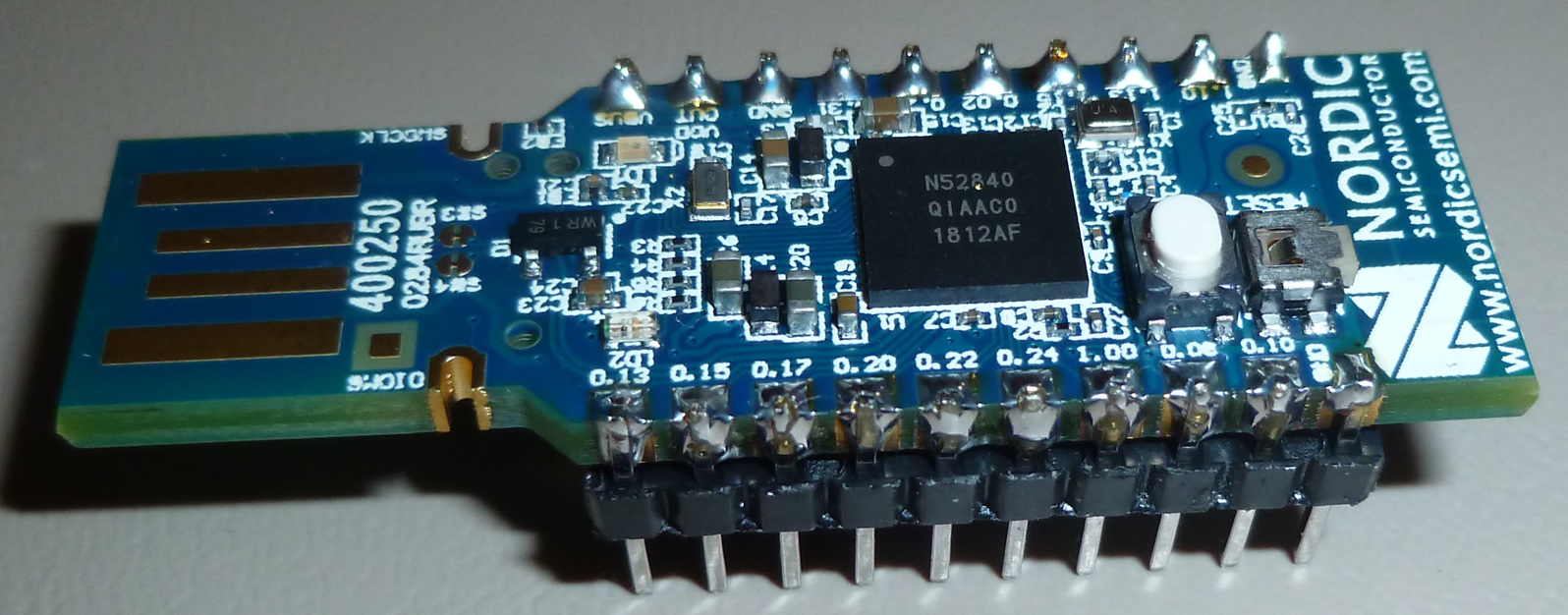
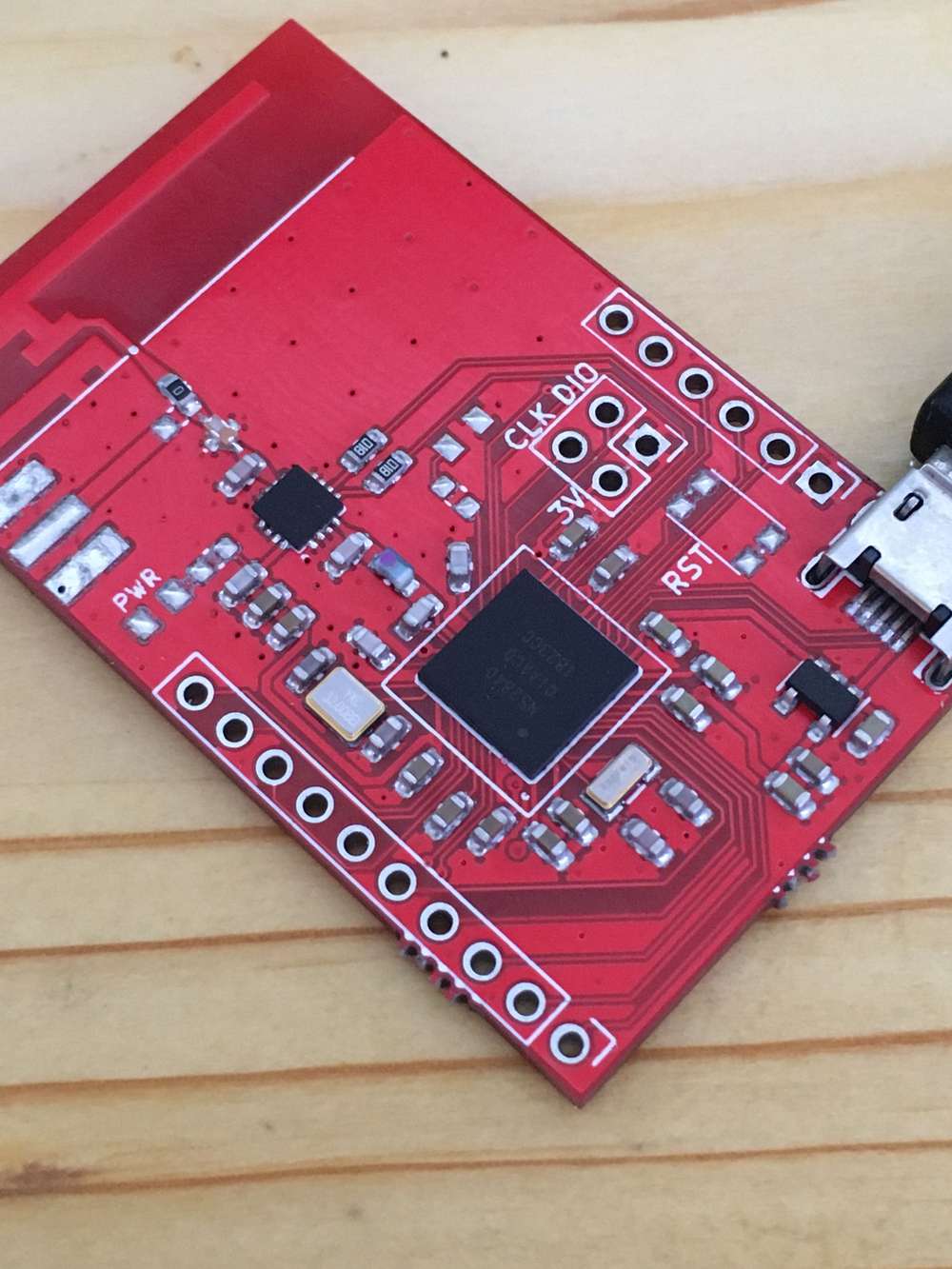
hey guys, i finally assembled my nrf52840 pa board. it was sitting there for quite some time but i couldn't find some spare time to get on with it but here are some experiences i had.
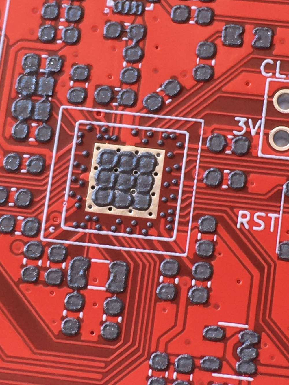
i was worried about this aQFN footprint but it all went well, looks like everything is soldered correctly and i ordered my boards with cheapest HASL instead of ENIG.
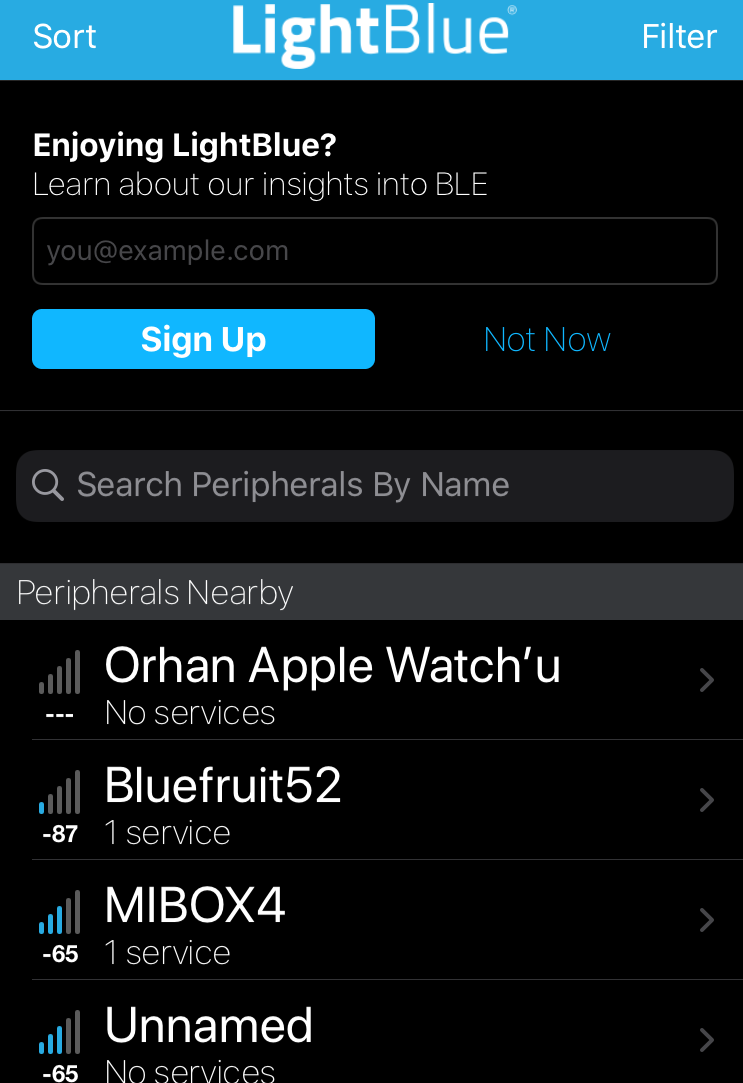
then i uploaded the adafruit feather bootloader to test the bluetooth and it all works ok. i used my iphone 6s as a central device and im not sure if my phone has LNA or PA module inside for bluetooth so it may or may not be better if i use another module like the one i did. this connection is from my module to my phone WITHOUT PA activated at tx power max(8):
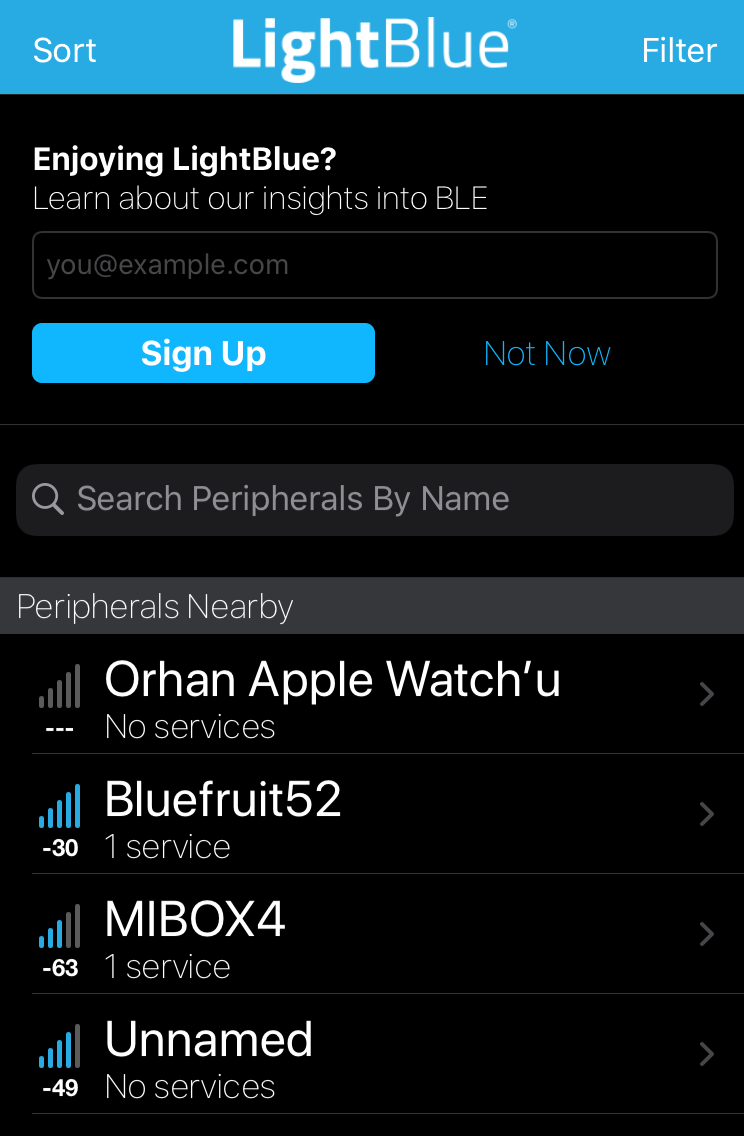
and this is after i activate PA chip on board :
and this is with 3 solid walls in between at around 10 meters distance
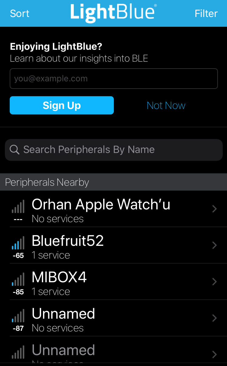
as you can see signal strength is massively different pa bumps up the signal from -87dbm to -30dbm which is probably day and night difference.
but with this setup you manually have to enable and disable rx and tx pins in order to keep the communication. well im not really good at coding but im going to try make the whole thing automatically because nordic already has this PA assist feature buried inside its BLE core, just gotta find a way to make it work.final board, forgot to add i opted to use pcb antenna but i could switch to external antenna as well i just have to reposition the 0 ohm resistor to use that SMA on the side and then results could get even better:
-
hey guys, i finally assembled my nrf52840 pa board. it was sitting there for quite some time but i couldn't find some spare time to get on with it but here are some experiences i had.
i was worried about this aQFN footprint but it all went well, looks like everything is soldered correctly and i ordered my boards with cheapest HASL instead of ENIG.
then i uploaded the adafruit feather bootloader to test the bluetooth and it all works ok. i used my iphone 6s as a central device and im not sure if my phone has LNA or PA module inside for bluetooth so it may or may not be better if i use another module like the one i did. this connection is from my module to my phone WITHOUT PA activated at tx power max(8):
and this is after i activate PA chip on board :
and this is with 3 solid walls in between at around 10 meters distance
as you can see signal strength is massively different pa bumps up the signal from -87dbm to -30dbm which is probably day and night difference.
but with this setup you manually have to enable and disable rx and tx pins in order to keep the communication. well im not really good at coding but im going to try make the whole thing automatically because nordic already has this PA assist feature buried inside its BLE core, just gotta find a way to make it work.final board, forgot to add i opted to use pcb antenna but i could switch to external antenna as well i just have to reposition the 0 ohm resistor to use that SMA on the side and then results could get even better:
-
@NeverDie i had to use stencil because i cant inspect aQFN soc from outside. as you can see every pin is at the bottom of it and they are very tiny. to make sure theres correct amount theres no other way than using stencil. to be honest i was expecting problems but it was ok :)
-
after abit of looking around and testing i think i made it work at least examples are quite responsive without a single disconnect. i had to add some header files and extra bit of code to every sketch so the knows how to use PA/LNA.
static void pa_lna_assist(uint32_t gpio_pa_pin, uint32_t gpio_lna_pin)
{
    ret_code_t err_code;

    static const uint32_t gpio_toggle_ch = 0;
    static const uint32_t ppi_set_ch = 0;
    static const uint32_t ppi_clr_ch = 1;

    // Configure SoftDevice PA/LNA assist
    ble_opt_t opt;
    memset(&opt, 0, sizeof(ble_opt_t));
    // Common PA/LNA config
    opt.common_opt.pa_lna.gpiote_ch_id  = gpio_toggle_ch;        // GPIOTE channel
    opt.common_opt.pa_lna.ppi_ch_id_clr = ppi_clr_ch;            // PPI channel for pin clearing
    opt.common_opt.pa_lna.ppi_ch_id_set = ppi_set_ch;            // PPI channel for pin setting
    // PA config
    opt.common_opt.pa_lna.pa_cfg.active_high = 1;                // Set the pin to be active high
    opt.common_opt.pa_lna.pa_cfg.enable      = 1;                // Enable toggling
    opt.common_opt.pa_lna.pa_cfg.gpio_pin    = gpio_pa_pin;      // The GPIO pin to toggle

    // LNA config
    opt.common_opt.pa_lna.lna_cfg.active_high  = 1;              // Set the pin to be active high
    opt.common_opt.pa_lna.lna_cfg.enable       = 1;              // Enable toggling
    opt.common_opt.pa_lna.lna_cfg.gpio_pin     = gpio_lna_pin;   // The GPIO pin to toggle

    err_code = sd_ble_opt_set(BLE_COMMON_OPT_PA_LNA, &opt);

}
in this form i like the ble, without pa not so much. theres just big down side which is nrf52840 definitely not hobbyist friendly. next time i may design a quick nrf52832 pa board (this one has regular QFN package) to test with the same setup and compare the results.
-
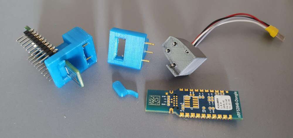
@NeverDie , indeed OTA is optimal, then at least the default pre-flashed bootloaded is not so bad to be able to update SW without debugger. But for development purposes the USB dongles are much cheaper than the devkit, yet lacking debug connections. I hope this pogo pin adapter can help others, as I use it to flash and even debug with Ozone on that cheap nRF52840 USB dongle.
Link to CAD Model : https://a360.co/3jr91PD
Also on thingiverse although thingiverse connection is not stable
https://www.thingiverse.com/thing:3384693I also like platformio Arduino and would like to have the nRF52840 USB dongle supported without the softdevices, as they prevent the direct usage of the RF peripheral for custom radio.