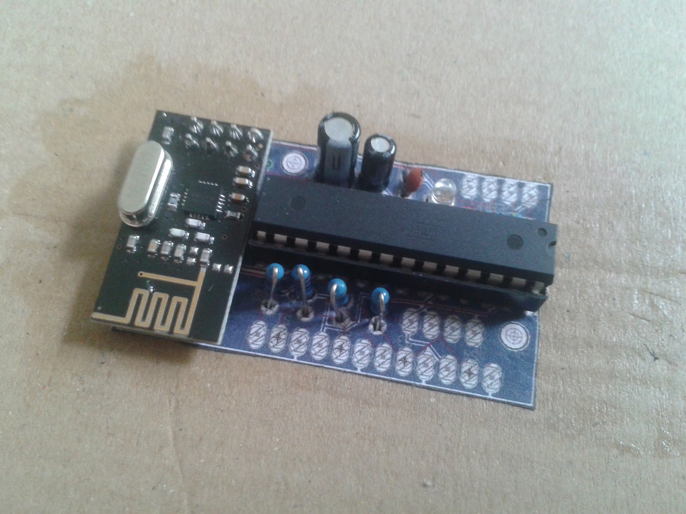
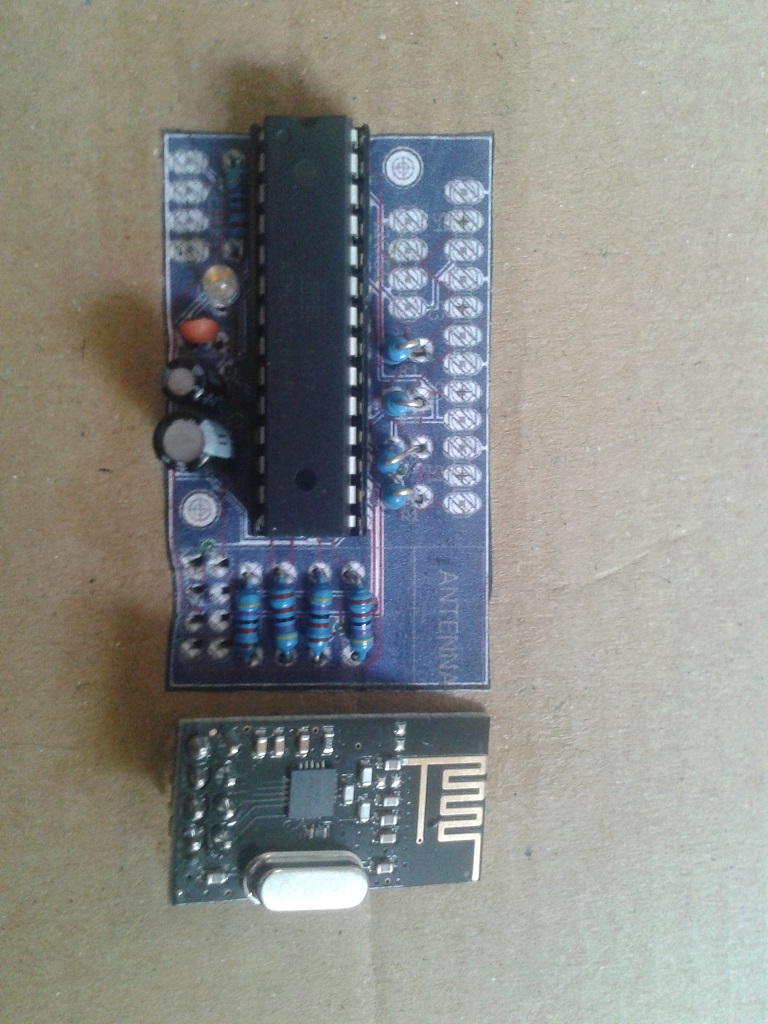
Hi Gert,
thx for your feedback. Lets make a small structure to discuss the things:
Battery-monitoring
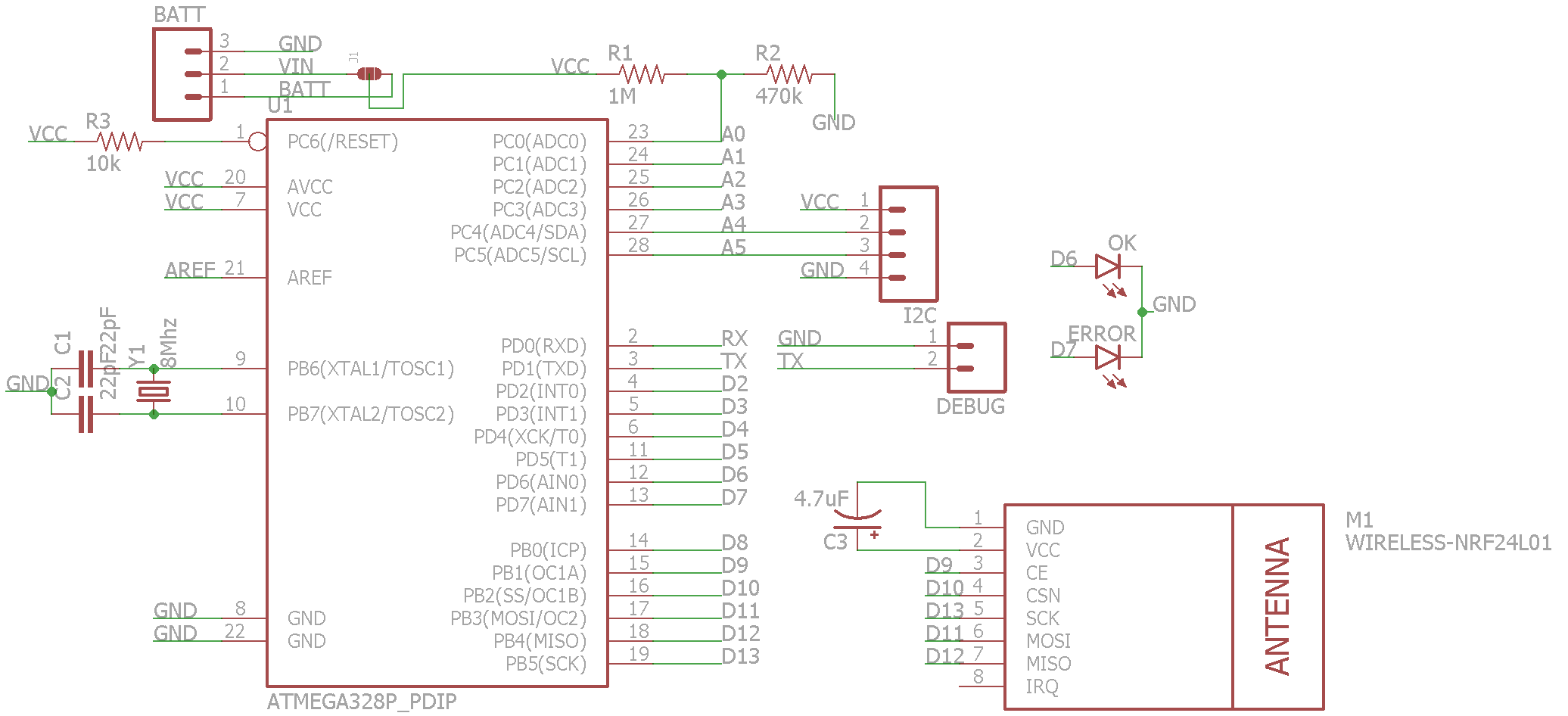
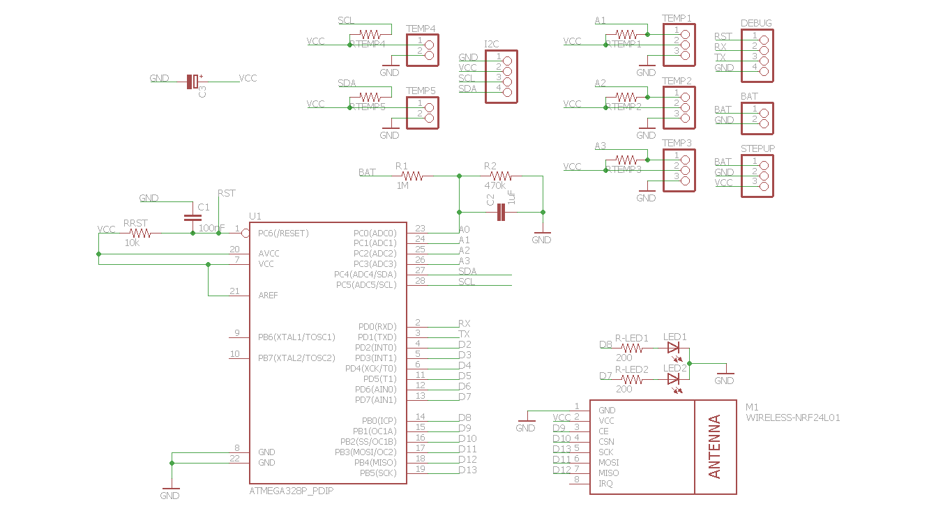
I plan to you use the AREF as 3.3v Reference powered by the step-up-module. I think most of my sensors will have a step up. So this should be quite easy and accurate. In this case i solder a wire instead of R1 and "unsolder" R2....
OR (if i really want) i can use the voltage divider on A0 instead (like mysensors.org says). I think with this schematics i have both possibilities... How does it work without resistors and internal vref (1.1v)? I only saw the version with 2 resistors on the mysensors page.
By the way: I tested 3 step-up-modules:
Pololu with NCP1402
Sparkfun with NCP1402
"China-Module"
The China-Module is crap (+-240uA).
Pololu draws +-100uA in sleep mode
The Sparkfunboard only draws +-30uA in Sleep mode. I will go for that.
Capacitors:
There is a capacitor between VCC and GND. The capa between AVCC and GND is missing, you're right. Thx.
I want to use AREF, so i cannot pull it to ground. Or what did you mean? Or am i missunderstanding something? I thougt AVCC is the supply voltage for the "REF"-function. And AREF is the reference-voltage....
Programming
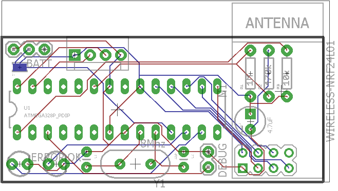
In an updated version from last night, i moved the debugport to the topboard. I can upload new sketches via RX/TX...
Do you know if it is possible to use the ISP when the NRF24l01+ is still connected to these pins?
LED
I dont want to have a regular LED-blink (power consumption). It shall only blink when working(transmitting).
Green => All OK: Measures are ok, packet was sent
RED => ERROR: Measurement fails or packet could not be sent...
A DUOled would save some space, but no pins.
Sensors
I think i will have a max of 5 Sensors connected on one board , so there is no need to save pins whereever i can.
The I2C port is like the sparkfun "standard" ;) I have a lot of HTU21D-BOBs laying around. They work like a charm
After i gave my child something to eat, i update and upload the schematics...give me some time ;)

