Navigation

    • Register
    • Login
    • OpenHardware.io
    • Categories
    • Recent
    • Tags
    • Popular
    1. Home
    2. ben999
    3. Posts
    • Profile
    • Following
    • Followers
    • Topics
    • Posts
    • Best
    • Groups

    Posts made by ben999

    • IP phone and beacon

      Hi guys

      Long time no speak but still a MySensors fan !!

      My new project is a bit tougher than expected.

      Here is the thing: landline phones used to be analog type, with some 40v running across the wires... adding a beacon for noisy environment was a breeze, just plug it in and whenever a call comes in the beacon picks the signal and rings.

      My country has now moved to digital signal, IP i would say (please correct me if wrong terminology).
      So now the phone is connected at the back of optic fiber internet box (modem) via RJ45 plug.

      Needless to say that analog beacon has become useless. Beacon manufacturers have not yet moved their tech towards IP protocol.

      Have you ever bumped into that kind of challenge ? ๐Ÿ˜

      I have a spare W5100 in the drawer... would it be able to access to the phone data, to check whether it's ringing ?

      Hope you get the picture and you can show me the way forward ๐Ÿ‘

      posted in General Discussion
      ben999
      ben999
    • RE: openHAB 4 MySensors Binding

      @niccodemi I am no expert and am having a tough time with these files as well !!!

      My .things file looks like so :

      Bridge mqtt:broker:mosquitto "MySensorsGateway"@"Home" [host="openhabian", port="1883", secure=false]
      {
      	Thing topic garageDoor01 "Garage"@"Basement" {
      		Channels:
      			Type contact :	garageDoor01switch	[stateTopic="mysensors-out/19/1/1/0/16", transformationPattern="MAP:contact.map"]
      			Type datetime : garageDoor01switch_LastUpdate
      	}
      

      As far as i understand, you're missing that "linktopic" descrption...

      posted in OpenHAB
      ben999
      ben999
    • RE: openHAB 4 MySensors Binding

      Hi @zkarolyi

      I can not provide any help on that matter as i went the MQTT way.

      The binding for serial gateway requires loads of work from the MySensors dev team; so it might tatke a while before it becomes available (if it does all together). I really appreciate all the effort put into this but i also understand that it might come to an end someday. No matter how much i prefer the serial gateway over MQTT... i ended up in the mqtt team

      Back to your issu : the jar file might not be compatible with OH4

      posted in OpenHAB
      ben999
      ben999
    • RE: openHAB 4 MySensors Binding

      @mfalkvidd Genius !!! ๐Ÿ˜ฎ

      posted in OpenHAB
      ben999
      ben999
    • openHAB 4 MySensors Binding

      Hello there
      I thought it would be a good idea to upgrade my system to openHAB4, as i wanted to play with my security cameras linked to a Synology NAS system...
      Well it didn't go according to plan.
      First openhabian had to be upgraded from Buster to Bullseye in order to get Java from 11 to 17. Then Java got upgraded, By that time MySensors stopped working. So i started over with a fresh install of MySensors. All went well until

      make
      
      hal/architecture/Linux/drivers/core/GPIO.cpp: In constructor โ€˜GPIOClass::GPIOClass()โ€™:
      hal/architecture/Linux/drivers/core/GPIO.cpp:53:50: warning: โ€˜%sโ€™ directive output may be truncated writing up to 255 bytes into a region of size 48 [-Wformat-truncation=]
         53 |    snprintf(file, sizeof(file), "/sys/class/gpio/%s/base", de->d_name);
            |                                                  ^~
      hal/architecture/Linux/drivers/core/GPIO.cpp:53:12: note: โ€˜snprintfโ€™ output between 22 and 277 bytes into a destination of size 64
         53 |    snprintf(file, sizeof(file), "/sys/class/gpio/%s/base", de->d_name);
            |    ~~~~~~~~^~~~~~~~~~~~~~~~~~~~~~~~~~~~~~~~~~~~~~~~~~~~~~~~~~~~~~~~~~~
      hal/architecture/Linux/drivers/core/GPIO.cpp:62:50: warning: โ€˜%sโ€™ directive output may be truncated writing up to 255 bytes into a region of size 48 [-Wformat-truncation=]
         62 |    snprintf(file, sizeof(file), "/sys/class/gpio/%s/ngpio", de->d_name);
            |                                                  ^~
      hal/architecture/Linux/drivers/core/GPIO.cpp:62:12: note: โ€˜snprintfโ€™ output between 23 and 278 bytes into a destination of size 64
         62 |    snprintf(file, sizeof(file), "/sys/class/gpio/%s/ngpio", de->d_name);
            |    ~~~~~~~~^~~~~~~~~~~~~~~~~~~~~~~~~~~~~~~~~~~~~~~~~~~~~~~~~~~~~~~~~~~~
      g++ -MT build/hal/architecture/Linux/drivers/core/interrupt.o -MMD -MP -march=armv8-a+crc -mtune=cortex-a53 -mfpu=neon-fp-armv8 -mfloat-abi=hard -DMY_RADIO_RF24 -DMY_GATEWAY_LINUX -DMY_GATEWAY_MQTT_CLIENT -DMY_DEBUG -DLINUX_SPI_BCM -DLINUX_ARCH_RASPBERRYPI -DMY_MQTT_CLIENT_ID=\"impassedesroses\" -DMY_MQTT_SUBSCRIBE_TOPIC_PREFIX=\"mysensors-in\" -DMY_MQTT_PUBLISH_TOPIC_PREFIX=\"mysensors-out\" -DMY_RF24_PA_LEVEL=RF24_PA_LOW -DMY_CONTROLLER_IP_ADDRESS=127,0,0,1  -Ofast -g -Wall -Wextra -std=c++11 -I. -I./core -I./hal/architecture/Linux/drivers/core -I./hal/architecture/Linux/drivers/BCM -c hal/architecture/Linux/drivers/core/interrupt.cpp -o build/hal/architecture/Linux/drivers/core/interrupt.o
      hal/architecture/Linux/drivers/core/interrupt.cpp:33:10: fatal error: stropts.h: No such file or directory
         33 | #include <stropts.h>
            |          ^~~~~~~~~~~
      compilation terminated.
      make: *** [Makefile:99: build/hal/architecture/Linux/drivers/core/interrupt.o] Error 1


      Please advise if i should start over from the very begenning (fresh SD) or just stick with openHAB 3 (but soon or later it will be superseeded)

      Thanks a lot for your time people.

      posted in OpenHAB
      ben999
      ben999
    • RE: Microwave oven (no kidding :D)

      @skywatch great, thanks a lot for your suggestion. A bit of research on the internet educated me about these diodes ๐Ÿ˜„ looks like they already exist on the board that carries the relay. However, i deeply thank you for the info. This forum and internet in general is such a powerful tool ๐Ÿ‘

      @ejlane your concern is fully justified ๐Ÿ‘ i also come from an engineering background and i like to think "worse case scenario".
      The more one look the more one find that the very vast majority or microwave ovens work the same way : there are 3 industrial switches built in the door lock. 2 of them are cabled on the "power side", one is for signaling ("software side"). So we are pretty safe on that matter.
      But you are so right about safety. Magnetron do emitt dangerous waves and capacitors and stuff packed in the oven can be deadly because of high voltage.

      Thanks both for suggestions. I will come back with updated sketches and beg for advice once more ๐Ÿ˜‰

      posted in Hardware
      ben999
      ben999
    • Microwave oven (no kidding :D)

      Hi guys,

      My microwave oven broke down last month.

      Not only it's a pain in the backside but it is also more waste for the planet.

      A quick search on the internet educated me about safety and how to test parts.

      Turns out the main board is dead (display works fine, most buttons too but "start" and "stop" buttons are useless).

      New motherboard is difficult to source and is no more available from manufacturer (i bought it 2 years ago but must have been some fairly old design... ๐Ÿ™„ )

      So back to drawing board and soldering iron:

      • arduino nano
      • 2.8" TFT colour display
      • rotary encoder
      • salvage "power board" from microwave (gives 12V and 5V)

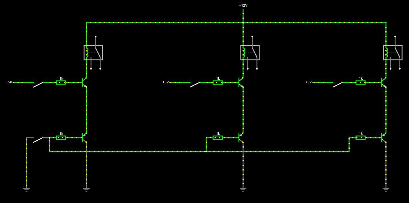
      I am pretty well on my way design-wise and need a final advice on transistors ; following are 2 arrangements regarding what i would call the "oven door transistor" (the bottom PNP one).
      The 3 NPN transistors at the top drive a relay each one (magnetron, plate and heating resistance). Each transistor is driven by the arduino via a resistor.

      Please accept my apologies if any of my sketches make your eyes bleed. ๐Ÿ˜

      Which one would be the least bad and how could it be improved.

      Thanks a lot for reading ๐Ÿ‘

      EDIT: Sketches drawn with https://www.falstad.com
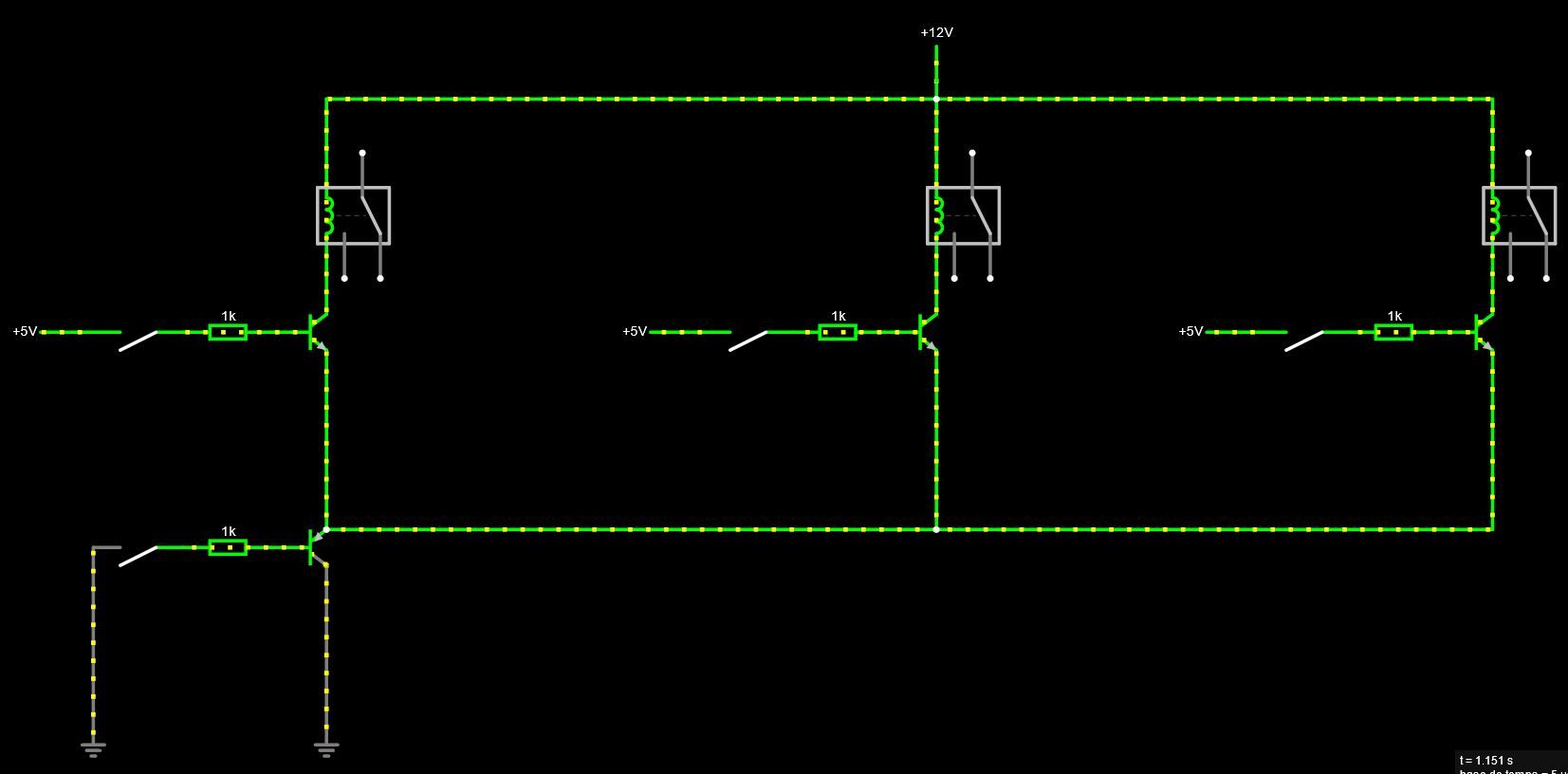
      1.JPG

      2.JPG

      posted in Hardware
      ben999
      ben999
    • RE: MQTT losing messages...

      @JeeLet
      @OldSurferDude

      Thank you both ๐Ÿ‘

      My Raspberry 3 does it all :

      • gateway with nrf24 module (standard one)
      • mysensors MQTT gateway
      • Mosquitto broker

      MQTT Explorer has been installed on my fav laptop and it helps seeing clearer.

      Nevertheless i cannot reproduce the errors.

      I have multiple points of view:

      • node : using arduino ide serial monitor
      • mysensors gateway: using tail log in a terminal window
      • openHab : using tail log in an internet explorer window
      • MQTT explorer : in its own window

      I can sent MQTT messages from different devices :

      • iOS openhab from my phone
      • openhab (basic UI) from an internet explorer window
      • MQTT explorer (messages can be made-up, very cool tool)
      • terminal window (linux laptop via ssh)

      The less reliable way of sending MQTT message is via terminal : after 2 to 10 succesfull messages it then stops working. At first, node receives messages and processes them (servo moves). But after a few messages, node doesn't receive anymore. MQTT Explorer shows the change of state of the topic but message doesn't go anyfurther... no other monitor show a change.

      @OldSurferDude i'm not sure i understand

      Each node should be sending messages to its own topic.

      Can the mysensor gateway subscribe to more than one topic (which is mysensors-in at the mo) ?

      Thanks a lot for helping me through ๐Ÿ˜Š

      posted in OpenHAB
      ben999
      ben999
    • RE: MQTT losing messages...

      @JeeLet thanks a lot for your message

      You're right :

      • openhab 3
      • Raspberry Pi 3 MQTT gateway with Mosquitto
      • arduino nodes
      • nRF24 network

      TBH i don't know where to start, so difficult to point a finger...

      posted in OpenHAB
      ben999
      ben999
    • MQTT losing messages...

      Hi guys,

      Long story cut short :

      I've had lots of "temporary gone bad nodes" since migrating from serial to mqtt.

      Nodes that are normally working fine but then stop responding (most annoying being the one driving the garage door motor ๐Ÿ˜ฑ i now keep a key anytime with me instead of just relying on openHab...). A reboot cures it.

      So i decided to design a simple logger with arduino + sd card + rtc.

      Beside that i am also designing an automatic cat flap locking node, so cats dont go out at night. As i dont want any rtc on that node, i rely on time supplied by controller with requestTime(). So here i am trying to understand how to send that request to controller via mqtt by sending publications...

      That's how i discovered that many publications are lost.

      What do you suggest to investigate further ? I might have reached my limits... ๐Ÿ˜ฌ some help would be welcome ๐Ÿ‘

      Thanks a lot ๐Ÿ˜Š

      posted in OpenHAB
      ben999
      ben999
    • RE: nrf24+ module with stick antenna

      @skywatch oh great ๐Ÿ‘ thanks for that !

      by removing the smd then the signal becomes "compatible" with a 2.4ghz stick antenna ?

      or shall i go with wire and adjust length ?

      Thanks everyone ๐Ÿ™‚

      posted in Hardware
      ben999
      ben999
    • RE: nrf24+ module with stick antenna

      @NeverDie thanks a lot for taking so much time for your answer ๐Ÿ‘

      Your explainations pushed my thinking a bit further. I now understand that i can't just solder a 2.4ghz stick antenna in-lieu of a "trace" antenna just because it is a 2.4ghz board... am i right ?

      The main reason for my post is that i need to have a remote antenna.
      And i also wanted to keep clear of Power Amplified modules as their power consumption is too high for my needs (tiny LiPo and solr panel)

      And i also wanted to use what's in the drawer ๐Ÿ˜‰

      I shall then turn to nrf modules with external antenna. Usual one are difficult to get now. But it seems there are newer ones out there (at least their layout seems new to me) :

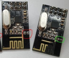
      nrf.JPG

      Anyone tried yet ?

      Anyway, thanks a lot for making things clearer ๐Ÿ˜Š

      posted in Hardware
      ben999
      ben999
    • nrf24+ module with stick antenna

      Hi Guys,

      I would like to connect a stick antenna to a basic nrf24L01+ module.

      Please note that i do not need any additional range.

      The reason i'm asking is because the nrf is surrounded by metal, copper traces and battery...

      So getting the antenna out of the housing might help.

      I have an SMA connector handy and a stick antenna as well.

      My main question is about soldering the coax cable :

      hack.JPG

      1 -shall i cut the trace as stated in numerous hacksites ?
      2 - shall i solder the inner conductor where the blue arrow is ?
      3 - shall i solder the outer connector (shield?) where the red arrow is ? or is it best to scratch underside of board and solder straight into ground plane ? but then that reveals more inner connector length, thus next question...

      What is the importance of the length of "naked" inner conductor where the insulation will be cut ?

      Thanks a lot for your help, comments of any sort are welcome ๐Ÿ˜‰

      posted in Hardware
      ben999
      ben999
    • RE: Smart doorbell

      @adamf663 sorry for delay! I am focusing on mostly software at the moment. So nothing to show so far ๐Ÿ˜‰ i'll be posting as soon as the project moves forward again ๐Ÿ‘ please read on !!!

      @MasMat thanks a lot for your suggestions. As suggested first it is more than probably a case of rights/permissions.

      There are many ways to launch a script at startup but in my case some deamons were started via "root" and some others via "user".
      As stated before, all worked perfectly when logged under "user" (pi).
      So, to summarise:

      • rc.local didn't work
      • crontab didn't work
      • .bashrc didn't work
        These might work in the end but i'm not brainy enought to get to it.

      Then came "systemctl" !
      First create a .service file

      $ sudo nano  /etc/systemd/system/doorbell.service
      
      [Unit]
      Description=My test service
      After=multi-user.target
      [Service]
      Type=simple
      Restart=always
      ExecStart=/usr/bin/python /home/pi/doorbell02.py
      [Install]
      WantedBy=multi-user.target
      #WantedBy=default.target    -> test this if previous doesn't work
      

      Reload all daemons to check if your new .service file is ok
      Then allow your new service file to be loaded at boot
      Last, check if loading worked. If status returns "active" then it's a win ๐Ÿ‘

      $ sudo systemctl daemon-reload
      $ sudo systemctl --user enable doorbell.service
      $ sudo systemctl --user start doorbell.service
      $ systemctl --user is-active doorbell.service
      

      Last step: systemctl loads these services at loggin by default (as in : enter user and password). I need it to start automaticaly with no human input. systelctl offers a way to load services without loggin for a given user :

      $ loginctl user-status pi
      

      Check status with

      $ loginctl user-status pi
      

      If status returns "linger: yes" then it's (once again) a win ๐Ÿ‘

      Thanks again @MasMat for suggesting paths to investigate

      That's it for now, i'll be back on the hardware point of view next time !

      posted in My Project
      ben999
      ben999
    • RE: Smart doorbell

      Hi @MasMat

      Thanks a lot for your suggestions ! You DO talk like a linux ninja though ๐Ÿ˜„

      I'll have a go at these ๐Ÿ‘

      First let's try to understand :

      -fstab has multiple credentials currently

      what do you mean and how does this affect my "share"? I am very eager to understand. (although this part of my project is doing fine)

      did you have multiple pythons? (bbt.py, doorbell.py?)

      Sorry, no. My mistake. I tried to sanitise that post and forgot some dirt ๐Ÿ˜‰ only "doorbell.py running. Initial message corrected now.

      the launcher I believe has unnecessary lines (the changing directories)

      Ok i'll get that cleaned up

      crontab: why do "sudo crontab -e"? Would using just "crontab -e" use pi-users crontab and have less conflicting permissions?

      Ok i'll have a go as well, it makes sense. Trouble is i tend to put "sudo" everywhere so it kinda "forces" things to go as i planned them... not necessarily clever i agree... ๐Ÿ˜•

      I let you know tonight

      Would you have a suggestion on how to debug this script running in the background ? I tried pdb but it messes things up (starts multiple instances of doorbell.py... camera is constantly taking pictures, whole thing goes crazy) There must be some log of some sort that gets error message from programs running in background ?

      Thank you ever so much for spending time here. I'm really stuck now (been 2 weeks) and i really appreciate your effort here ๐Ÿ‘

      posted in My Project
      ben999
      ben999
    • RE: Smart doorbell

      My openhab is setup via files.

      I had some hard time discovering MQTT which was new to me and setging up openhab as it changed quite a lot since version 2.

      So here are my files, gin case it might help someone sometime :

      "items" file :

      Switch		doorBell01state	"Door Bell"              <alarm>	 {channel="mqtt:topic:mosquitto:doorBell01:doorBell01state"}
      

      "things" file :

      Bridge mqtt:broker:mosquitto "MySensorsGateway"@"Home" [host="192.168.1.20", port="1883", secure=false]
      {
      Thing topic doorBell01 "Door Bell"@"Front Gate" {
                      Channels:
                              Type switch :   doorBell01state         [stateTopic="doorbell/50/1/0/0/1", transformationPattern="MAP:onoff.map"]
              }
      }
      

      "rules" file :

      rule "frontgate bell ringing"
      when
               Item doorBell01state changed to ON
      then
              sendBroadcastNotification("Someone ringing at da gate!")
      end
      

      "map" file : (needed because i cant cope with types, numbers, decimals, values, ... so i tried many tricks and that one worked)

      0=OFF
      1=ON
      
      posted in My Project
      ben999
      ben999
    • Smart doorbell

      Hello World ๐Ÿ˜‰

      Here is my latest project, near completion: smart doorbell.

      Old raspberry 1B connected to the regular RaspiCam V1 and a push button.

      As soon as pushbutton is pressed :

      • RPi sends an MQTT message to network
      • Cam takes a picture and stores it to my local NAS
      • Gateway sends a notification all my portable devices connected to openHAB
      • RPi sends and email with picture attached

      This post has 2 goals :

      • share my findings. My house was until now still relying on openhab2 and mysensors binding. All working very happily. But there was no direct answer to get a raspberry to behave as a MySensor device and talk directly to the gateway. It was also time to move to openhab3. I was then advised to have a go at MQTT. So be it !!!
      • get some help linux-wise for completion of this project.

      I had to learn new tricks along the way... like mounting a network drive to the RPi. It's kind of linking/sharing a folder between my NAS and my RPi. If a file is dropped into that "mounted folder" it then appears on each device. Magic ๐Ÿ‘
      To do so edit your fstab file

      $ sudo nano /etc/fstab
      

      and add something like :

       //192.168.1.77/home/DoorBell     /home/pi/doorbell/ cifs vers=2.0,username=username,   password=passwordthatgoeswithit,credentials=/home/pi/doorbell .smbcred,noauto,x-systemd.automount 0 0
      

      I have tested this setup both at work and at home. I had to remove "credentials" and everything after at home as i could never get it to work (got some errors). I also had to change from "vers=3.0" to "vers=2.0". Googling never got me a real explanation...

      This is my python script, working as it should :

      import os
      import subprocess
      from datetime import datetime
      from gpiozero import Button
      
      button = Button(17)
      
      while True:
              button.wait_for_press()
              os.system('mosquitto_pub -h openhabian -t doorbell/50/1/0/0/1 -m "1"')
              time = datetime.now()
              filename = "capture-%04d%02d%02d-%02d%02d%02d.jpg" % (time.year, time.month, time.day, time.hour, time.minute, time.second)
              subprocess.call("raspistill -t 500 -o %s" % filename, shell=True)
      	subprocess.call("echo '' | mutt -s 'Someone ringing !' -i messageBody.txt myemailaddress@someprovider.com -a %s" % filename, shell=True)
              os.system('sudo /home/pi/movefile.sh')
              os.system('mosquitto_pub -h openhabian -t doorbell/50/1/0/0/1 -m "0"')
      

      The picture is stored with a convenient name (date and time) like so : capture-20210910-224322.jpg
      mutt is some simple, cool and efficient mailing program.
      messageBody.txt is a plain text file containing the body of the generic email.
      movefile.sh is a script that moves the jpg file from RPi's SD card up to NAS shared folder once the email has been sent.

      As i said previously it's all working as intended with

      $ python doorbell.py
      

      Next step is to get that python script to be launched at startup. A job for cron:

      $ sudo nano launcher.sh
      
      	#!/bin/sh
      	# launcher.sh
      	# navigate to home directory, then to this directory, then execute python script, then back home
      	cd /
      	cd home/pi
      	sudo python doorbell.py
      	cd /
      
      $ chmod 755 launcher.sh
      $ sh launcher.sh
      $ mkdir logs
      $ sudo crontab -e
      

      add this to file :

      @reboot sh /home/pi/launcher.sh >/home/pi/logs/cronlog 2>&1
      
      $ sudo reboot
      

      Quick check at logfile to make sure it all went well:

      $ cat logs/cronlog
      

      From then the email part of my script doesn't work anymore.
      Trouble with rights ?

      ps aux
      

      returns that launcher.sh belongs to root but python script belongs to pi :

      root       475  0.0  0.0      0     0 ?        S    16:51   0:00 [cifsd]
      root       500  0.0  0.6   7932  2300 ?        Ss   16:51   0:00 /usr/sbin/cron -f
      root       502  0.0  0.6   9452  2384 ?        S    16:51   0:00 /usr/sbin/CRON -f
      root       506  0.0  0.3   1924  1148 ?        Ss   16:51   0:00 /bin/sh -c sh /home/pi/launcher.sh >/home/pi/logs/cronlog 2>&1
      root       511  0.0  0.2   1924  1108 ?        S    16:51   0:00 sh /home/pi/launcher.sh
      root       513  1.5  2.5  34348  9728 ?        Sl   16:51   4:25 python doorbell02.py
      root       514  0.0  0.3  27640  1364 ?        SLsl 16:51   0:00 /usr/sbin/rngd -r /dev/hwrng
      root       525  0.0  0.4   4292  1588 tty1     Ss+  16:51   0:00 /sbin/agetty -o -p -- \u --noclear tty1 linux
      root       527  0.0  0.4   6600  1852 ?        Ss+  16:51   0:00 /sbin/agetty -o -p -- \u --keep-baud 115200,38400,9600 ttyAMA0 vt220
      root       757  0.0  1.6  12224  6228 ?        Ss   16:53   0:00 sshd: pi [priv]
      pi         760  0.0  1.8  14584  7072 ?        Ss   16:53   0:00 /lib/systemd/systemd --user
      

      Does it ring a bell to anyone ?

      Thanks a lot for your help guys!

      posted in My Project
      ben999
      ben999
    • RE: Raspberry as a node (bis)

      @Yveaux ๐Ÿ‘ thank you

      ๐Ÿ˜„ here you are talking once again a weired language ๐Ÿ˜„

      Ok i'll dig what MQTT can do for me. How does the piece of data (someone pushed the doorbell button) gets from RPi to openhab ? Does it stay local within the LAN (and gets directly to my gateway) or does it have to travel through internet up to openhab and down again to my gateway (remember, my bell has to ring) ?

      So last question just to be sure : it is not common practice to use RPi as a node ? And there is no "sketch" ready made that can be tweaked ?

      Thanks a lot for your time, i really appreciate it ๐Ÿ˜‰

      posted in Hardware
      ben999
      ben999
    • RE: Raspberry as a node (bis)

      @Yveaux hi

      Thanks a lot for your reply ๐Ÿ‘

      Slight misunderstanding here ๐Ÿ˜‰

      Raspberry will be connected to LAN to transfer picture to NAS, probaly via wifi (or wired if i decide to go down the PoE road...)

      But i also want the RPi to be connected to openHab in order to send notification of "front gate button pushed" via MySensors so i can get the doorbell to ring AND a broadcast message from openHab.

      About security:
      My router offers me an option of NOT giving internet access to any device while still being connected to LAN. Is that safe enough ?

      posted in Hardware
      ben999
      ben999
    • Raspberry as a node (bis)

      Hi all

      Not posting doesn't that mean i've lost interest ๐Ÿ˜

      My house relies more and more on MySensors and openHab... great team, i'm delighted !

      Time for a new challenge : "smart" door bell.

      What is on my mind : old raspberry with its cam hidden in the front fence pillar. As soon as the doorbell push button is pushed, the bell rings (inside the house) but also a picture is taken and (at the beginning at least) is stored onto my local NAS. Then, if i'm not home i would get a broadcast message from OH.

      That brings me to the following question : can a Raspberry Pi be hooked to a NRF module and behave like a node ?

      That post (https://forum.mysensors.org/topic/6949/raspberry-pi-zero-as-sensor-node) brought me a security issue : smart devices connected to LAN can become a weakness

      Other than that i would connect an Arduino to the RPi but then that looks a bit over-complicated...

      Thanks for your help people ! ๐Ÿ‘

      posted in Hardware
      ben999
      ben999
    • RE: Piezzo siren/alarm

      @fotofieber DC+ one output is really poor and voltage has no impact on noise. I have tested with up to 6S LiPo and there's absolutely no gain as compared to 5V DC

      AC+ two outputs is a game changer! Much louder right from +/-5V and really a killer @ +/-12V.

      So that's it: the first iteration of this project will go for a step-up converter from 5V up to 12V for the piezo speaker.

      Thanks folks!

      EDIT: could someone suggest a MOSFET (or transistor) that could be used in lieu of the huge (and probably over-sized) TIP120 (that where there, waiting in the drawer ๐Ÿ™‚ ). Through-hole is my league. SMD is a bit of a struggle (welding, machining pcb, ...)

      Thanks again ๐Ÿ˜ƒ

      posted in Hardware
      ben999
      ben999
    • RE: Piezzo siren/alarm

      @fotofieber gosh that a good analysis ๐Ÿ‘ that makes a lot of sense
      Then i can picture things better:

      • one output with 0 et +5V is considered as DC
      • two output pulling differentially -5V to +5V... looks like a sin curbe... so it's AC !

      Breadboard is out and still cabled, i'll have a go asap and confirm

      Thanks again for your knowledge

      posted in Hardware
      ben999
      ben999
    • RE: Piezzo siren/alarm

      Guys,

      Thanks all a lot for your input.

      Seems sorted :

      • differential drive (ToneAC)
      • transistor (TIP120 in my case, not sure it's my best move)
      • 3S louder than 2S, itself louder than 1S

      Schematic TIP120 and 1k resistors

      0_1555413823315_Capture.JPG
      I did also put a 1k resistor in between the piezo speaker pins... but it lowered the tone by quite a lot... ๐Ÿค”

      To be tested

      I'll have a go with an inductance to see what " then you double the swing" means... double the loudness or double the speed ?

      Thanks again, people involved ๐Ÿ˜‰

      posted in Hardware
      ben999
      ben999
    • RE: Piezzo siren/alarm

      @fotofieber ๐Ÿ˜ oh yes i got that one correct ๐Ÿ˜œ

      It was more about how to size the inductor and stuff. Guys on these forums know their sh*t, they dont go into much details: "just stick a thing there and you'll be good" ๐Ÿ˜‚

      posted in Hardware
      ben999
      ben999
    • RE: Piezzo siren/alarm

      @mfalkvidd oh yeah I forgot about that one!!! Thanks a lot! I have used this with a Mega for who-knows-what-reason in the past but completely forgot about it! ToneAC still in the race then, thanks again

      @fotofieber thanks a lot, but that thread is for high-level hobbyists!!! ๐Ÿ˜ฑ Schematics, yummy!!!
      "replace the resistor with an inductor then you double the swing" but no figures... i'll google that and see where it gets me...
      I dont even know the specs of my piezo ๐Ÿค

      posted in Hardware
      ben999
      ben999
    • RE: Piezzo siren/alarm

      @fotofieber hi thank you for your message

      I was coming back here to share my findings.... been playing with... ToneAC ๐Ÿ˜‚

      Yes you're right, differential drive makes a hell of a difference! each pin of the piezo speaker are connected to its own arduino output (serial resistor on one pin though) that send the same signal in opposition as to get a differential movment.

      But i don't quite get it :

      • driving the piezo speaker with up to 25V doesn't improve noise level at all
      • switching to differential drive @5V (so it's a 10V potential peak-to-peak) opens hell's doors wide open

      That's the part i dont understand. I'll carry on investigating.

      Still: noise level is a bit below as compared to same pizeo speaker connected to original alarm enclosure...
      I might have a go with transistors and try a differential of 2S or 3S LiPo.
      Also waiting for my oscilloscope to find out!

      And lastly: ToneAC uses pins 9 and 10... so it's a NO-NO with nRF24 ๐Ÿ˜ข
      Enters... ToneAC2. It's inferior (CPU cycle, accuracy, lower freq) in many points except that pins are configurable.

      More soon... ๐Ÿค“

      posted in Hardware
      ben999
      ben999
    • RE: Piezzo siren/alarm

      @bjacobse thanks for clarification ๐Ÿ˜„

      No smoke came out of mine under 25V DC so i guess it's ok

      And yes, i shall cut open an old smoke alarm, you're right.

      Thanks a lot

      posted in Hardware
      ben999
      ben999
    • RE: Piezzo siren/alarm

      @mfalkvidd Something puzzling me here, can i please borrow your brain for a sec ?

      @bjacobse mentionned that his small piezzo buzzer could take up to 30V...

      So i had a go with my own buzzer and the previous schematic with 1S LiPo up to 6S LiPo (close to 25V) and 440Hz up to 32kHz (max Tone() )

      No change there. Still the same noise i got with a smaller transistor and a 5V power supply.

      Tone() changes the width of the modulation (X scale), so i get different tones.
      Voltage of the power suppy changes the power going through the piezzo disc... but it doesn't get any louder.

      So what is the magic to get a loud buzzer? I shall get my oscilloscope within a month, so until then i keep scratching my head !!

      posted in Hardware
      ben999
      ben999
    • RE: Piezzo siren/alarm

      @fotofieber woooooooooooooooow ๐Ÿ˜ป ๐Ÿ˜ป ๐Ÿ˜ป

      I searched last night for something similar (iOS and BT) but couldn't find one

      So i bought a cheap portable one on aliExpress

      https://fr.aliexpress.com/item/JYE-Tech-DSO138-13805K-Mini-Digital-Oscilloscope-DIY-Kit-SMD-Parts-Pre-soldered-Electronic-Learning-Set/32919633946.html?spm=a2g0w.10010108.1000016.1.6349de7cOC8Hnf&isOrigTitle=true

      We're not talking about the same amount of money there...

      But i'm now deeeeeeeeeply in love and will consider PokitMeter for my next workshop toy ๐Ÿ˜

      Thank you for the link ๐Ÿ‘Š ๐Ÿ‘

      posted in Hardware
      ben999
      ben999
    • RE: Piezzo siren/alarm

      @mfalkvidd oh thanks for quick reply and links.

      A bit off-topic here: would you rather go for a computer version or a portable one ?

      posted in Hardware
      ben999
      ben999
    • RE: Piezzo siren/alarm

      @bjacobse great thanks a lot for this links!

      Up to 30V then... I then need to know what voltage comes out of the board...

      Second link is very interresting, thanks for sharing!

      posted in Hardware
      ben999
      ben999
    • RE: Piezzo siren/alarm

      @mfalkvidd hi thank you for your answer.

      I did try to take measurment with my voltmeter but it is kinda slow to react.
      The 'welcome' tone when powering the board lasts about half a second... so no luck there.

      Might be time to buy one of those very affordable oscilloscope from eBay or aliExpress... do you own one?

      posted in Hardware
      ben999
      ben999
    • Piezzo siren/alarm

      Hi guys

      I would be sooooo grateful if you could show me the path to get my piezzo buzzer up and running!

      This is what i bought

      0_1554806591772_Capture.JPG

      My plan is to re-use the enclosure, solar panel (6V), siren, battery (3.7V 2200mAh) and possibly the LEDs.

      But i'm already having some troubles with the piezzo siren module...

      0_1554800122288_IMG_0309[1].JPG

      Schematic

      As it looks like a naked piezzo module (no oscillator inside, unknown voltage) I conected it to a PMW pin on Arduino with a Tone() sketch
      There are some datasheets out there for similar buzzers, some are 5V others 12V... less than 200mA seems a good average. So i used a TIP120 (and even a BC238 but looked a bit undersized for 200mA)
      0_1554805667055_Capture.JPG

      What did I expect to happen?

      A hell of a noise!!! (same as when i power the original unit)

      What happened instead?

      At best i get a cheap watch alarm noise when playing with different levels of Tone()
      Applying different voltage doesn't change a thing: 1S, 2S and 3S generate the same amount of noise...

      The original board

      From that picture can you tell if the voltage is boosted to a high voltage? Or any trickery that would explain my silent buzzer?
      0_1554824059739_IMG_0310[1].JPG

      Nasty part

      I also tried to inject DC current to the poor piezzo unit ๐Ÿ˜‡ ๐Ÿ˜ˆ
      Just made a "tic" sound when connected. And a "tic" every time a different voltage is applied. I went up to 12V (1S, 2S and 3S LiPo battery, from balancing plug)

      Any idea chaps? Thanks for your help.

      posted in Hardware
      ben999
      ben999
    • RE: Uploading to Pro Mini fails with FTDI

      Hi @petewill

      Thanks a lot for your suggestion (nice picture BTW)

      This is exactly the way i (used to) do. But sadly it doesn't work anymore. I can only upload sketches with VCC connected and external power source disconnected. (what would be the outcome in case i leave FTDI's Vcc AND external power source connected to Pro Mini?)

      So it is for now impossible to get the serial monitor feedback while using the node in real-life condition... ๐Ÿ˜ž

      posted in Troubleshooting
      ben999
      ben999
    • RE: 5v cable

      @boozz

      ๐Ÿ˜ฑ doubling cable = doubling resistance = doubling voltage drop

      .

      .

      .

      .
      ๐Ÿคฃ sorry
      don't throw stones at me, it's only a joke ๐Ÿ–

      posted in General Discussion
      ben999
      ben999
    • RE: Uploading to Pro Mini fails with FTDI

      Hi @gohan

      2x AA. Same as before. I tried new batteries to be sure

      posted in Troubleshooting
      ben999
      ben999
    • RE: Uploading to Pro Mini fails with FTDI

      Hi @rejoe2

      Thanks a lot for your reply

      That is indeed a starting point, thank you very much

      Your explanations sounds a bit like foreign language to me ๐Ÿ˜„ this problem will hopefully take my knowledge one step up as i have never faced the need to play with "bootloader", "fota" and friends ๐Ÿ˜‰

      I sure will keep you updated about my findings!

      posted in Troubleshooting
      ben999
      ben999
    • Uploading to Pro Mini fails with FTDI

      Hi,

      I am having trouble uploading sketch to Pro Mini.

      This is new behaviour as it used to work a few weeks ago.

      I am using this board : https://www.ebay.com/itm/FT232RL-3-3V-5-5V-FTDI-USB-to-TTL-Serial-Adapter-Module-for-Arduino-Mini-Port/381374421597?epid=502148532&hash=item58cbafda5d:g:jk8AAOSwrklVMjIp

      Works fine when it powers the Arduino (ie all 6 pins connected between FTDI and ProMini)

      In a fairly recent past i could also upload sketch when having the ProMini powered via an external power source. In that particular case, i would not connect the Vcc pin of arduino to FTDI board, and still power the arduino via its "normal" power source (batteries). Serial monitor would aslo behave perfectly.

      I have spent some time lately working on hardware (aluminum and carbon baby!) for MySensor project... now that it's time to put all that to life i am facing that problem : no more uploading with external power source.

      Same result with Win10 computer and Ubuntu16 laptop.

      What would happen in case i keep ProMini still powered via batteries while plugging FTDI board WITH Vcc ? (i do that with Uno and Mega but i know for sure these are designed this way. Not sure about Pro Mini though)

      Thanks a lot for your input

      Best Regards

      posted in Troubleshooting
      ben999
      ben999
    • RE: CNC PCB milling

      @neverdie just a thought
      One is able to customise a program header and footer of GCode programs
      Maybe you could use a โ€œcoolant offโ€ and โ€œcoolant onโ€ (M07, M08 and M09 if I remember correctly) to achieve your goal?

      posted in General Discussion
      ben999
      ben999
    • Servo speed

      Hi guys

      I am in the process of automating my central heating system (network gas boiler for heaters and tap water)

      A part of this project is to use a RC servo to control the thermostat knob

      Rotation of the knob has to be done much slower than the average servo speed

      Using delay() in sketches in order to slow down servo travel is a non-sense

      I tried VarSpeedServo library : but servo movement wasn't neat and it looks like it's using delay()...

      So i wrote that little bit of sketch:

      #include <Servo.h>
      Servo myservo;  // create servo object to control a servo
      #define servoMin 10
      #define servoMax 170
      int servoTarget = 90;               // incoming serial data - servo target position
      int servoPos    = 90;               // actual servo position
      unsigned long servoDelay = 1000;    // time delay between 2 servo position increments
      unsigned long servoPrevMillis;
      
      void setup() {
        myservo.attach(9);    // attaches the servo on pin 9 to the servo object
        Serial.begin(9600);   // opens serial port, sets data rate to 9600 bps
        Serial.print("Servo at ");
        Serial.println(servoTarget);
        myservo.write(servoTarget);
      }
      
      void loop() {
        if (Serial.available() > 0)  {
          servoTarget = Serial.parseInt();
          Serial.print("I received: ");
          Serial.println(servoTarget);
        }
        if ( (servoTarget != servoPos)
             && (servoTarget < servoMax) && (servoTarget > servoMin)
             && ( (millis() - servoPrevMillis) >= servoDelay) ) {
          if ( servoTarget > servoPos )
            servoPos++;
          else
            servoPos--;
          myservo.write(servoPos);
          delay(10);                     // wait for the servo to get there
          Serial.println(servoPos);
          servoPrevMillis = millis();
        }
      }
      

      As i am quite happy with the result i though i would share it!

      posted in Development
      ben999
      ben999
    • RE: My 2 new nodes : one hacked enclosure and one 3d printed

      @linkos thatโ€™s art mate! Very very nice

      posted in My Project
      ben999
      ben999
    • RE: My 2 new nodes : one hacked enclosure and one 3d printed

      Acetone "steam" or just rubbing ? Or both ?

      Congrats, pure Apple design ๐Ÿ™‚ looks gorgeous

      posted in My Project
      ben999
      ben999
    • RE: Geeetechยฎ Voice Recognition Module

      @dbemowsk Echo's family members only speak english and german so far...

      posted in Development
      ben999
      ben999
    • RE: CNC PCB milling

      @dbemowsk this board can accept up to 4 stepper drivers

      your machine is probably a 3-axis CNC, so in most cases one stepper per axis could do the trick.

      BUT sometimes some CNC designs require a 2nd stepper for an axis (usually the x-axis). Then add a 4th driver and some jumpers and you're done. You end up with 2 steppers doing exactly the same job

      posted in General Discussion
      ben999
      ben999
    • RE: CNC PCB milling

      @dbemowsk

      All done via GCodeSender and similar i'm afraid... which is not a problem as far as i can see

      Your Arduino is fully populated with this board :

      • driving stepper drivers
      • end-stops
      • coolant (or wathever) enable
      • spindle control (speed and rotation) (V3 shield can do PWM control if your spindle driver can). Be aware that this board doesn't drive any kind of motor. Just sends signal
      • cloning axis of your choice
      • emergency stop, pause and resume
      • i might forget some details but i'm sure you get the point

      But it's a pretty cool board for veeeery reasonable price. I love it !

      posted in General Discussion
      ben999
      ben999
    • RE: Geeetechยฎ Voice Recognition Module

      Awesome and cheap !!! I was not planning to load my DIY list with this... but that's too tempting !

      Looks like there's an updated version out there...

      https://www.ebay.com/itm/Voice-Recognition-Module-Board-V3-Kit-For-Arduino-Compatible-/401311439586?_trksid=p2349526.m4383.l4275.c10

      posted in Development
      ben999
      ben999
    • RE: MySensors - Get Temperature value from another node through the Gateway

      @rejoe2 Dude!!! It worked! Awesome ๐Ÿ˜„ Node-to-node is now understood and tested ๐Ÿ™‚

      Now i need (for my personal benefit) to get my node to fetch data from controller
      FHEM seems to be some type of controller software like Openhab and so many others... ? Next move is to discover where and how data is stored within openhab...

      Once again @rejoe2 thank you very much for passing on your knowledge

      Just one remark: Having a display and a sleeping node doesn't fit to well together imo ๐Ÿ˜€

      I just wanted to make sure you would not lead me to any other way ๐Ÿ˜„ as i wanted to understand both ways of sharing data between nodes
      Thank you so much for that ๐Ÿ‘

      posted in Development
      ben999
      ben999
    • RE: MySensors - Get Temperature value from another node through the Gateway

      @rejoe2 GREAT! You gave sense to all that. Is it what some clever blokes refer to "dummy sensor" method?

      May I ask some more @rejoe2 ?
      How would you retrieve a value DIRECTLY FROM the controller?
      Say that node 5 and 6 sleep most of their time... so they never get to speak directly to each other. Then the controller would be the mail box... I already send temp data to the controller and get it displayed in PaperUI and iOS app (using openHab). How would node 6 fetch this piece of data?

      Once more, thanks a lot for your time and patience (it's not easy eaducating people ๐Ÿ˜„ )

      posted in Development
      ben999
      ben999
    • RE: MySensors - Get Temperature value from another node through the Gateway

      If you do node-to-node communication, the message does not necessarily need a controller; it is routed through the lowest common repeater node (this might be the gateway). Eg. if you have two nodes 5 and 6 that are communicating over node 4 with the gw, the gw may not even see the message.
      Coding then looks like this:

      send(SisternodeMsg.setDestination(MY_SISTER_NODE_ID).setSensor(CHILD_ID_SISTER_TEMP).set(temperature, 1));
      

      That makes sense, big thumbs up, thanks a lot

      On the other hand I didn't understant a word of that... sorry...
      Could you please detail a wee bit more? And also please explain who is doing what...

      In case you use a controller, you would have to map the values through the controller's functionality (eg. put temperature value #2 from node 5 to value2100 on node 6 so this can be requested from node #6 using it's own ID and child ID 100 - V_VAR2.

      I should be able to do that ๐Ÿ™‚

      In both cases you have to code appropriate receive()-functionality.

      Thanks a lot for your help

      posted in Development
      ben999
      ben999
    • RE: MySensors - Get Temperature value from another node through the Gateway

      Hi all,

      Sorry to jump in. If my post is off-topic please say so and i will start a new thread

      I am in the process of doing the same: a temp/hum node and a node with LCD displaying temp and hum

      Many-many questions :

      • all messages (even node-to-node ones) go through gateway and controller ?
      • sending request(CHILD_ID, V_VAR1) does not mention the node's ID... i just can't get my head round this... there could be many sensors handling the same variable type with the same child id... ? So how do we know we will be getting data from the right node and sensor (child) ?
      • sending request(CHILD_ID, V_VAR1) will actually ask the controller to ask the node to send its data? Or does it request data straight from node?
      • isn't there a simple way for nodes to fetch data (data coming from itself and from other nodes) from controller?

      Thanks for your help

      posted in Development
      ben999
      ben999
    • RE: ๐Ÿ’ฌ In Wall AC/DC Pcb (with Relay) for MySensors (SMD)

      @nightbodom I use crocodile clips and get fairly good results with very few dead fuses....

      posted in OpenHardware.io
      ben999
      ben999
    • RE: CNC PCB milling

      That's the original designer of that shield :

      https://blog.protoneer.co.nz/arduino-cnc-shield/

      posted in General Discussion
      ben999
      ben999
    • RE: Servo, dallas and Nano...

      @rejoe2 said in Servo, dallas and Nano...:

      use at least a capacitor as recommended in "Build".

      Forgot to mention that. I do use that capacitor as a standard. Thanks again

      posted in Hardware
      ben999
      ben999
    • RE: Servo, dallas and Nano...

      @rejoe2 thank you for your comments

      Will do that tonight : move one-wire and servo from D2/3 to D4/5... these two pins don't have any functions attached to them AFAIK...?

      I will also move to a proper way of powering the nano... that might explain a few things.

      Thank you again to you both

      posted in Hardware
      ben999
      ben999
    • RE: Servo, dallas and Nano...

      @nca78 said in Servo, dallas and Nano...:

      For pin 9 you can change it in the #defines of MySensors if it's used/disabled by your library, so you can use another free pin instead.

      Thanks a lot for your comments

      About pin 9 : i read about it on the excellent Arduino website. But i had no trouble with that, as radio (nRF) and servo get on well together, when only them two are hooked up to Nano V3

      I mentionned that "pin 9" affaire just in case there would be a communication conflict

      Arduino Nano is powered via USB for the time being (breadboard)
      nRF is connected to pins D9 to D13 as usual, powered via 3.3V pin on Nano
      Dallas sensors use pin D2 for signal and VCC/GND
      Micro servo uses pin D3 for signal and VCC/GND (micro servo... just sprung to my mind : could it be too power-hungry despite being micro?)

      I'll post my sketch tonight, as soon as i'm back home

      posted in Hardware
      ben999
      ben999
    • Servo, dallas and Nano...

      Hi Guys

      Working on my central heating management system... getting there and making progress... BUT :

      Having trouble with a trio of hardware that are strugguling to make friend...

      Servo and one-wire libraries dont seem to get on very well in the same sketch :

      • I have a bunch of 3 dallas sensors (naked version, with resistor installed between signal line and power)
      • I also have hooked up a servo (basic 9 gr type)

      Servo and Nano alone get on well, servo moves proportinally to slider (openHab, iOS and web-browser versions)
      Dallas sensors and Nano on their own get on well as well, i can get reliable readings

      But trouble joins the party when mixing them all : servo responds to first move and then dies.

      I have read here and there that using servo library WILL disconnect (is this the right word?) pin 9 for some black-magic-reason (to me). Pin 9 is connected to nRF24. nRF never looses connection to gateway when playing with servo on its own

      I am also concerned by the fact that if serial monitor is enabled then nRF24 doesn't connect to gateway...

      • is it purely a problem with Nano?
      • SPI and USB do share some hardware that can not be shared?
      • I am waiting for a batch of Pro Mini's as i never had that kind of trouble before with them...

      As project moves forward more functions are added to it ๐Ÿ™‚
      Using an Arduino Mega would make sense, as in "at least as easy to use as a Pro Mini" ? I have never had any trouble with Pro Minis, i just love'em ๐Ÿ˜„

      posted in Hardware
      ben999
      ben999
    • RE: ๐Ÿ’ฌ Temperature Sensor

      @rejoe2 oooooooooh great! thanks a lot, exactly what i was looking for !!!

      posted in Announcements
      ben999
      ben999
    • RE: ๐Ÿ’ฌ Temperature Sensor

      @mfalkvidd thank you for the idea. Had a look (boooooring reading for me ๐Ÿ˜„ ) but no mention to failiure

      @zboblamont you're right. Seems that a faulty sensor return "85" (top of my head). And a "dead" sensor looses its bus address (next sensor on the chain takes its address and so on)

      Thanks a lot gentlemen ๐Ÿ™‚

      posted in Announcements
      ben999
      ben999
    • RE: ๐Ÿ’ฌ Temperature Sensor

      @mfalkvidd thanks a lot. Yes, that looks good to me. I will have a go.

      The real big question now is about what happens when one or more sensor fails on the line.
      I am not talking about removing a sensor, which doesn't produce any fault.
      My concern is how does a DS18 ends its life under normal operation? Complete shortcut?

      posted in Announcements
      ben999
      ben999
    • RE: ๐Ÿ’ฌ Temperature Sensor

      Hi
      Can we talk about redundancy please? What if one or more sensor fail on a one-wire bus? Would it make the whole line unusable?
      As part of a central heating MySensorization i would like to have groups of 3 sensors and have some sort of redundancy check.
      Would i be allowed to run multiple one-wire busses on a single arduino?
      Thanks a lot foryour help

      posted in Announcements
      ben999
      ben999
    • RE: CNC PCB milling

      @neverdie said in CNC PCB milling:

      Also, what is the preferred way to tighten the ER11 chuck? So far, I did it just by hand, which seems to have been good enough. However, maybe a better way is to give it a 1/4 turn further tightening using wrenches after that? How are others here approaching that?

      +1 for the wrench, mostly because of vibrations that could unscrew it. No need to pull a muscle on it as it is tapered and has big contact surface

      posted in General Discussion
      ben999
      ben999
    • RE: What did you build today (Pictures) ?

      @tbowmo 555s need knowledge... i wouldn't know what to do with these ๐Ÿ˜• except cufflinks
      arduinos are much more accessible ๐Ÿ˜‰

      posted in General Discussion
      ben999
      ben999
    • RE: CNC PCB milling

      Anything similar to OctoPrint, but for CNC ?

      posted in General Discussion
      ben999
      ben999
    • RE: CNC PCB milling

      @mfalkvidd forgetting to connect the crocodile clip right before probing can be desastrous too... ๐Ÿ˜„

      I put your comment in my todo list ๐Ÿ‘

      posted in General Discussion
      ben999
      ben999
    • RE: CNC PCB milling

      @andrew Oooooo i like that, porn to my eyes โ™ฅ

      Can GRBL do bed compensation like Marlin does (for 3D printers) ? That's an awsome feature (and to be honest i couldn't live without it for 3D printing)

      posted in General Discussion
      ben999
      ben999
    • RE: CNC PCB milling

      I would say that endstop are mendatory to get a reliable zero

      I know that z-axis can be zeroed with a "conductive probe"...
      https://www.ebay.com/itm/Router-Z-Axis-Check-Touch-Plate-Setting-Probe-Milling-Engraving-Machine-Tools-SG/112541889535?epid=2209276811&hash=item1a3404f3ff:g:ekkAAOSwyc1Zom5B
      I personnaly dont use that tool
      I just slide the drill or mill bit in the collet (loose). Lower the z-axis a bit. Let the bit come down to the pcb board. Then tighten it. Then manually zero the z-axis in my GCode sender. Job done

      You could get away with the endstops by pushing the x- and y-axis manually upto their mechanical stops... and then zero via the gcode sender software...

      No endstops in the kits AFAIK. All you need it the endstops, 2-conductor wire and 2.54mm plugs (servo plugs will do)
      Then inform GRBL about Homing settings like homing direction, speed and so on.

      One more handy setting in GRBL : apply brake to steppers so they dont skip steps while machining (when not stepping themselves) or tool change. Mind the stepper drivers as they will send full power to the steppers while in "brake mode"... they might get fairly hot...

      posted in General Discussion
      ben999
      ben999
    • RE: CNC PCB milling

      very interresting post guys

      I have one of these in the garage (top of my head table is 10x15cm)

      I have never used it for pcb but @andrew tikkled my curiosity... very narrow tracks!

      For what it is worth and because i don't recall reading anything about it here, i have added endstops to my CNC
      It is well supported by the standard board supplied and GRBL takes care of it.
      I dont want to get involved in a fight between "Normaly Open" people and "Normaly Closed" people, so i wont tell you which i chose ๐Ÿ˜„ again GRBL and board can manage both
      https://www.ebay.com/itm/New-10PCS-Tact-Switch-KW11-3Z-5A-250V-Microswitch-3PIN-Buckle/173021165954?hash=item2848dd7982:g:xFsAAOSwGotWjjHo

      I get a very reliable "zero" on each axis. I actually home the 3 axis even after a tool change, just to be on the safe side

      It all runs on an old windows XP laptop. AutoCad for drawings, Dxf2GCode for... dxf to Gcode conversion ๐Ÿ˜„ and GCodeSender for feeding GCode to CNC.

      posted in General Discussion
      ben999
      ben999
    • RE: Automatic LED light - high WAF inside :)

      @ben999 just for the record... =! is wrong. Should have been !=
      Makes quite a difference ๐Ÿ˜ž

      posted in My Project
      ben999
      ben999
    • RE: Automatic LED light - high WAF inside :)

      @dbemowsk ๐Ÿ˜„ i know i'm lucky to have all those toys handy

      This is a 2.2kW spindle... other one is 13kW in case i need more ๐Ÿ˜„

      posted in My Project
      ben999
      ben999
    • RE: Automatic LED light - high WAF inside :)

      @dbemowsk said in Automatic LED light - high WAF inside ๐Ÿ™‚:

      @ben999 Nice CNC work on the PCB.

      I have some neat little tools in my workshop:

      3x1.5m working area
      0_1510121225655_P1000290small.JPG

      500x300mm working area
      0_1510121707486_IMG_6233small.JPG

      posted in My Project
      ben999
      ben999
    • RE: Automatic LED light - high WAF inside :)

      @billgoolsby thanks a lot for your comments that make more sense now ๐Ÿ™‚

      Trouble is that if sketch remains as above it doesn't get into the if ( tripped =! prevTripped ) loop (i have put Serial.print here and there and i never get to it)
      On top of that tripped stays locked on HIGH but light is off...

      Any clue? Sketch seems fine to you?

      Thanks for your time ๐Ÿ™‚

      posted in My Project
      ben999
      ben999
    • RE: Automatic LED light - high WAF inside :)

      @dbemowsk thanks a lot ๐Ÿ™‚ i like that!

      Do you rekon that would "speed" things up? Not that i need more speed to switch that light on but would this simplify and shorten the sketch processing time?

      posted in My Project
      ben999
      ben999
    • RE: "in-wall" switch and "in-ceiling" relay... advice please :)

      @gohan and @sundberg84 thanks a lot for your replies

      @sundberg84 sorry i didn't explain enough. It was more like "would it be safe to do so"...

      My current project is highly inspired by Aproxx's work
      https://www.openhardware.io/view/77/AC-DC-double-solid-state-relay-module
      So i use a varistor, fuse and thermal cutoff, but would it be enough ?

      I just don't fancy burning the house down...

      posted in Hardware
      ben999
      ben999
    • "in-wall" switch and "in-ceiling" relay... advice please :)

      Hi Folks

      I am designing an in-wall switch to suit my needs :

      • a touch-switch with relay (to control lighting) from a single location
      • a touch-switch without relay (sending ON/OFF command to the gateway) so i can expand the previous design to a 2-way, 3-way, x-way system ๐Ÿ™‚

      My house has been built in the late 70's... meaning the wall boxes are fairly shallow.

      So far, the second design fits in the wall boxes.

      But adding a SSR looks very difficult from where is stand (with my tools and knowledge)

      Idea of the moment is : how about adding a node (with relay) in the ceiling, where the lighting is suspended ?

      Any pros and cons ?

      Thanks for reading !

      posted in Hardware
      ben999
      ben999
    • RE: Automatic LED light - high WAF inside :)

      Hi guys

      Could you please comment on this :

      bool tripped = digitalRead(PIN_MOTION) == HIGH;
      if ( tripped =! prevTripped ) {     //only send data when there is a change
        send(msgMotion.set(tripped ? "1" : "0")); // Send tripped value to gw
        prevTripped = tripped;
        }
      

      Goal is to send update to gateway when state of PIR sensor changes
      Trouble is that node sends state of sensor every cycle and floods karaf console...
      Any clue ?
      Also can anyone explain this

      bool tripped = digitalRead(PIN_MOTION) == HIGH;
      

      I dont quite understand.... read, store, and compare... all at once?

      Thanks a lot for your help

      Cheers

      posted in My Project
      ben999
      ben999
    • RE: nRF5 Multi Sensor Board (12-14โ‚ฌ)

      Hi Guys

      Sorry for bringing the level of that thread down...

      This little thing looks wonderful... but :

      Could it be a direct replacement of Arduino Pro Mini and nRF24L01+ ?

      Thanks a lot gentlemen !

      posted in Hardware
      ben999
      ben999
    • RE: Automatic LED light - high WAF inside :)

      Sorted ๐Ÿ™‚

      It is probably a bad idea to send data to node while sleeping...

      Complete sketch for the record

      // Enable debug prints
      #define MY_DEBUG
      
      #define MY_RADIO_NRF24
      
      #define MY_PARENT_ID 0
      #define MY_NODE_ID 19
      
      #include <MySensors.h>
      
      // (Only input 2 and 3 generates interrupt!)
      #define PIN_MOTION 2      // Motion sensor input
      #define PIN_RELAY 5       // Omron relay output
      #define MOTION_ID 1       // Id of the motion sensor child
      #define RELAY_ID 2        // Id of the relay child
      
      int lightMode = 2;         // 0=OFF - 1=ON - 2=auto
      bool prevTripped = 0;          // previous state of motion sensor
      
      MyMessage msgMotion(MOTION_ID, V_TRIPPED);    // Initialize motion message
      
      void setup()
      {
        pinMode(PIN_MOTION, INPUT);
        delay(3000);  // wait for motion sensor voltage to stabilize
        pinMode(PIN_RELAY, OUTPUT);     // Then set relay pins in output mode
        digitalWrite(PIN_RELAY, LOW);  // Make sure relays are off when starting up
      }
      
      
      void presentation()
      {
        sendSketchInfo("Toilet Light", "27.10.2017");
        present(MOTION_ID, S_MOTION);
        present(RELAY_ID, S_CUSTOM);
      }
      
      
      void loop()
      {
      
        bool tripped = digitalRead(PIN_MOTION) == HIGH;
      
        if ( tripped =! prevTripped ) { //only send data when there is a change
          send(msgMotion.set(tripped ? "1" : "0")); // Send tripped value to gw
          prevTripped = tripped;
        }
      
        if ( lightMode == 0 ) {
          digitalWrite(PIN_RELAY, LOW);
        }
      
        if ( lightMode == 1 ) {
          digitalWrite(PIN_RELAY, HIGH);
        }
      
        if ( (tripped == 1) && ( lightMode == 2 ) )  {
          digitalWrite(PIN_RELAY, HIGH);
        }
      
        if ( (tripped == 0) && ( lightMode == 2 ) )  {
          digitalWrite(PIN_RELAY, LOW);
        }
      }
      
      
      void receive(const MyMessage &message)
      {
        if (message.type == V_VAR1) {
          lightMode = atoi(message.data);
        }
      }
      

      Thanks for reading ! Next project !!!

      posted in My Project
      ben999
      ben999
    • RE: Automatic LED light - high WAF inside :)

      Guys

      Based on

      • ".items file:" String lightMode "lightMode [%s]
      • ".sitemap" file: Switch item=lightMode mappings=[ON=1, AUTO=2, OFF=1]

      I would like to retreive the value of "lightMode" at the node side

      This is what I am doing at the moment :

      void receive(const MyMessage &message)
      {
        if (message.type == V_VAR1) {    
          char lightMode[MAX_MESSAGE_LENGTH];
          strncpy(lightMode, message.data, MAX_MESSAGE_LENGTH);
        }
      

      Compiles and uploads fine

      But state of lightMode doesn't change in node serial monitor...
      Nothing is returned (empty field) when doing a Serial.println(lightMode)"

      Could you please point me towards my mistake ? Am I (one more time) mixing data types (int and char and so on) ?

      Thanks a lot for your time ๐Ÿ™‚

      posted in My Project
      ben999
      ben999
    • RE: Automatic LED light - high WAF inside :)

      @gohan

      Thank you for your suggestion

      It does work the way you suggested, with 2 binary switches

      But that is not what i would like to achieve ๐Ÿ˜‰

      posted in My Project
      ben999
      ben999
    • Automatic LED light - high WAF inside :)

      Hi guys

      A new project came on top of the others : ceiling light

      The wife kinda likes the idea behind MySensors and openHab, as home automation and security system
      But i had to hit hard to get it fully accepted. So here comes the "cat shaped ceiling light" !!!

      (0_1508911480537_IMG_6161[1].JPG
      (Ok I know, ceiling is not finished yet... it has to be spotless as this kind of light reveals everything...)
      LED strip is glued on the edge of the board, powered via a 12V power supply which is controlled via an OMRON SSR relay

      Some AutoCad and CNC later... :

      0_1508914575098_IMG_6156.JPG

      0_1508914588720_IMG_6157.JPG

      This is highly inspired by Aproxx's work
      https://www.openhardware.io/view/77/AC-DC-double-solid-state-relay-module

      What I want it to do :

      • switch on the light when motion (PIR sensor)
      • switch itself off with delay (PIR kind enough to do that as well)
      • measure room light level so as to switch light on only when needed
      • have 3 modes controlled via openHab : fully automatic, always ON, always OFF

      So far i have managed to create a 3-state selector in openhab with this:

      • ".items" file: String HouseMode "House Mode [%s]"
      • ".sitemap" file: Switch item=LightMode mappings=[ON=1, AUTO=2, OFF=1]

      0_1508920812417_IMG_6164.PNG

      Now I am having some trouble with the sketch...
      I guess I should be using S_CUSTOM and V_CUSTOM (instead of S_BINARY and V_STATUS) as the "LightMode" variable can take up to 3 states...
      How do i then retreive that value?

      void receive(const MyMessage &message)
      int lightMode = message.getInt();
      

      Thanks for your input and comments ๐Ÿ™‚

      posted in My Project
      ben999
      ben999
    • RE: Error: CustomerCounter hardware (12) nothing received for more than 5 Minutes!

      ๐Ÿ˜„ Easy guys or you'll end up upsetting someone ๐Ÿ˜‰

      I like the idea of "last seen" as in "last time he showed up and he gave us news"... makes sense

      posted in Domoticz
      ben999
      ben999
    • RE: Weird behavior of email confirmation

      @hek @mfalkvidd
      Incredible people !
      Not only you are top software and hardware men but you also manage the admin side of this website...
      Highest respect ๐Ÿ‘‘

      posted in General Discussion
      ben999
      ben999
    • RE: Omron SSR with 3.3V node

      @Nca78
      Great!
      Orders on the way then!!

      posted in Hardware
      ben999
      ben999
    • RE: Omron SSR with 3.3V node

      @Nca78
      Thank you for sharing your experience
      There are resistors and transistors on the relay board... I guess the relay is triggered via a transistor then...
      Do you run the relay itself (black bloc only) straight from the arduino output?

      posted in Hardware
      ben999
      ben999
    • Omron SSR with 3.3V node

      Guys,
      I like the Omron G3MB-202 SSR
      So far I have used these on 5V arduinos
      I am now moving on towards my next project (touch wall switch) and would like to go for 3.3V nodes
      Any of you using these SSRs with 3.3V trigger ?
      Thanks a lot for your return ๐Ÿ˜‰

      posted in Hardware
      ben999
      ben999
    • RE: ARDUINO UNO

      @Daniel-Ruiz any leds on a NRF board ??

      posted in General Discussion
      ben999
      ben999
    • RE: ๐Ÿ’ฌ Distance Sensor

      @Newzwaver which sensor are you using? And which library?

      posted in Announcements
      ben999
      ben999
    • RE: ๐Ÿ’ฌ Carte Fil Pilote MySensors NRF24L01

      Hi guys

      Any news on that subject ?

      posted in OpenHardware.io
      ben999
      ben999
    • RE: ๐Ÿ’ฌ Temperature Sensor

      @mfalkvidd
      Gosh you're a genius ! And you share your knowledge with style and simple explanation ! But i can only upvote you once ๐Ÿ˜„

      @gohan
      No way ๐Ÿ˜„ IDE is nice and simple for nice and simple people like me ๐Ÿฐ

      posted in Announcements
      ben999
      ben999
    • RE: ๐Ÿ’ฌ Temperature Sensor

      @mfalkvidd

      I must have gone mad then ๐Ÿ‘ป

      Check the loop()
      The last closing curly--bracket is for

      for (int i=0; i<numSensors && i<MAX_ATTACHED_DS18B20; i++) {
      

      So which one closes

      void loop()     {  
      

      If i add one more to "make it right" then hell brakes loose...

      sketch_jul31a:110: error: expected declaration before '}' token
       }
       ^
      exit status 1
      expected declaration before '}' token
      

      1-That's the only sketch behaving this way
      2-Even the "IDE-automatic-opening-bracket-finder" (shows which bracket is open when placing cursor on closing bracket) can NOT find the right bracket for loop()...

      ๐Ÿ˜ฑ

      posted in Announcements
      ben999
      ben999
    • RE: ๐Ÿ’ฌ Temperature Sensor

      Slightly off-topic here... but related to this particular sketch

      If you look close enough (and copy-paste the sketch into your IDE) you'll witness that one curly-bracket is technically missing at the end of loop()...

      But as I added it to the sketch I got error

      Sketch compiles fine "with" the missing curly-bracket... ???

      Any comment to that (in my sense) funny behavior ?

      posted in Announcements
      ben999
      ben999
    • RE: ๐Ÿ’ฌ Distance Sensor

      I don't quite like the idea of the DYP board being powered full-time...
      It "ticks" every one second and i only need a few updates of water level per day.

      I would like to power it via a transistor (itself being triggered by arduino)

      What would be your thoughts on that ?

      • powering that board say 4 times a day for 10 seconds would be more deadly than being powered on all the time ?
      • looks like the serial "conversation" kicks-in as soon as power is applied to the board... could it damage either board if serial link is cut anytime ?
      • DYP board uses on average less than 15mA. What transistor would be a good contender for that job ?

      Thanks again for reading and thanks even more for your input ๐Ÿ™‚

      posted in Announcements
      ben999
      ben999
    • RE: ๐Ÿ’ฌ Distance Sensor

      DYP measuring range starts at 30cm -ish

      When water tank is full-up, water level is near the top of the cistern...

      So to achieve the minimum reading distance I used a big PVC pipe placed vertically on top of cistern (about 30cm) through a hole...
      I went from 5cm to 8cm but no luck : I guess there must be some "echo" in the pipe that fools the reading...

      I will end-up with a plastic bucket (dia 30cm height 30cm) on top of cistern opening (not tested yet)

      Final word : be aware of confined spaces, that sensor is kind of claustrophobic ๐Ÿ˜‰

      posted in Announcements
      ben999
      ben999
    • RE: Alarm Clock

      Full sketch
      Some mods to come:

      • stop alarm while ringing
      • snoze
      //#define MY_DEBUG          // Enable debug prints
      #define MY_RADIO_NRF24   // Enable and select radio type attached
      
      #define MY_PARENT_ID 0
      #define MY_NODE_ID 50
      
      #include <SPI.h>
      #include <Adafruit_GFX.h>
      #include <Adafruit_PCD8544.h>
      #include <MySensors.h>
      #include <Time.h>
      #include <Wtv020sd16p.h>
      
      #define ALARM_ID 0                      // Id of TimeOfAlarm value
      #define ACTIV_ID 1                      // Id of ActivateAlarm switch
      
      int resetPin = 5;  // The pin number of the reset pin.
      int clockPin = 6;  // The pin number of the clock pin.
      int dataPin = 7;  // The pin number of the data pin.
      int busyPin = 8;  // The pin number of the busy pin.
      
      static int pinA = 2; // Our first hardware interrupt pin is digital pin 2
      static int pinB = 3; // Our second hardware interrupt pin is digital pin 3
      static int enSW = 4; // Rotary switch push-button
      
      volatile byte aFlag = 0; // let's us know when we're expecting a rising edge on pinA to signal that the encoder has arrived at a detent
      volatile byte bFlag = 0; // let's us know when we're expecting a rising edge on pinB to signal that the encoder has arrived at a detent (opposite direction to when aFlag is set)
      volatile uint16_t encoderPos = 0; //this variable stores our current value of encoder position. Change to int or uin16_t instead of byte if you want to record a larger range than 0-255
      volatile uint16_t oldEncPos = 0; //stores the last encoder position value so we can compare to the current reading and see if it has changed (so we know when to print to the serial monitor)
      volatile byte reading = 0; //somewhere to store the direct values we read from our interrupt pins before checking to see if we have moved a whole detent
      
      // Software SPI (slower updates, more flexible pin options):
      // pin 7 - Serial clock out (SCLK)
      // pin 6 - Serial data out (DIN)
      // pin 5 - Data/Command select (D/C)
      // pin 4 - LCD chip select (CS)
      // pin 8 - LCD reset (RST)
      Adafruit_PCD8544 display = Adafruit_PCD8544(A4, A3, A2, A1, A0);
      
      
      // Create an instance of the Wtv020sd16p class.
      // 1st parameter: Reset pin number.
      // 2nd parameter: Clock pin number.
      // 3rd parameter: Data pin number.
      // 4th parameter: Busy pin number.
      Wtv020sd16p wtv020sd16p(resetPin, clockPin, dataPin, busyPin);
      
      //Declare the Menus you need.
      char menu[][20] = {"ActiverAlarme", "Regler Alarme" , "Contra-ste", "Volume",
                         "MusiqueAlarme", "EcouterMusique", "Retour"
                        };
      byte itemCount = 6;
      int itemSelected;
      byte runOnceAWeek = 1;   //allow for time update once a week
      
      char dataBuffer[20];  // for sprintf function
      bool alarmStatus;     // Alarm set/unset status
      int alarmHour = 0;
      int alarmMin = 0;
      int alarmTune = 1;
      unsigned int alarmVolume = 5;
      int contrast = 50;
      int backlightFlag = 0;
      int backlightCountdown = 10000;   // switch off backlight after XX millisec
      int loopTime = 0;
      int prevMillis = 0;
      byte smallFont = 1;
      byte bigFont = 2;
      
      MyMessage  textMsg(ALARM_ID, V_TEXT);      // Initialize clock messages
      MyMessage alarmMsg(ACTIV_ID, V_LOCK_STATUS);    // Initialize switch messages
      
      void presentation()  {
        sendSketchInfo("Loulou's Clock", "25.07.2017");
        present(ALARM_ID, S_INFO);
        present(ACTIV_ID, S_LOCK);
      }
      
      void setup() {
        wtv020sd16p.reset();     //MP3 player
        delay(1000);
        wtv020sd16p.setVolume(alarmVolume);
        pinMode(A5, OUTPUT);     //5110 screen backlight
        digitalWrite(A5, LOW);
        display.begin();
        pinMode(enSW, INPUT_PULLUP);
        pinMode(pinA, INPUT_PULLUP);
        pinMode(pinB, INPUT_PULLUP);
        attachInterrupt(0, PinA, RISING);
        attachInterrupt(1, PinB, RISING);
        Serial.begin(115200);
        display.setContrast(contrast);
        display.display();
        display.clearDisplay();
        display.setTextColor(BLACK);
      
        int clockCounter = 0;
        while (timeStatus() == timeNotSet && clockCounter < 60) {
          requestTime();
          clockCounter++;
          wait(1000);
          /*
            Serial.print("รฉtat reception:");
            Serial.println(timeStatus());
          */
          if (clockCounter > 16) {
            /*
              Serial.print(F("**Failed Clock**"));
              Serial.print(F("*Syncronization*"));
            */
            break;
          }
        }
        alarmStatus = loadState(0);    // Read last lock status from eeprom
        setAlarmState(alarmStatus, true); // Now set the last known state and send it to controller
        sendTime();
      }
      
      void loop() {
        /*** ALARM !!! ***/
        while (hour() + 2 == alarmHour && minute() == alarmMin) {
          digitalWrite(A5, LOW);          // switch backlight ON when entering menu
          display.clearDisplay();
          display.setTextSize(1);
          display.setCursor(2, 2);
          display.print("Debout Axou");
          display.display();
          display.setCursor(2, 20);
          display.print("Faut y aller");
          display.display();
          display.setCursor(2, 40);
          sprintf(dataBuffer, "Il est %02u:%02u ", hour() + 2, minute());
          display.print(dataBuffer);
          display.display();
          wtv020sd16p.playVoice(alarmTune - 1);
        }
      
        /*** synchronise clock node with controller from time to time... ***/
        if (weekday() == 5 && runOnceAWeek == 1) {
          requestTime();
          runOnceAWeek = 0;
        }
        if (weekday() != 5)
          runOnceAWeek = 1;
      
        /*** switch off backlight function ***/
        loopTime = millis() - prevMillis;
        prevMillis = millis();
        backlightFlag = backlightFlag + loopTime;
        if (backlightFlag > backlightCountdown) {
          digitalWrite(A5, HIGH);
          backlightFlag = backlightCountdown + 1;   // to avoid overflow
        }
        else
          digitalWrite(A5, LOW);
      
        /*** Show time on the default Screen ***/
        display.clearDisplay();
        display.setTextSize(2);
        display.setCursor(14, 2);
        sprintf(dataBuffer, "%02u:%02u ", hour() + 2, minute());
        display.print(dataBuffer);
        //display.display();
        display.setTextSize(1);
        display.setCursor(14, 22);
        sprintf(dataBuffer, "%02u-%02u-%04u ", day(), month(), year());
        display.print(dataBuffer);
        display.display();
      
        if (alarmStatus == 0) {       //Show whether alarm is on or off
          display.setCursor(14, 35);
          sprintf(dataBuffer, "Alarme OFF");
        }
        else {
          display.setCursor(7, 35);
          char alarmText[7] = "Alarme";
          sprintf(dataBuffer, "%s %02u:%02u", alarmText, alarmHour, alarmMin);
        }
        display.print(dataBuffer);
        display.display();
      
        /*** Enter the settings menu if select Switch is pressed ***/
        if (digitalRead(enSW) == 0) {
          while (digitalRead(enSW) == 0); //wait till switch is released.
          encoderPos = 0;
          digitalWrite(A5, LOW);          // switch backlight ON when entering menu
          switch (encoderPos) {           //Enter main program
            case 0: display.clearDisplay();
              display.setTextSize(2);
              display.setCursor(0, 10);
              display.println(menu[encoderPos]);
              display.display();
              while (digitalRead(enSW)) {
                encoderPos = constrain(encoderPos, 0, itemCount);
                display.clearDisplay();
                display.setCursor(0, 0);
                display.println(menu[encoderPos]);
                if (encoderPos < 0)
                  encoderPos = itemCount;
                if  (encoderPos > itemCount)
                  encoderPos = 0;
                display.display();
              }
              while (digitalRead(enSW) == 0);
              itemSelected = encoderPos;
            default: break;
          }
          switch (itemSelected) {
            case 0: display.clearDisplay();      //ACTIVATE ALARME
              display.setTextSize(bigFont);
              display.setCursor(0, 10);
              display.println(menu[itemSelected]);
              display.display();
              encoderPos = alarmStatus;
              while (digitalRead(enSW)) {
                encoderPos = constrain(encoderPos, 0, 1);
                display.clearDisplay();
                display.setCursor(0, 0);
                display.print(menu[itemSelected]);
                display.setCursor(16, 34);
                display.print(encoderPos);
                if (encoderPos == 0)  {
                  sprintf(dataBuffer, "OFF");
                }
                else  {
                  sprintf(dataBuffer, "ON");
                }
                display.setCursor(45, 34);
                display.print(dataBuffer);
                display.display();
              }
              if (encoderPos != alarmStatus)  {
                alarmStatus = encoderPos;
                send(alarmMsg.set(alarmStatus));
              }
              while (digitalRead(enSW) == 0);
              break;
      
            case 1: display.clearDisplay();     //SET ALARME TIME
              display.setTextSize(bigFont);
              display.setCursor(0, 10);
              display.print(menu[itemSelected]);
              display.display();
              encoderPos = alarmHour;
              while (digitalRead(enSW)) {       //SET ALARME HOUR
                encoderPos = constrain(encoderPos, 00, 23);
                display.clearDisplay();
                display.setCursor(0, 0);
                display.print(menu[itemSelected]);
                display.setCursor(10, 34);       //HOUR LOCATION
                display.print(encoderPos);
                if (encoderPos < 0)
                  encoderPos = 23;
                if  (encoderPos > 23)
                  encoderPos = 0;
                display.setCursor(35, 34);       // ":" LOCATION
                display.print(":");
                display.setCursor(50, 34);       //MINUTE LOCATION
                display.print(alarmMin);
                display.display();
              }
              if (encoderPos != alarmHour)  {
                alarmHour = encoderPos;
                sendTime();
              }
              encoderPos = alarmMin;
              while (digitalRead(enSW)) {        //SET ALARME MINUTE
                encoderPos = constrain(encoderPos, 00, 59);
                display.clearDisplay();
                display.setCursor(0, 0);
                display.print(menu[itemSelected]);
                display.setCursor(10, 34);       //HOUR LOCATION
                display.print(alarmHour);
                display.setCursor(35, 34);       //":" LOCATION
                display.print(":");
                display.setCursor(50, 34);       //MINUTE LOCATION
                display.print(encoderPos);
                if (encoderPos < 0)
                  encoderPos = 59;
                if  (encoderPos > 59)
                  encoderPos = 0;
                display.display();
              }
              if (encoderPos != alarmMin)  {
                alarmMin = encoderPos;
                sendTime();
              }
              while (digitalRead(enSW) == 0);
              break;
      
            case 2: display.clearDisplay();        //CONTRAST
              display.setTextSize(bigFont);
              display.setCursor(0, 10);
              display.print(menu[itemSelected]);
              display.display();
              encoderPos = contrast;
              while (digitalRead(enSW)) {
                encoderPos = constrain(encoderPos, 0, 100);
                display.clearDisplay();
                display.setCursor(0, 0);
                display.print(menu[itemSelected]);
                display.setCursor(16, 16);
                display.print(encoderPos);
                if (encoderPos < 0)
                  encoderPos = 100;
                if  (encoderPos > 100)
                  encoderPos = 0;
                display.setContrast(encoderPos);
                display.display();
              }
              if (encoderPos != contrast)
                contrast = encoderPos;
              while (digitalRead(enSW) == 0);
              break;
      
            case 3: display.clearDisplay();        //VOLUME
              display.setTextSize(smallFont);
              display.setCursor(0, 10);
              display.print(menu[itemSelected]);
              display.display();
              encoderPos = alarmVolume;
              while (digitalRead(enSW)) {
                encoderPos = constrain(encoderPos, 0, 7);
                display.clearDisplay();
                display.setCursor(0, 0);
                display.print(menu[itemSelected]);
                display.setCursor(16, 34);
                display.print(encoderPos);
                if (encoderPos < 0)
                  encoderPos = 7;
                if  (encoderPos > 7)
                  encoderPos = 0;
                display.display();
                wtv020sd16p.setVolume(encoderPos);
              }
              alarmVolume = encoderPos;
              while (digitalRead(enSW) == 0);
              break;
      
            case 4: display.clearDisplay();        //ALARM TUNE
              display.setTextSize(bigFont);
              display.setCursor(0, 10);
              display.print(menu[itemSelected]);
              display.display();
              encoderPos = alarmTune;
              while (digitalRead(enSW)) {
                encoderPos = constrain(encoderPos, 1, 10);
                display.clearDisplay();
                display.setCursor(0, 0);
                display.print(menu[itemSelected]);
                display.setCursor(16, 34);
                display.print(encoderPos);
                if (encoderPos < 1)
                  encoderPos = 10;
                if  (encoderPos > 10)
                  encoderPos = 0;
                display.display();
              }
              alarmTune = encoderPos;
              while (digitalRead(enSW) == 0);
              break;
      
            case 5: display.clearDisplay();        //PLAYER
              display.setTextSize(bigFont);
              display.setCursor(0, 10);
              display.print(menu[itemSelected]);
              display.display();
              encoderPos = 0;
              while (digitalRead(enSW)) {
                encoderPos = constrain(encoderPos, 0, 10);
                display.clearDisplay();
                display.setCursor(0, 0);
                display.print(menu[itemSelected]);
                display.setCursor(16, 34);
                display.print(encoderPos);
                if (encoderPos < 0)
                  encoderPos = 10;
                if  (encoderPos > 10)
                  encoderPos = 0;
                display.display();
              }
              if (encoderPos == 0)
                wtv020sd16p.stopVoice();
              else
                wtv020sd16p.playVoice(encoderPos - 1);
              while (digitalRead(enSW) == 0);
              break;
      
            default: break;
          }
        }
      }
      
      /*** receive a new time value ***/
      void receiveTime(unsigned long controllerTime) {
        setTime(controllerTime);
      }
      
      /*** send alarm time to controller ****/
      void sendTime()  {
        sprintf(dataBuffer, "%02u:%02u ", alarmHour, alarmMin);
        send(textMsg.set(dataBuffer));
        wait(1000);
      }
      
      /*** Activate alarm ***/
      void setAlarmState(bool state, bool doSend) {
        if (doSend)
          send(alarmMsg.set(state));
        saveState(0, state);
        alarmStatus = state;
      }
      
      /*** receive alarme state from controller ***/
      void receive(const MyMessage & message) {
        if (message.type == V_LOCK_STATUS)
          setAlarmState(message.getBool(), false);
        if (message.type == V_TEXT) {
          char alarmTime[MAX_MESSAGE_LENGTH];
          strncpy(alarmTime, message.data, MAX_MESSAGE_LENGTH);
          char* token = strtok(alarmTime, ":");
          alarmHour = atoi(token);
          token = strtok(NULL, "");
          alarmMin = atoi(token);
        }
      
      }
      
      /*** rotary encoder interrupt function ***/
      void PinA() {
        cli(); //stop interrupts happening before we read pin values
        reading = PIND & 0xC; // read all eight pin values then strip away all but pinA and pinB's values
        if (reading == B00001100 && aFlag) { //check that we have both pins at detent (HIGH) and that we are expecting detent on this pin's rising edge
          encoderPos --; //decrement the encoder's position count
          bFlag = 0; //reset flags for the next turn
          aFlag = 0; //reset flags for the next turn
          backlightFlag = 0;
        }
        else if (reading == B00000100) bFlag = 1; //signal that we're expecting pinB to signal the transition to detent from free rotation
        sei(); //restart interrupts
      }
      
      
      void PinB() {
        cli(); //stop interrupts happening before we read pin values
        reading = PIND & 0xC; //read all eight pin values then strip away all but pinA and pinB's values
        if (reading == B00001100 && bFlag) { //check that we have both pins at detent (HIGH) and that we are expecting detent on this pin's rising edge
          encoderPos ++; //increment the encoder's position count
          bFlag = 0; //reset flags for the next turn
          aFlag = 0; //reset flags for the next turn
          backlightFlag = 0;
        }
        else if (reading == B00001000) aFlag = 1; //signal that we're expecting pinA to signal the transition to detent from free rotation
        sei(); //restart interrupts
      }```
      posted in My Project
      ben999
      ben999
    • RE: Alarm Clock

      @mfalkvidd thank you very much for your detailed explanation !

      It does make a lot of sense

      And it compiles perfectly

      Thanks again for taking the time to correct and explain ๐Ÿ™‚

      posted in My Project
      ben999
      ben999
    • RE: Alarm Clock

      Can someone please comment on this DIY mess (it's a mix of bits and pieces found here and there)

      void receive(const MyMessage & message) {
        if (message.type == V_LOCK_STATUS)
          setAlarmState(message.getBool(), false);
        if (message.type == V_TEXT) {
          char *alarmTime =  message.data;
          char* token = strtok(alarmTime, ":");
          alarmHour = atoi(token);
          token= strtok(NULL, "");
          alarmMin = atoi(token);
        }
      

      It works the way I need it but i guess it's a dirty way of getting there... your eyes might start bleeding ๐Ÿ˜„ i get this from compiler :

      warning: invalid conversion from 'const char*' to 'char*' [-fpermissive]
           char *alarmTime =  message.data;
      

      Any suggestion to make it neater?

      posted in My Project
      ben999
      ben999
    • RE: ๐Ÿ’ฌ Distance Sensor

      @jjk sensor head need to be perpendicular to surface being measured?

      posted in Announcements
      ben999
      ben999
    • RE: Alarm Clock

      Guys,

      I need some help por favor ๐Ÿ™‚

      I am fighting against payload! The picture (a few posts above) shows that i can modify two values (seen under "Heure de rรฉveil")

      As i validate the new value, the gateway sends a message to the node

      Sending to MySensors: 50;0;1;0;47;21:12
      

      Which is great, that's a new feature to me ๐Ÿ™‚

      Now on the node side : I have included

      void receive(const MyMessage & message) {
        if (message.type == V_TEXT)
          Serial.print(message.data);
         // or Serial.print(message.getString());  // works fine too
      }
      

      Serial monitor of node shows

      21:12
      

      Lovely jobly sounds good

      I am now facing two major problems to me as a noob:

      • what is the format of "message.data" ? string? whenever i try to play with it i get some "invalid conversion" from IDE...
      • how to split that "message.data" into two integers (alarmHour and alarmMin) ?

      Thanks for your help ! That should be the final shout for help as this project is nearly achieved...

      posted in My Project
      ben999
      ben999