Hi everyone, I decided to jump into the wonderful world of IOT and decided to do a simple project to start : a Weather Station, and at a starting point : a Temperature and humidity sensor (using DHT22).
Sorry in advance for the long email, I tried to put as many details as possible
So My hardware setup is :
Gateway : ESP8266-ESP12 / RFM69CW 868 Mhz
Sensor : Arduino Pro Mini / DHT22 / RFM69CW 868 Mhz
My gateway code is :
// Enable debug prints to serial monitor
#define MY_DEBUG

// Use a bit lower baudrate for serial prints on ESP8266 than default in MyConfig.h
#define MY_BAUD_RATE 115200

// Enables and select radio type (if attached)
//#define MY_RADIO_NRF24
#define MY_RADIO_RFM69

#define MY_GATEWAY_MQTT_CLIENT
#define MY_GATEWAY_ESP8266

// Set this node's subscribe and publish topic prefix
#define MY_MQTT_PUBLISH_TOPIC_PREFIX "mygateway1-out"
#define MY_MQTT_SUBSCRIBE_TOPIC_PREFIX "mygateway1-in"

// Set MQTT client id
#define MY_MQTT_CLIENT_ID "mysensors-1"

// Enable these if your MQTT broker requires usenrame/password
//#define MY_MQTT_USER "username"
//#define MY_MQTT_PASSWORD "password"

// Set WIFI SSID and password
#define MY_ESP8266_SSID "xxxxx"
#define MY_ESP8266_PASSWORD "yyyyyy"

// Set the hostname for the WiFi Client. This is the hostname
// it will pass to the DHCP server if not static.
#define MY_ESP8266_HOSTNAME "mqtt-sensor-gateway"

// Enable MY_IP_ADDRESS here if you want a static ip address (no DHCP)
#define MY_IP_ADDRESS 192,168,0,15

// If using static ip you need to define Gateway and Subnet address as well
#define MY_IP_GATEWAY_ADDRESS 192,168,0,1
#define MY_IP_SUBNET_ADDRESS 255,255,255,0


// MQTT broker ip address.
#define MY_CONTROLLER_IP_ADDRESS 192, 168, 0, 2

// The MQTT broker port to to open
#define MY_PORT 1883

/*
// Enable inclusion mode
#define MY_INCLUSION_MODE_FEATURE
// Enable Inclusion mode button on gateway
#define MY_INCLUSION_BUTTON_FEATURE
// Set inclusion mode duration (in seconds)
#define MY_INCLUSION_MODE_DURATION 60
// Digital pin used for inclusion mode button
#define MY_INCLUSION_MODE_BUTTON_PIN  3

// Set blinking period
#define MY_DEFAULT_LED_BLINK_PERIOD 300

// Flash leds on rx/tx/err
#define MY_DEFAULT_ERR_LED_PIN 16  // Error led pin
#define MY_DEFAULT_RX_LED_PIN  16  // Receive led pin
#define MY_DEFAULT_TX_LED_PIN  16  // the PCB, on board LED
*/

#include <ESP8266WiFi.h>
#include <MySensors.h>

void setup()
{
}

void presentation()
{
	// Present locally attached sensors here
}


void loop()
{
	// Send locally attech sensors data here
}```
My Sensor Node Code is :
// Enable debug prints
#define MY_DEBUG

// Enable and select radio type attached
//#define MY_RADIO_NRF24
#define MY_RADIO_RFM69
//#define MY_RFM69_FREQUENCY RF69_868MHZ
//#define MY_IS_RFM69HW
..#define MY_RFM69_NETWORKID 100
//#define MY_RS485

#define MY_NODE_ID 10

#include <SPI.h>
#include <MySensors.h>
#include <DHT.h>

// Set this to the pin you connected the DHT's data pin to
#define DHT_DATA_PIN 3

// Set this offset if the sensor has a permanent small offset to the real temperatures
#define SENSOR_TEMP_OFFSET 0

// Sleep time between sensor updates (in milliseconds)
// Must be >1000ms for DHT22 and >2000ms for DHT11
static const uint64_t UPDATE_INTERVAL = 60000;

// Force sending an update of the temperature after n sensor reads, so a controller showing the
// timestamp of the last update doesn't show something like 3 hours in the unlikely case, that
// the value didn't change since;
// i.e. the sensor would force sending an update every UPDATE_INTERVAL*FORCE_UPDATE_N_READS [ms]
static const uint8_t FORCE_UPDATE_N_READS = 10;


#define CHILD_ID_HUM 0
#define CHILD_ID_TEMP 1

float lastTemp;
float lastHum;
uint8_t nNoUpdatesTemp;
uint8_t nNoUpdatesHum;
bool metric = true;

MyMessage msgHum(CHILD_ID_HUM, V_HUM);
MyMessage msgTemp(CHILD_ID_TEMP, V_TEMP);
DHT dht;


void presentation()
{
  // Send the sketch version information to the gateway
  sendSketchInfo("TemperatureAndHumidity", "1.1");

  // Register all sensors to gw (they will be created as child devices)
  present(CHILD_ID_HUM, S_HUM);
  present(CHILD_ID_TEMP, S_TEMP);

  metric = getConfig().isMetric;
}


void setup()
{
  dht.setup(DHT_DATA_PIN); // set data pin of DHT sensor
  if (UPDATE_INTERVAL <= dht.getMinimumSamplingPeriod()) {
    Serial.println("Warning: UPDATE_INTERVAL is smaller than supported by the sensor!");
  }
  // Sleep for the time of the minimum sampling period to give the sensor time to power up
  // (otherwise, timeout errors might occure for the first reading)
  sleep(dht.getMinimumSamplingPeriod());
}


void loop()
{
  // Force reading sensor, so it works also after sleep()
  dht.readSensor(true);

  // Get temperature from DHT library
  float temperature = dht.getTemperature();
  if (isnan(temperature)) {
    Serial.println("Failed reading temperature from DHT!");
  } else if (temperature != lastTemp || nNoUpdatesTemp == FORCE_UPDATE_N_READS) {
    // Only send temperature if it changed since the last measurement or if we didn't send an update for n times
    lastTemp = temperature;
    if (!metric) {
      temperature = dht.toFahrenheit(temperature);
    }
    // Reset no updates counter
    nNoUpdatesTemp = 0;
    temperature += SENSOR_TEMP_OFFSET;
    send(msgTemp.set(temperature, 1));

    #ifdef MY_DEBUG
    Serial.print("T: ");
    Serial.println(temperature);
    #endif
  } else {
    // Increase no update counter if the temperature stayed the same
    nNoUpdatesTemp++;
  }

  // Get humidity from DHT library
  float humidity = dht.getHumidity();
  if (isnan(humidity)) {
    Serial.println("Failed reading humidity from DHT");
  } else if (humidity != lastHum || nNoUpdatesHum == FORCE_UPDATE_N_READS) {
    // Only send humidity if it changed since the last measurement or if we didn't send an update for n times
    lastHum = humidity;
    // Reset no updates counter
    nNoUpdatesHum = 0;
    send(msgHum.set(humidity, 1));

    #ifdef MY_DEBUG
    Serial.print("H: ");
    Serial.println(humidity);
    #endif
  } else {
    // Increase no update counter if the humidity stayed the same
    nNoUpdatesHum++;
  }

  // Sleep for a while to save energy
  sleep(UPDATE_INTERVAL);
}
The gateway Connection between ESP8266 and RFM69 I followed this Forum topic
RFM69 <-> ESP8266:
DIO0 <-> GPIO4
SCK <-> GPIO14
MOSI <-> GPIO13
MISO <-> GPIO12
CS <-> GPIO15 (AKA NSS)
And of course GND + VCC
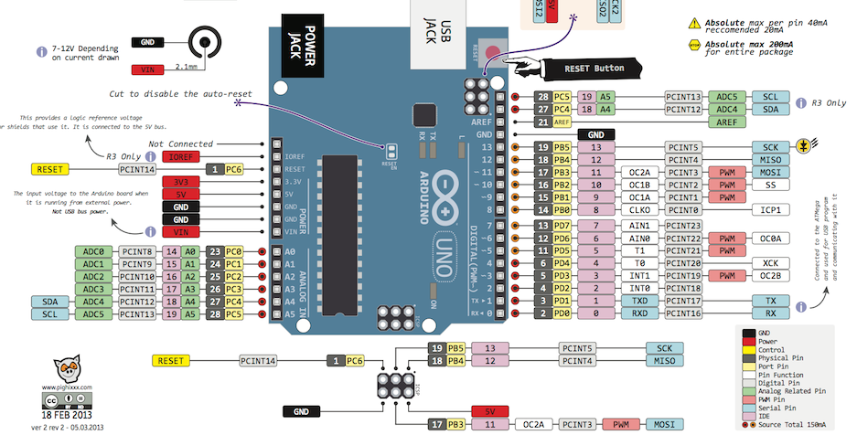
For The radio Connection for the sensor node I followed exactly the Mysensors Guide :
Arduino RFM69
GND GND
3.3V VCC
10 NSS
13 SCK
11 MOSI
12 MISO
2 DI00
And DHT22 is connected on Digital PIN3
Now if I look at the debug from the Sensor Node it seems not able to connect to Radio :+1:
0 MCO:BGN:INIT NODE,CP=RRNNA--,VER=2.1.0
4 TSM:INIT
4 TSF:WUR:MS=0
8 TSM:INIT:TSP OK
10 TSM:INIT:STATID=10
12 TSF:SID:OK,ID=10
14 TSM:FPAR
3141 TSF:MSG:SEND,10-10-255-255,s=255,c=3,t=7,pt=0,l=0,sg=0,ft=0,st=OK:
5148 !TSM:FPAR:NO REPLY
5150 TSM:FPAR
8275 TSF:MSG:SEND,10-10-255-255,s=255,c=3,t=7,pt=0,l=0,sg=0,ft=0,st=OK:
10283 !TSM:FPAR:NO REPLY
10285 TSM:FPAR
13412 TSF:MSG:SEND,10-10-255-255,s=255,c=3,t=7,pt=0,l=0,sg=0,ft=0,st=OK:
15419 !TSM:FPAR:NO REPLY
15421 TSM:FPAR
18548 TSF:MSG:SEND,10-10-255-255,s=255,c=3,t=7,pt=0,l=0,sg=0,ft=0,st=OK:
20555 !TSM:FPAR:FAIL
20557 TSM:FAIL:CNT=1
20559 TSM:FAIL:PDT
Looking at the Gateway have the following
0;255;3;0;9;TSF:LRT:OK
0;255;3;0;9;TSM:INIT
0;255;3;0;9;TSF:WUR:MS=0
0;255;3;0;9;TSM:INIT:TSP OK
0;255;3;0;9;TSM:INIT:GW MODE
0;255;3;0;9;TSM:READY:ID=0,PAR=0,DIS=0
0;255;3;0;9;MCO:REG:NOT NEEDED
....scandone
state: 0 -> 2 (b0)
state: 2 -> 3 (0)
state: 3 -> 5 (10)
add 0
aid 5
cnt

connected with Cluclus, channel 11
ip:192.168.0.15,mask:255.255.255.0,gw:192.168.0.1
.IP: 192.168.0.15
0;255;3;0;9;MCO:BGN:STP
0;255;3;0;9;MCO:BGN:INIT OK,TSP=1
IP: 192.168.0.15
0;255;3;0;9;Attempting MQTT connection...
0;255;3;0;9;MQTT connected
0;255;3;0;9;Sending message on topic: mygateway1-out/0/255/0/0/18
pm open,type:2 0
It does connect to the WIFI but it seems pretty much it, nothing else is happening.
I am honestly loosing my mind I check 25 times the connections. I tried different RFM69 Modules. I triple check the code, Tried to read about everything I can find but I cannot figure out what is wrong.
Please help...
Thanks