HELP !! cannot make Sensor work with RFM69
-
Hi everyone, I decided to jump into the wonderful world of IOT and decided to do a simple project to start : a Weather Station, and at a starting point : a Temperature and humidity sensor (using DHT22).
Sorry in advance for the long email, I tried to put as many details as possible
So My hardware setup is :
Gateway : ESP8266-ESP12 / RFM69CW 868 Mhz
Sensor : Arduino Pro Mini / DHT22 / RFM69CW 868 MhzMy gateway code is :
// Enable debug prints to serial monitor
#define MY_DEBUG

// Use a bit lower baudrate for serial prints on ESP8266 than default in MyConfig.h
#define MY_BAUD_RATE 115200

// Enables and select radio type (if attached)
//#define MY_RADIO_NRF24
#define MY_RADIO_RFM69

#define MY_GATEWAY_MQTT_CLIENT
#define MY_GATEWAY_ESP8266

// Set this node's subscribe and publish topic prefix
#define MY_MQTT_PUBLISH_TOPIC_PREFIX "mygateway1-out"
#define MY_MQTT_SUBSCRIBE_TOPIC_PREFIX "mygateway1-in"

// Set MQTT client id
#define MY_MQTT_CLIENT_ID "mysensors-1"

// Enable these if your MQTT broker requires usenrame/password
//#define MY_MQTT_USER "username"
//#define MY_MQTT_PASSWORD "password"

// Set WIFI SSID and password
#define MY_ESP8266_SSID "xxxxx"
#define MY_ESP8266_PASSWORD "yyyyyy"

// Set the hostname for the WiFi Client. This is the hostname
// it will pass to the DHCP server if not static.
#define MY_ESP8266_HOSTNAME "mqtt-sensor-gateway"

// Enable MY_IP_ADDRESS here if you want a static ip address (no DHCP)
#define MY_IP_ADDRESS 192,168,0,15

// If using static ip you need to define Gateway and Subnet address as well
#define MY_IP_GATEWAY_ADDRESS 192,168,0,1
#define MY_IP_SUBNET_ADDRESS 255,255,255,0


// MQTT broker ip address.
#define MY_CONTROLLER_IP_ADDRESS 192, 168, 0, 2

// The MQTT broker port to to open
#define MY_PORT 1883

/*
// Enable inclusion mode
#define MY_INCLUSION_MODE_FEATURE
// Enable Inclusion mode button on gateway
#define MY_INCLUSION_BUTTON_FEATURE
// Set inclusion mode duration (in seconds)
#define MY_INCLUSION_MODE_DURATION 60
// Digital pin used for inclusion mode button
#define MY_INCLUSION_MODE_BUTTON_PIN  3

// Set blinking period
#define MY_DEFAULT_LED_BLINK_PERIOD 300

// Flash leds on rx/tx/err
#define MY_DEFAULT_ERR_LED_PIN 16  // Error led pin
#define MY_DEFAULT_RX_LED_PIN  16  // Receive led pin
#define MY_DEFAULT_TX_LED_PIN  16  // the PCB, on board LED
*/

#include <ESP8266WiFi.h>
#include <MySensors.h>

void setup()
{
}

void presentation()
{
	// Present locally attached sensors here
}


void loop()
{
	// Send locally attech sensors data here
}```
My Sensor Node Code is :
// Enable debug prints
#define MY_DEBUG

// Enable and select radio type attached
//#define MY_RADIO_NRF24
#define MY_RADIO_RFM69
//#define MY_RFM69_FREQUENCY RF69_868MHZ
//#define MY_IS_RFM69HW
..#define MY_RFM69_NETWORKID 100
//#define MY_RS485

#define MY_NODE_ID 10

#include <SPI.h>
#include <MySensors.h>
#include <DHT.h>

// Set this to the pin you connected the DHT's data pin to
#define DHT_DATA_PIN 3

// Set this offset if the sensor has a permanent small offset to the real temperatures
#define SENSOR_TEMP_OFFSET 0

// Sleep time between sensor updates (in milliseconds)
// Must be >1000ms for DHT22 and >2000ms for DHT11
static const uint64_t UPDATE_INTERVAL = 60000;

// Force sending an update of the temperature after n sensor reads, so a controller showing the
// timestamp of the last update doesn't show something like 3 hours in the unlikely case, that
// the value didn't change since;
// i.e. the sensor would force sending an update every UPDATE_INTERVAL*FORCE_UPDATE_N_READS [ms]
static const uint8_t FORCE_UPDATE_N_READS = 10;


#define CHILD_ID_HUM 0
#define CHILD_ID_TEMP 1

float lastTemp;
float lastHum;
uint8_t nNoUpdatesTemp;
uint8_t nNoUpdatesHum;
bool metric = true;

MyMessage msgHum(CHILD_ID_HUM, V_HUM);
MyMessage msgTemp(CHILD_ID_TEMP, V_TEMP);
DHT dht;


void presentation()
{
  // Send the sketch version information to the gateway
  sendSketchInfo("TemperatureAndHumidity", "1.1");

  // Register all sensors to gw (they will be created as child devices)
  present(CHILD_ID_HUM, S_HUM);
  present(CHILD_ID_TEMP, S_TEMP);

  metric = getConfig().isMetric;
}


void setup()
{
  dht.setup(DHT_DATA_PIN); // set data pin of DHT sensor
  if (UPDATE_INTERVAL <= dht.getMinimumSamplingPeriod()) {
    Serial.println("Warning: UPDATE_INTERVAL is smaller than supported by the sensor!");
  }
  // Sleep for the time of the minimum sampling period to give the sensor time to power up
  // (otherwise, timeout errors might occure for the first reading)
  sleep(dht.getMinimumSamplingPeriod());
}


void loop()
{
  // Force reading sensor, so it works also after sleep()
  dht.readSensor(true);

  // Get temperature from DHT library
  float temperature = dht.getTemperature();
  if (isnan(temperature)) {
    Serial.println("Failed reading temperature from DHT!");
  } else if (temperature != lastTemp || nNoUpdatesTemp == FORCE_UPDATE_N_READS) {
    // Only send temperature if it changed since the last measurement or if we didn't send an update for n times
    lastTemp = temperature;
    if (!metric) {
      temperature = dht.toFahrenheit(temperature);
    }
    // Reset no updates counter
    nNoUpdatesTemp = 0;
    temperature += SENSOR_TEMP_OFFSET;
    send(msgTemp.set(temperature, 1));

    #ifdef MY_DEBUG
    Serial.print("T: ");
    Serial.println(temperature);
    #endif
  } else {
    // Increase no update counter if the temperature stayed the same
    nNoUpdatesTemp++;
  }

  // Get humidity from DHT library
  float humidity = dht.getHumidity();
  if (isnan(humidity)) {
    Serial.println("Failed reading humidity from DHT");
  } else if (humidity != lastHum || nNoUpdatesHum == FORCE_UPDATE_N_READS) {
    // Only send humidity if it changed since the last measurement or if we didn't send an update for n times
    lastHum = humidity;
    // Reset no updates counter
    nNoUpdatesHum = 0;
    send(msgHum.set(humidity, 1));

    #ifdef MY_DEBUG
    Serial.print("H: ");
    Serial.println(humidity);
    #endif
  } else {
    // Increase no update counter if the humidity stayed the same
    nNoUpdatesHum++;
  }

  // Sleep for a while to save energy
  sleep(UPDATE_INTERVAL);
}
The gateway Connection between ESP8266 and RFM69 I followed this Forum topic
RFM69 <-> ESP8266:
DIO0 <-> GPIO4
SCK <-> GPIO14
MOSI <-> GPIO13
MISO <-> GPIO12
CS <-> GPIO15 (AKA NSS)And of course GND + VCC
For The radio Connection for the sensor node I followed exactly the Mysensors Guide :
Arduino RFM69
GND GND
3.3V VCC
10 NSS
13 SCK
11 MOSI
12 MISO
2 DI00And DHT22 is connected on Digital PIN3
Now if I look at the debug from the Sensor Node it seems not able to connect to Radio :+1:
0 MCO:BGN:INIT NODE,CP=RRNNA--,VER=2.1.0
4 TSM:INIT
4 TSF:WUR:MS=0
8 TSM:INIT:TSP OK
10 TSM:INIT:STATID=10
12 TSF:SID:OK,ID=10
14 TSM:FPAR
3141 TSF:MSG:SEND,10-10-255-255,s=255,c=3,t=7,pt=0,l=0,sg=0,ft=0,st=OK:
5148 !TSM:FPAR:NO REPLY
5150 TSM:FPAR
8275 TSF:MSG:SEND,10-10-255-255,s=255,c=3,t=7,pt=0,l=0,sg=0,ft=0,st=OK:
10283 !TSM:FPAR:NO REPLY
10285 TSM:FPAR
13412 TSF:MSG:SEND,10-10-255-255,s=255,c=3,t=7,pt=0,l=0,sg=0,ft=0,st=OK:
15419 !TSM:FPAR:NO REPLY
15421 TSM:FPAR
18548 TSF:MSG:SEND,10-10-255-255,s=255,c=3,t=7,pt=0,l=0,sg=0,ft=0,st=OK:
20555 !TSM:FPAR:FAIL
20557 TSM:FAIL:CNT=1
20559 TSM:FAIL:PDT
Looking at the Gateway have the following
0;255;3;0;9;TSF:LRT:OK
0;255;3;0;9;TSM:INIT
0;255;3;0;9;TSF:WUR:MS=0
0;255;3;0;9;TSM:INIT:TSP OK
0;255;3;0;9;TSM:INIT:GW MODE
0;255;3;0;9;TSM:READY:ID=0,PAR=0,DIS=0
0;255;3;0;9;MCO:REG:NOT NEEDED
....scandone
state: 0 -> 2 (b0)
state: 2 -> 3 (0)
state: 3 -> 5 (10)
add 0
aid 5
cnt

connected with Cluclus, channel 11
ip:192.168.0.15,mask:255.255.255.0,gw:192.168.0.1
.IP: 192.168.0.15
0;255;3;0;9;MCO:BGN:STP
0;255;3;0;9;MCO:BGN:INIT OK,TSP=1
IP: 192.168.0.15
0;255;3;0;9;Attempting MQTT connection...
0;255;3;0;9;MQTT connected
0;255;3;0;9;Sending message on topic: mygateway1-out/0/255/0/0/18
pm open,type:2 0
It does connect to the WIFI but it seems pretty much it, nothing else is happening.
I am honestly loosing my mind I check 25 times the connections. I tried different RFM69 Modules. I triple check the code, Tried to read about everything I can find but I cannot figure out what is wrong.
Please help...
Thanks
Sorry I forgot to mention : I am using the version 2.0 of Mysensors, I use Arduino IDE 1.6.13.
I have check the Voltage to the RFM69 and I am getting 3.28V.. and it is quite stable
For the Gateway, the power is a 9 battery step down via a LM1117 and 2 capacitor of 10uF
For the Node, the 3.3V is supplies by the Arduino Board (I have tried with a UNO and a NANO as well) -
@christophe-cluzel said:
Arduino Board (I have tried with a UNO and a NANO as well)
Uno is 5V powered and RFM69 inputs are not 5V compliant. Perhaps your radio is dead.
@Fabien I supplied the power from the 3.3V output of the Board not the 5V output, I was very careful about this so I really doubt that I fried the Radio
-
You powered your radio with 3.3V but UNO outputs are 5V (except some specials boards like iteaduino). I fried 1 radio with this mistale !
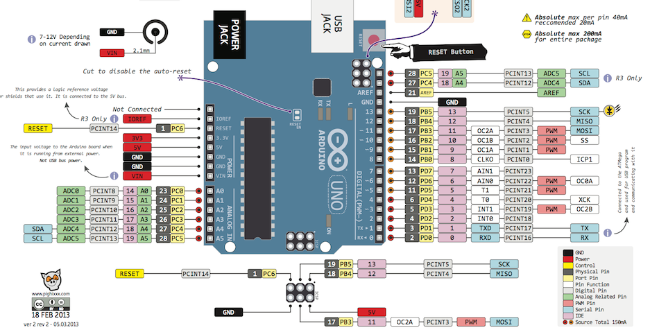
@Fabien This is the pinout of my board
I just double check the output from the 3.3V pinout to be sure and I get 3.28V.
Just to say, I was getting the exact same result with a standalone power supply @3.3V.
Thanks
-
MISO, MOSI, etc ... are 5V outputs and RFM69 unlike NRF24 is not 5V tolerant even if it's powered with 3.3V
@Fabien understand your point and I may have fried it with the UNO, but I doubt it is the cause as I had exactly the same output with my first build with a Pro mini 3.3v, every pin were 3.3V and the debug looked exactly the same. I tried with the UNO after countless attempts with 3.3V boards. But taking your point I will try again with a different radio module and a 3.3V.
Any other ideas?
-
@Fabien understand your point and I may have fried it with the UNO, but I doubt it is the cause as I had exactly the same output with my first build with a Pro mini 3.3v, every pin were 3.3V and the debug looked exactly the same. I tried with the UNO after countless attempts with 3.3V boards. But taking your point I will try again with a different radio module and a 3.3V.
Any other ideas?
Hi,
Following @Fabien idea, I tried with a different RF69M module I had spare with a Arduino Pro Mini 3.3V, I also added a Capacitor of 10uF between the 3.3V of Radio and GND. And I still get the same message.... Arrrgggggg
-
Ok try t add this in your Gateway sketch (before MySensors.h) :
#define MY_RF69_IRQ_PIN 4  // GPIO 4
#define MY_RF69_IRQ_NUM 4
#define MY_RF69_SPI_CS  15  // GPIO 15
I have exactly the same setup on gateway, working fine.
@Fabien I tried yesterday but it doesn't seem to work. I will try again tonight as I did the test in a rush and may have overseen something.
I just thought about something, could it be possible that the RFM69 doesn't get enough power ? I will try with a separate power source tonight to rule out this.
Thx
-
@christophe-cluzel Yes, I got the same problem, I have been 3days to find out the solution, but no result.
I configure the RFM69 with ESP8266 as a gateway and Promini as a node.
The pin connections same with yours.I realy need help to solve the problem
-
@Fabien I tried yesterday but it doesn't seem to work. I will try again tonight as I did the test in a rush and may have overseen something.
I just thought about something, could it be possible that the RFM69 doesn't get enough power ? I will try with a separate power source tonight to rule out this.
Thx
OK I tried again, recheck the wiring, move DI0 to GPIO5 and added the following in the sketch of the Gateway
#define MY_RF69_IRQ_PIN 4  // GPIO 4
#define MY_RF69_IRQ_NUM 4
#define MY_RF69_SPI_CS  5  // GPIO 5
Put the RFM69 in a separate power source, added a 100uF capacitor for the radio.
And still the same result.....
I am litteraly loosing my mind, cannot figure out what else to do...
-
OK I tried again, recheck the wiring, move DI0 to GPIO5 and added the following in the sketch of the Gateway
#define MY_RF69_IRQ_PIN 4  // GPIO 4
#define MY_RF69_IRQ_NUM 4
#define MY_RF69_SPI_CS  5  // GPIO 5
Put the RFM69 in a separate power source, added a 100uF capacitor for the radio.
And still the same result.....
I am litteraly loosing my mind, cannot figure out what else to do...
What I just realized is that neither on the Gateway Debug nor the Node Debug I see the following message :
TSM:RADIO:OK
how do I know that the Arduino or the ESP is communicating or seeing the RFM module ?
-
What I just realized is that neither on the Gateway Debug nor the Node Debug I see the following message :
TSM:RADIO:OK
how do I know that the Arduino or the ESP is communicating or seeing the RFM module ?
I am trying a different approach, I order NRF24L01+ to try tonight and see if I am getting better success with different modules...
-
Using NRF24, actually, mysensors system is no problem. The node (ATMEGA328) and the gateway (ESP8266) can work properly. Now we have 3 nodes and one gateway, working properly. We use MyController.org software deployed in cloud server as the controller.
We want to work on RFM69, because the radio can use 433MHz, while NRF24 use 2.4GHz.
This is the crowded frequency. -
Using NRF24, actually, mysensors system is no problem. The node (ATMEGA328) and the gateway (ESP8266) can work properly. Now we have 3 nodes and one gateway, working properly. We use MyController.org software deployed in cloud server as the controller.
We want to work on RFM69, because the radio can use 433MHz, while NRF24 use 2.4GHz.
This is the crowded frequency.@maman I agree, but I am trying to get my project starting to be fair I do not live in a Mansion and my further sensor will be the one in the Garden for the weather station and the Watering system. So maybe the NRF24L01+ will be ok.
I will keep working in parallel on the RFM69, but right now I feel that I am just wasting time and getting nothing achieved.
I have new RFM69 on Order (RFM69HW instead of the RFM69CW I currently have) I am quite hoping that getting to a differet version of the RFM69 will solve the problem...
-
hmm..something is wrong with your hardware or settings, with pro mini or esp it should work..
What frequency do you want to use?
and maybe a dumb question, but in case.. have you soldered an antenna on your rfm69 modules?@scalz I use 868 Mhz, I soldered antenna (82 mm), trust me there is no dumb question :)
I get what you say, it should work but I cannot figure out what is wrong
Hello! It looks like you're interested in this conversation, but you don't have an account yet.
Getting fed up of having to scroll through the same posts each visit? When you register for an account, you'll always come back to exactly where you were before, and choose to be notified of new replies (either via email, or push notification). You'll also be able to save bookmarks and upvote posts to show your appreciation to other community members.
With your input, this post could be even better 💗
Register Login