@bjornhallberg The sensors are working fine and have been installed in my home for the last couple of years. Some optimisation needs to be done to the code, that i have not done. This is more connected to understanding when the mysensors network is in "range" as i want to fallback on the manual knob if the mysensor network is inactive for some reason or if i sell the house and the controller goes with me.
Posts made by Denke
-
RE: Wirsbo/Uponor thermostat replacement
-
RE: 💬 Wirsbo/uponor thermostat
@hepal
Hi The thermostats use mysensors serial gateway to communicate with the openhab that runs on a raspberry Pi 2. I run openhab 2.0 but in the beginning i was running 1.7.x -
RE: 💬 2 channel in wall dimmer
The project does not work without neutral wire
-
RE: 💬 2 channel in wall dimmer
No i have not tested any minimum loads at the moment, this is one of the next steps
-
RE: 💬 Wirsbo/uponor thermostat
HI @dexterbot
Here is the code for the openhabItems
/* Thermostats /
/ Hall */
Number Hallway_Temperature "Temperature [%.1f]" <temperature> (Temperature, C_Hallway, gMS) { channel="mysensors:hvacThermostat:gateway:Hallway_Temperature:temp" }
Number Hallway_SetPoint "HVAC/Heater set point " <temperature> (gMS) { channel="mysensors:hvacThermostat:gateway:Hallway_SetPoint:hvac-setPoint-heat" }
String Hallway_FlowState "Mode of heater [%s]" <heating> (gMS) { channel="mysensors:hvacThermostat:gateway:Hallway_FlowState:hvac-flow-state" }
Number Hallway_KnobTempVar1 "Knob temperature [%.1f]" <temperature> (gMS) { channel="mysensors:hvacThermostat:gateway:Hallway_KnobTempVar1:var1" }
String Hallway_FlowMode "Running mode" <heating> (gMS) { channel="mysensors:hvacThermostat:gateway:Hallway_FlowMode:hvac-flow-mode" }
Number Hallway_HystLowVar3 "hyst low [%.1f]" <temperature> (gMS) { channel="mysensors:hvacThermostat:gateway:Hallway_HystLowVar3:var3" }
Number Hallway_HystHighVar4 "hyst high [%.1f]" <temperature> (gMS) { channel="mysensors:hvacThermostat:gateway:Hallway_HystHighVar4:var4" }
Number Hallway_UpdateTimeVar5 "update time (s) [%d s]" <clock> (gMS) { channel="mysensors:hvacThermostat:gateway:Hallway_UpdateTimeVar5:var5" }Things
Bridge mysensors:bridge-ser:gateway [ serialPort="/dev/ttyUSB0", sendDelay=200, baudRate=115200, skipStartupCheck=true ] {
/** define things connected to that bridge here */
hvacThermostat Hallway_Temperature [nodeId="59", childId="0"]
hvacThermostat Hallway_SetPoint [nodeId="59", childId="0"]
hvacThermostat Hallway_FlowState [nodeId="59", childId="0"]
hvacThermostat Hallway_KnobTempVar1 [nodeId="59", childId="0"]
hvacThermostat Hallway_FlowMode [nodeId="59", childId="0"]
hvacThermostat Hallway_HystLowVar3 [nodeId="59", childId="0"]
hvacThermostat Hallway_HystHighVar4 [nodeId="59", childId="0"]
hvacThermostat Hallway_UpdateTimeVar5 [nodeId="59", childId="0"]
}
sitemap
Group label="Thermostats" icon="heating"{
Frame label="Hall"{
Text item=Hallway_Temperature
Text item=Hallway_FlowState label="State [%s]"
Setpoint item=Hallway_SetPoint label="Set point [%.1f]" icon="temperature" minValue="0.0" maxValue="32.0" step="0.1"
Text item=Hallway_KnobTempVar1 label="Knob temperature" //Knob temperature
Text item=Hallway_FlowMode //Running mode
Setpoint item=Hallway_HystLowVar3 label="Hysteresis L [%.1f]" minValue="0.0" maxValue="5.0" step="0.1"
Setpoint item=Hallway_HystHighVar4 label="Hysteresis H [%.1f]" minValue="0.0" maxValue="5.0" step="0.1"
Setpoint item=Hallway_UpdateTimeVar5 label="Update time (s) [%d]" minValue="1" maxValue="4096" step="1"
}
} -
RE: 💬 Wirsbo/uponor thermostat
Hi Tomas
I have only replaced the thermostats not anything else in the system.
This thermostat is a replacement of my Cosy thermostat (art no 804661), but i think it should work also for the following article numbers (80466, 80465, 804651 and 80464). This thermostat only works as a on/off for the valve, I did not spend any time on the night temp function. I have connected the thermostat to a transformer unit (art no 80460) which in principle only converts 220 v to 24 V which is then connected to the thermostat. When the thermostat turns on it passes on the ~24 V signal to the valve.I will upload a schematic to the project
-
RE: openHAB 2.0 binding
Hi all
I have a problem when my raspberry pi and mysensors/openhab when i do a restart. The problems seems to be ralated to the serial gateway and that the openhab dont find it or has the wrong settings.Openhab starts when i make a reboot
I checked the serial by typing
stty -F /dev/ttyUSB0
response was
Seems here that the baudrate is wrong as my settings in the things file is
What i did to make it work was just to change this to use baud 9600 and then back to baud = 115200
after this it looked like
And everything started to work nicely
Does anyone now what the cause of this is and also how to fix it?
-
RE: Mini motion detector based on Biltema PIR LED
And now everything is connected together.
I had to change some values on the resistors.
R6 = 10k and C4 = 10 nF gives 2.5 seconds ON time. I also changed the sensitivity from 4 s to 0.05 Seconds, I am considering changing this a bit to some greater value to increase the time some.
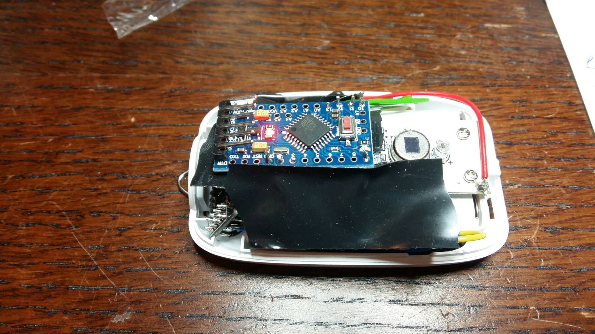
I also need to do some changes to the Arduino board as the on led is always on and i think i should remove the regulator to save some more power.
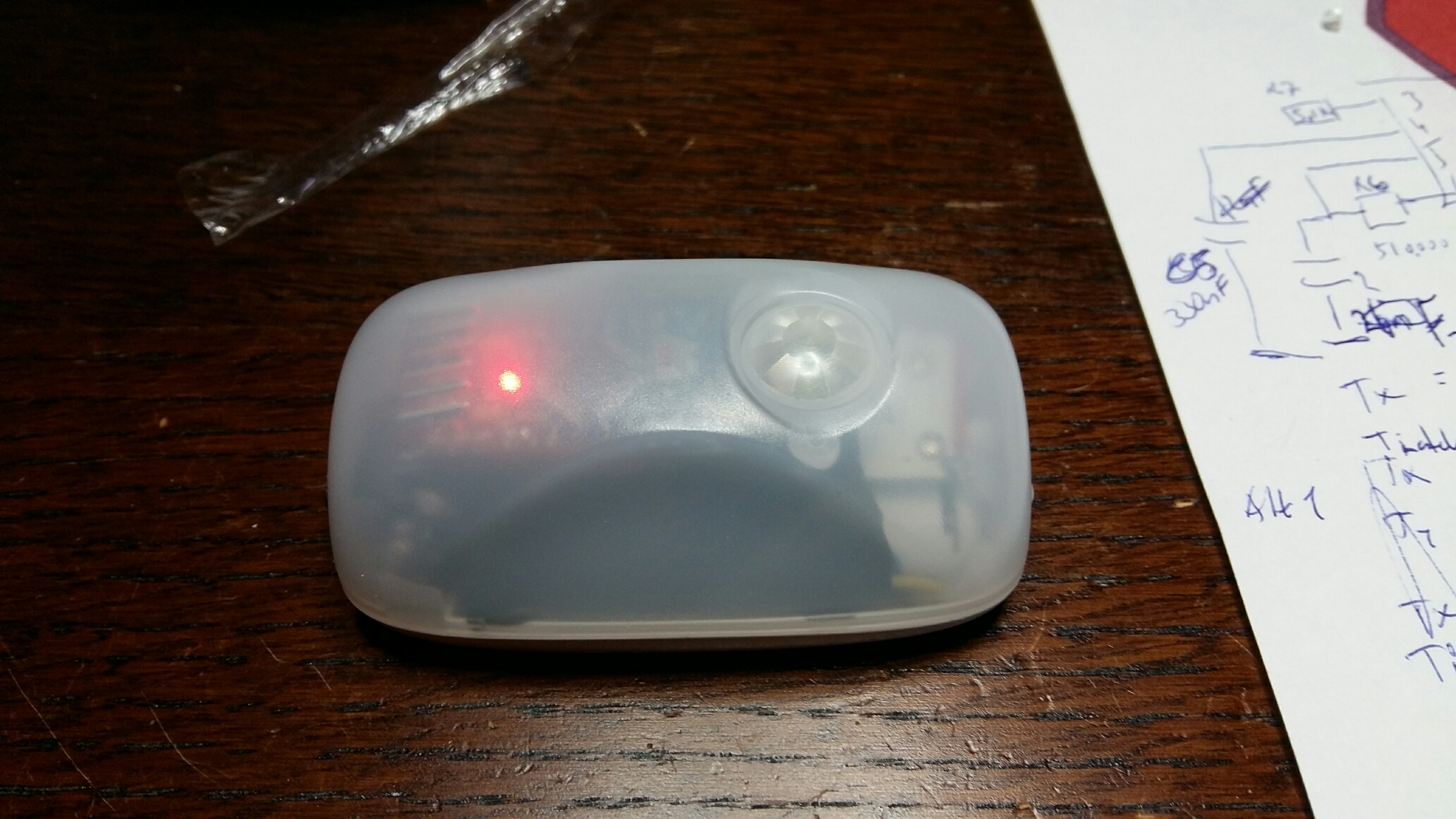
-
Mini motion detector based on Biltema PIR LED
Just for the fun off it i bought a Biltema presence controlled LED lamp for 79 SEK ~9$ having in mind that i should be able to use the nice box and interior to build myself a "cheap" motion detector to add to mySensors project.
http://www.biltema.se/sv/Bygg/Belysning-och-lampor/LED/Narvarostyrd-minilampa-2000033627/
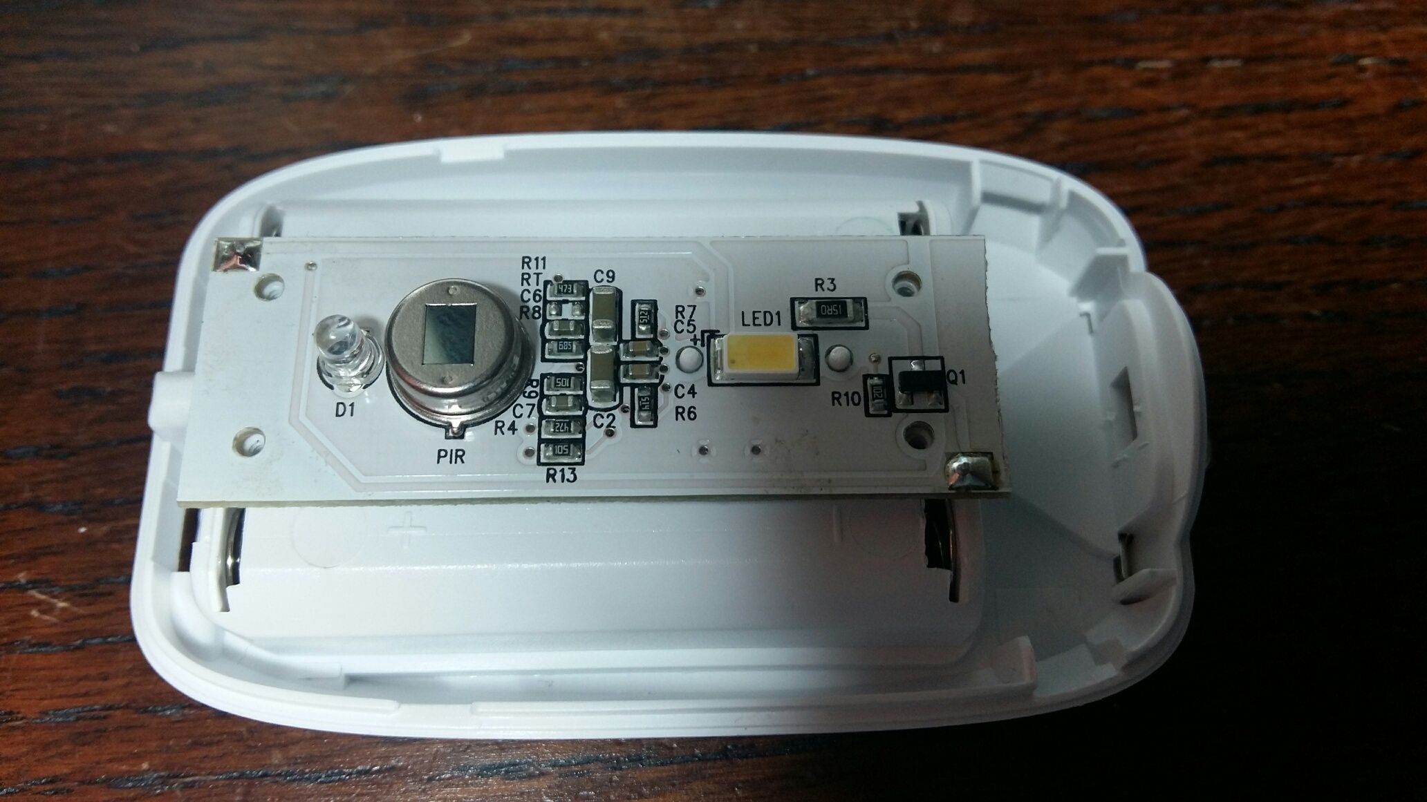
I started by opening the lid and remove the board. This was a little troublesome as i had to compress the battery connector to get it out of its position, but i managed.
After that i tested different ways of how to fit in the Arduion mini and the RF in to the box. Unfortunatly i could not get it in without making the PIR sensor board smaller. I just cut down the board at the near the GND connector.
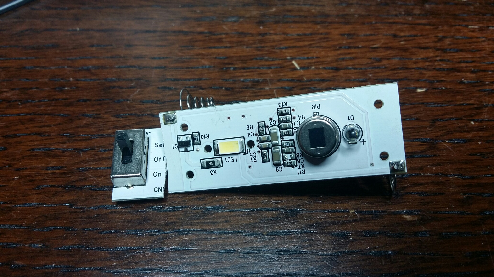
After this i had cut off the VCC and the motion output so i had to fix that by soldering wires for VCC and motion output shown below. connected pin1 and 8 fixin the VCC. and solderded the Via hole to the testpoint to fix the motion output from pin 2. Also i needed to cut the track just right of C3 to disable the fotoresistor so that the sensor work also in daylight.
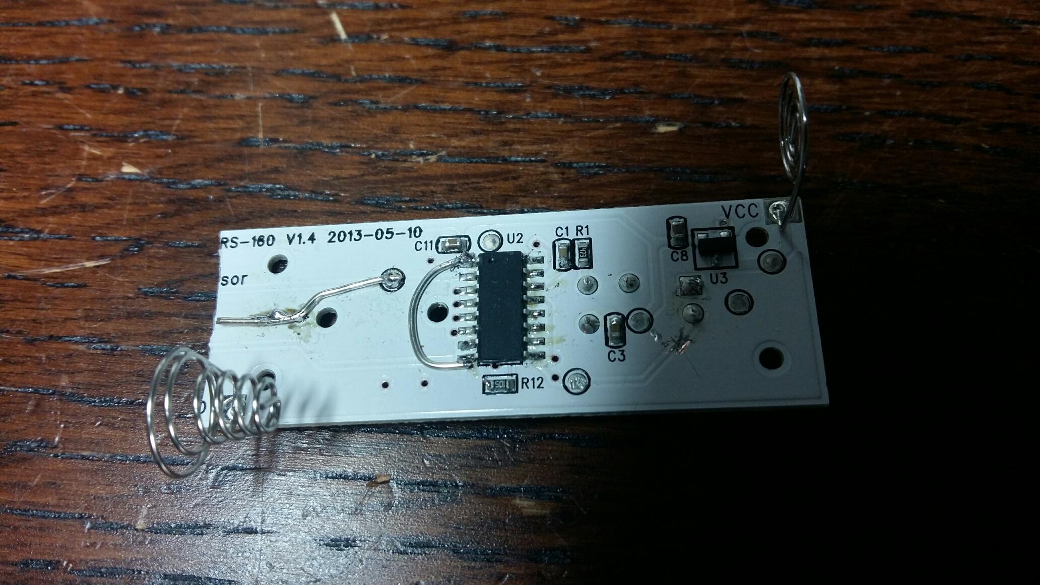
I assembled back the board. Also you will need to replace the LED with a 10k ohm resistor (to reduce the current when activating) and then connect the Arduino sensor input to the R3 right side. This should give an active low trigger pulse.
And then i placed the component as i see that they should fit.
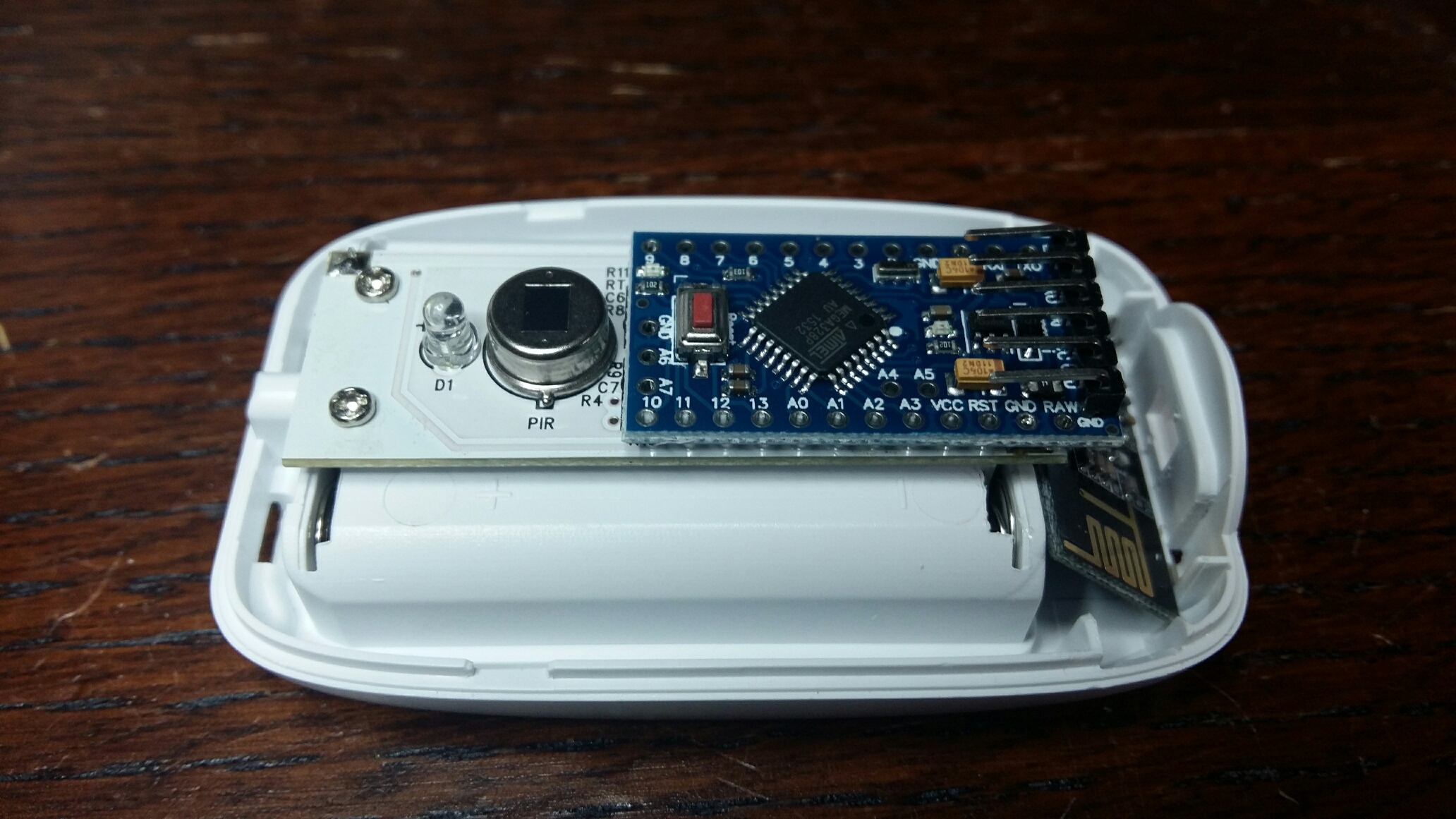
Now comes the next step to wire the R Fboard to the Arduino and then connect the motion output to the input of the Arduino.
There might be some changes needed for setting up the right length of the pulses on the motion detector. I have to investigate which of the R's and C's just right to the detector that does this.This is as how far i came today.
Hopefully this will be one of those projects i finish.
I will make updates on the progress
-
RE: openHAB 2.0 binding
@Denke
I cant find V_PRESSURE connected to CHANNEL_BARO below, can that be the reason? -
RE: openHAB 2.0 binding
Hi
Is there anybody that have had a problem with the S_BARO and the V_PRESSURE channel?I try to send a value on this channel as 1.2 I can see that the serial gateway receives it
23:10:51.808 [DEBUG] [g.mysensors.protocol.MySensorsReader] - 0;0;3;0;9;read: 163-163-0 s=10,c=1,t=4,pt=7,l=5,sg=0:1.2
I set up the channel as i have done for alot of other channels through the paper ui. where i link the channel to an item.
The item file looks like this
String Pool_Pressure "Pressure [%s]" <pressure> (gPool)the sitemap file looks like this
Text item=Pool_Pressureresult is this
The field never gets updated.
any suggestions? -
RE: openHAB 2.0 binding
@meju25 I saw this from a management perspective.
I have one device, my pool controller, that has multiple sensors and also channels per sensor just as HVAC that has a sum of channels. In my case i implemented a number of sensors in different types of channels "S_HVAC, S_LIGHT,...." what i see that it gets messy when you try to see if the channels are active or the pool control is active it has multiple sensors.So maybe a suggestion is to maybe implement this in the mysensors instead of in the openhab binding.
In that case i would like to add something that allows me to tell what channels are in a "sensor" by combining differnt channels and sensor types.I don't know if i got my message through.
But all this is mainly for management of my devices so that this gets less messy
-
RE: openHAB 2.0 binding
Merging sensor to one
Hi
I have been thinking and i think it would be nice if there is a way to merge sensor data to one in the mysensors binding.Background
I am trying to build a pool control based on mysensors and i have a lot of options that i wan it to handle. For example:- on/off of my pool pumps (S_LIGHT)
- on/off of lights around the pool (S_LIGHT)
- thermostat function for heaters (S_HVAC)
- measuring pressure on pump (S_BARO)
- measuring consumed power on pump (S_POWER)
All this are using the same sensor ID and getting own child IDs. When they now are brought in to openhab they appear as single sensors
Is there a possibility to get an automatic merge for thes combined sensors?
And what do you think about the idea.
Or is there already a solution that exist that I am not aware aboutexample from paper UI
with openhab poolcontrol view
-
RE: openHAB 2.0 binding
Hi all
Implemented a barometric sensor "pressure meter" that i sample in the sensor. Then i send the value Through "BARO". I can see in both the sensor output and the openhab debug that i receive a value for example "1.2".
I try to display this in the openhab and i dont get the Text item to update.
Anyone know how this can be as i have other values that i am able to display.
line in .items
String Pool_Pressure "Pressure (bar) [%s]" <pressure> (gPool)line in .sitemap
Text item=Pool_Pressureany help is appriciated as i have tried different options with Number and so on
-
RE: openHAB 2.0 binding
@TimO said:
log:set DEBUG org.openhab.binding.mysensors
I tried this. From what i can see after doing some attempts to connect.
First & second attempt
This is what i get after just opening the serial gateway thing and edit and sav, seems as openhab then tries to reconnect with the gateway.
third attempt
It seems like it gets connected, bu some error occurs which closes the connection again
Forth attempt actually seemed to get things going
Now to the next step.
I have a device that was just given a new address from the my sensor binding. I restarted the sensor and waited to see it in the inbox (this is something that i have seen working occasionally( sometimes it gets in there sometimes it don't. I added the device manually and it seems to work. How ever my links dont work -
RE: openHAB 2.0 binding
Hi all
Im having major difficulties getting openhab to discover my serial gateway. I have had it working and i have got input from my sensors. But every know and then when i have restarted the computer the serial gateway is offline. The COM port is active and working according to Windows.
I have tried to restart the computer, unplug and plug the usb several times. Doing this i have at some occasions got everything to work again.Any suggestions what it can be that is being the problem.
I also think i have found a bug.
If i for example take the gateway or an sensor that has been added which is marked off line. Then if i press edit on that one and just press the "save" button then it shows that it is on line even though i seriously doubt it is. As i dont get data from my sensors.
Also how do i get the debug window (console view) to show for openhab?
-
RE: openHAB 2.0 binding
@Denke
You look and you look, then you ask someone how to do.Then you look again and you find it:)
, true after the set message in send did the trick.
gw.send(msgSetpointHeat.set(setTemp,1),true); -
RE: openHAB 2.0 binding
@andreacioni
Hi I have trouble finding out how to get my node to request ack, do you know how. I think i have figured out how to handle incoming message to check that the ack is received ant that is through message.isAck().But how do i get the node to send a request for ack?
-
RE: openHAB 2.0 binding
Does the ack signaling work in the binding? I have a sensor that will request an ack from the gateway. Does anyone know if this is working?
-
RE: openHAB 2.0 binding
@hek SO if i understood it correctly from reading info from this link. My question below is answered by that it is beeing implemented as we sspeak?
-
RE: openHAB 2.0 binding
Open query.
I think it is a bit boring that when you give the sensor a new adress that you have to power cycle the device to get it added. I can see that the sensor is starting to transmitt with the new address but The binding is not finding it as a new device. I can see that this happens becouse the sonsor dont present it self to the binding. how ever what about implementing a feature that asks the sensor for data when it just gave out a new address. I have also asked for mySensor to add the feature that when the node gets a new adress that it should present it self.Which way do you see as best? Or is it nothing that can be one?
-
RE: openHAB 2.0 binding
@andreacioni i support your idea to implementing this in the bindning.
-
RE: 2 channel in wall dimmer
Hi just wanted to get an update on this project.
I have assembled 2 pcb (not all components) to start debug the processor platform and surroundings. Unfortunatly i got a bit stuck as i have problems loading the boot loader. I have tried to use the process suggested on arduino.cc using an nano as ISP. I get alot of strange behaviours and are not able to upload.Any tips and tricks is well received if you have any.
Othervise i will rest this project for a couple of weeks to be able to finnish my other thermostat project as well start a new, as the pool season is around the corner. And i really would love to be able to corntol pupm, lghts read temperatures and other stuff.
But if i find some good tricks i will pursue the goal to finnish this in wall dimmer before summer.
-
RE: 2 channel in wall dimmer
First components added after a visit to the lab at work and some soldering under the microscope
-
RE: Wirsbo/Uponor thermostat replacement
2 boards completely assembled and working as expected. 3 more to go after ordering the missing components. Now some last fixes to the code so that memory can be wiped by pressing a button and also the check if connected to the home automation system if not a fallback should be initiated
-
RE: 2 channel in wall dimmer
@ahmedadelhosni Have not started the assembly of these boards yet. Im currently doing assembly of my other project Wirsbo/Uponor thermostat replacement. And those boards seems to be fully functional.
I will post a picture as soon as I get it assembled
-
RE: Wirsbo/Uponor thermostat replacement
Now the code is tested against openhab2.0 after some work adding HVAC in the binding. Will make a pull request for the binding part soon
-
RE: 2 channel in wall dimmer
@ahmedadelhosni
Hi I have used 1M as bleeder in 0603 size. This resistor should be able to handle around 0.1W.If i have calculated right the power in the bleeder resistor should be around 0.05W
-
RE: 2 channel in wall dimmer
Finally new boards have arrived..
Assembly will start soon:)
-
RE: Wirsbo/Uponor thermostat replacement
Finally my new boards have arrived, made some mistakes on the first one.
-
RE: Plastic enclosures
Thanks for the suggestion. Just to clarify what i search for. I am looking for something that has a nice look to be placed indoor. I have found a lot of units that is with electronics internally. What i need is only the enclosure.
-
Plastic enclosures
Hi
I am looking for plastic enclosures for PIR motion sensors,any suggestionsI am also looking for a supplier that can do plast moluding for my custom made In wall dimmer and nd maybe a motion sensor project
-
RE: openHAB 2.0 binding
@TimO
Hi Tim
I use gw.present(0, S_HVAC); to present the sensor to the controllerI use the following messages to send information
MyMessage msgTemp(0,V_TEMP); //temperature of thermostat
MyMessage msgFlowState(0,V_HVAC_FLOW_STATE); //tells if the thermostat is active HeatOn or off
MyMessage msgSetpointHeat(0,V_HVAC_SETPOINT_HEAT); //used for setting wanted temperature
MyMessage msgKnobTemp(0,V_VAR1); //gives the wanted manual temperature set on the thermostat knob (used for fallback when home automation dont work
MyMessage msgRunningMode(0,V_VAR2); //running mode internal or external internal = knob value used, external set by home automation
MyMessage msgHystLow(0,V_VAR3); //used if hysteresis needs to be changed (low value)
MyMessage msgHystHigh(0,V_VAR4); //used if hysteresis needs to be changed (high value)
MyMessage msgUpdateTime(0,V_VAR5); //used to set system sampling/update timeAll of the above values are sent out from the thermostat at update sampling time interval.
V_HVAC_SETPOINT_HEAT(msgSetpointHeat), V_VAR3(msgHystLow), V_VAR4(msgHystHigh), V_VAR5(msgUpdateTime) can be set from the controller to update the thermostat parameters
-
RE: openHAB 2.0 binding
I need support for HVAC device, how much work is there to be done to get that included.
I have made a thermostat controller for my Wirsbo floor project can be found under myprojects wirsbo uponor thermostat replacement
-
RE: 2 channel in wall dimmer
Boards are now ordered. Lets hope they will work fine. I have some doubts about EMI coming from the boards when dimming. So now it will be measure and correct if needed
-
RE: Wirsbo/Uponor thermostat replacement
New boards ordered. Took the oportunity to add an extra connector for SPI. So this in combination with the SDA/SCA will make it possible to add an OLED.
-
RE: 2 channel in wall dimmer
@ahmedadelhosni That all has to do if you have some sort of bleeder. or something that uses the charge. So in my design on the secondary side (+5V) there is always something that consumes the current. On the primary side you can see that there is bleeder resistors in paralell with the capacitor. So it should be safe from that aspect
-
RE: 2 channel in wall dimmer
Thanks Tante-ju and Scalz for helping out with the answer. This is why i stated that you need to treat the equipment as hot, becouse that you don't have control of the reference to ground. But as long as it stays "inwall" and you are using 230 V rated switches on the low voltage switch then the insulations shall be ok and safe. But as soon as you open up and work with it you need to treat is as hot.
-
RE: 2 channel in wall dimmer
@m26872 I guess there will be space for 1 or 2 relays. But it will be crowded, but nothing is impossible
-
RE: 2 channel in wall dimmer
@ahmedadelhosni Going slowly at the moment had to do a respin on my thermostat project as i have made some small errors. Some of the design is the same so i will verify some things on the other design. Also waiting for chinese new years to end
-
RE: 2 channel in wall dimmer
@Ivan-Z Thanks I will look in to this design and what it means to the design
-
RE: My MYSX Multisensors board
If you have space issues i think you should go for 0402 size, its not that hard to solder if you have a magnifing lamp, a good soldering iron, a tweezers and some thin soldering iron
-
RE: My MYSX Multisensors board
For the box
Is the battery kept away from the antenna part of the design. My question is is the board longer than an AA battery including battery "connectors" -
RE: My MYSX Multisensors board
Really great project. Thanks for giving me ideas and inspiration. This was my next step to go for after my thermostat and dimmer project
-
RE: 2 channel in wall dimmer
@ahmedadelhosni
Hi This circuit is not tested yet and can as you describe put out some or as stated a lot of EMI (Electro Magnetic Interference). I have not yet taken this in to account when designing this but have had it in the back of my head for something to look in to.The snubber circuit is more to protect agains "current rush" when you switch of an inductive load. This is actually something you use on the 5 volt side of relays to protect the transistor from breaking down. Andyou should also use on the output side of a relay for example if the cable you are runnigng is long or you want to switch of an inductive load
-
RE: 2 channel in wall dimmer
@hek Its more that i at this moment have not gone through the pros and cons of open hardware. And this is something i will read up on. So Im not saying that i will not share, but i need my time to go through it.
-
RE: 2 channel in wall dimmer
I have not descided yet if this is something i will sell or not so before i take that descision i will not share the actual design files but I will be happy to answer questions around the design and the considerations i have taken.
I might post a question later on if someone wants to join on first ordering for the prototypes/functional version, as this is the first step, primaraly to equip my house with these gadgets. In such a case i will offer those dimmers for a very low cost
-
RE: 2 channel in wall dimmer
Hi all
I will try to answer your questions.Q: what sort of switch would be on the wall?
For this design i would recommend that you use 230 V rated switch to control the dimmer. The output is still only 0V that you switch on and off. But the design is made in such a way that if you get short circuit on the capacitor in series in to the rectifier there can be 230 V on the input pins ( very unlikely because of other things will burn) but it can happen.Q: How are you sure that this hardware circuit …….
Doing a little benchmark and understand how dimmers and switches from NEXA or similar are working. Actually I ripped them apart and found out that they were using transformer less designs. From that I Googled this and read up on the topic as well as discussed this with colleges of mine. I then changed some parts as the transformerless design would in simulation not give more than 10mA so I added the MAX 17552 circuit in between and set the input voltage to 24 V with the zener diode and by that I will be able to draw about 30 mA (starting current of the circuit that I tested is around 24 mA).
Q: I suspect this unit is going to be mounted in wall behind……..
Yes of course but just use it as the switch, what I mean is that don’t use at ordinary switch were 230 V is applied. The circuit is designed to just feel a logic zero on one of the inputs. ( just make sure that you read my first reply above for safety reasons)
Q: can we control Celling fan using this dimmer.
Should not be a problem as I have used Triacs that are made for inductive load (not tested though). But the fan should not consume more than 4A. I also have not tested from a heat perspective how much power I can have running in the system. It might be less than the 2 channels times 4A. -
RE: 2 channel in wall dimmer
First attempt to see how a box could look like
Diameter 56 mm 50 mmside to side
-
RE: 2 channel in wall dimmer
I have now made a new layout on this where i have added a Thermal cut off resistor as well. This made me rearrange some things on the board. At the moment I am still investigating the best triac to use and if it will be "quiet" enough on the line if i use the snubberless version of the triac.
-
RE: 2 channel in wall dimmer
What i mean is that care needs to be taken when using this type of design when it comes to handling. The main thing is if the 0.33uF capacitor breaks then there could be 240 V on the low voltage side, so as long as you handle the equipment with respect to this then i believe it will be safe. That's why i will only use the inbuilt wall switch together with this as that one is rated for the 240 volts.
Also there can be a grounding issue as this design is floating. This is why i will not connect my programmer to this with 240 Volts connected, most likely nothing will happen, but better be safe than sorry, don't want to damage my computer.
The only thing i think i will add in the design is a thermal fuse to be on the safe side. I have one of these ACS712 that I can read the current, but then everything is up to the programming to make sure you don't have any over current in the system that causes heat.
I have also added 0.75 mm isolation distance between traces on the board as well as having thick enough lines for the 4A that I have designed for. -
RE: 2 channel in wall dimmer
Ther Triac in the design is T405-600B which should be able to handle 4A current if i read the spec right. I have not tested it yet so i dont know how much power dissipation there will be
-
RE: 2 channel in wall dimmer
Here is the schematic of the conversion from 240 V to 5 V. It could work for 110 V as well but that needs to be simulated.
Be aware that by this type of design with the transformer less design considerations needs to be taken when connecting computers and other stuff. So my recommendation would be to program everything without 240 V attached.
I have used the 328P
The picture below shows the AC to DC conversion. This design can handle ~30mA on the 5V side.
The AC is on the left hand side. the 0.33 uF capacitor in series on the 240 sets the maximum current, which should be around 10 mA on the AC side (Theoretically 25mA, simulated 10mA).Be aware that not all values in the design below is correct to get the MAX 17552 to work.
-
2 channel in wall dimmer
Hi here is my 2 channel dimmer project that I am working on. The project will fit a 70 mm in wall round box. There are still some things to consider in the design, but i expect that i will be making an order within the next 2 weeks for this prototypes.
If there is interest i can share more about the project
-
RE: Recommendation: power supply
have you had a look at transformer less designs? One capacitor some zener diodes and a rectifier bridge
You need to know what you are doing, but if all is in the same box then i think it is safe. The design can give you around 25mA. I will use it myself for a 2 channel dimmer project that I am working on.If you rip apart a Nexa Switch box or similar you will find this designs in there.
http://www.jula.se/catalog/el-och-belysning/elinstallation/plug-in-produkter/fjarrstrombrytare/fjarrdimmer-408053/
or
http://www.jula.se/catalog/el-och-belysning/elinstallation/plug-in-produkter/fjarrstrombrytare/dimbar-fjarrstrombrytare-408051/
Also LED light bulbs seems to use this principleBut you have to read up if this is something that suits your need.
Also dont connect your computer to the programming port at the same time as it is powered on.
-
RE: Wirsbo/Uponor thermostat replacement
I hope so to.
At the moment i struggling with the best way to present this sensor to my openhab and also what is the best way to set it up.
Parameters in
-remote requested temp //temp requested by the home automation system/user (mandatory)
-hysteresis low, hysteresis high //where to open and close from requested temp point (Setting for the Tech user) 0.5 will be default
-Update time //how often shall i regulate/change and measure (Setting for tech user) 1min will be defaultParameters out
-Temperature
-valve state
-Info field:
--Direct requested temp (knob reading)
--Remote requested temp (See above)
--Running mode internal/external (fall back if no communication is reaching the thermostat, but thermostat info is visible in system)
--hysteresis set in thermostat
--Update timeAnyone got any thoughts on what is the best way to present this.
-
Wirsbo/Uponor thermostat replacement
Hi all
Here is my first mysensors HW that i developed and also my first post. Not all functions are tested at the moment.
I started by analyzing the current thermostat on size and function. Then i took all the info and started working with it in designspark.My plan is to use this with Openhab
Spec
-Should be able to open/close valve in Uponor system
-Should in the future be able to open the valve from 0-100% (Think i need to change valves for this)
-Should fit in the Wirsbo thermostat mechanics
-The system shall fall back to "old thermostat" function if the home automation stops working by using the knob setting
-The system shall be built as much as possible on cheap components that could be bought on for example ebayOld System
New system
If only on/off function is requested then the MOC 3023 could be replaced by a a new one with zero crossing detection and then also the zero crossing detector can be omitted (IL250 in the schematic)Schematic
Result
The HW fits in the old casing
Not all components are mounted at the moment as i have not received them yet, but the board have partial functions