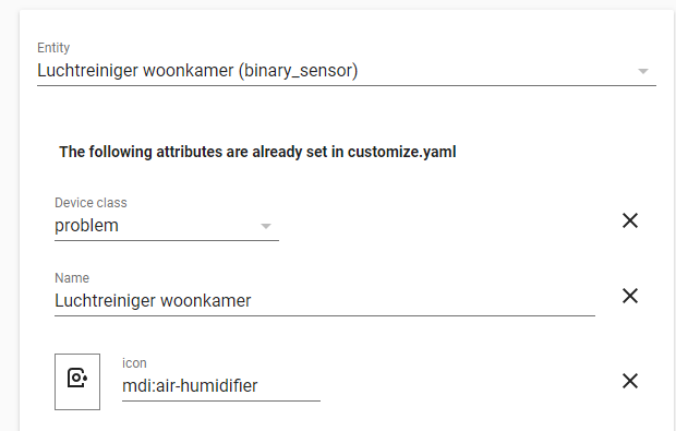
Skip to content
  • MySensors
  • OpenHardware.io
  • Categories
  • Recent
  • Tags
  • Popular
Skins
  • Light
  • Brite
  • Cerulean
  • Cosmo
  • Flatly
  • Journal
  • Litera
  • Lumen
  • Lux
  • Materia
  • Minty
  • Morph
  • Pulse
  • Sandstone
  • Simplex
  • Sketchy
  • Spacelab
  • United
  • Yeti
  • Zephyr
  • Dark
  • Cyborg
  • Darkly
  • Quartz
  • Slate
  • Solar
  • Superhero
  • Vapor

  • Default (No Skin)
  • No Skin
Collapse
Brand Logo
E

edweather

@edweather
About
Posts
15
Topics
5
Shares
0
Groups
0
Followers
0
Following
0

Posts

Recent Best Controversial

  • Rebuild of my broken 433mhz Cresta/hideki UV-Sensor
    E edweather

    Hello,

    I just started with arduino and mysensors and I would like to share my first steps (re)building my broken uv-sensor.
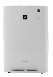
    I bought the orignal TS704 UV sensor about two years ago. A few weeks ago it stopped sending acurate UV readings. On lots of placesa on the internet there are complaints abouts this sensor and the relative short lifetime. Main reason I think is water leakage in the sensor. I didn't want to buy a new one because the problem would be back within 2 years and they are realy expensive at the moment (about €70).
    Then I found the mysensors site in my quest to fix my broken device and my first sensor project was born!
    I ordered the pieces I needed and started to build.
    First the gateway, connected to domoticz which was easy as I connected it directly to the raspberry pi using the pigatewayserial software. Antenna directly connected to the Pi so no Arduino board needed!.
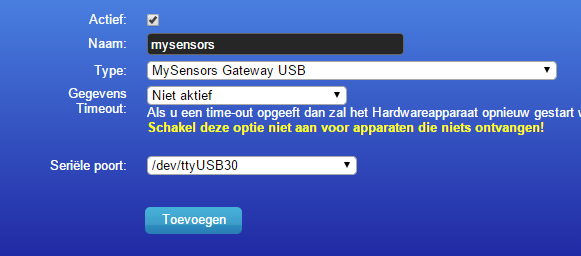
    Changed tty TTY_NAME := /dev/ttyMySensorsGateway to tty
    TTY_NAME := /dev/ttyUSB30 in the makefile because Domoticz cannot use ttyMySensorsGateway.
    After that It was easy to add the serialgateway to Domoticz!

    upload-e224b990-a645-4097-a509-02e4a7273ae3

    my list:
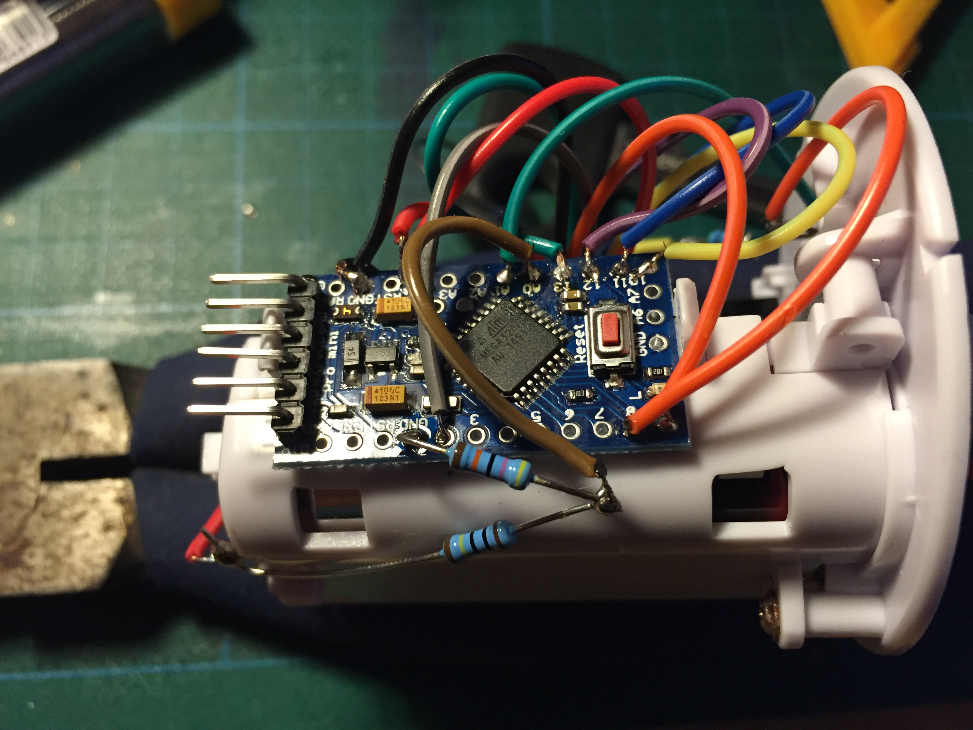
    Arduino pro mini 8mb 3v
    UVM-30a UV sensor
    NRF24L01+ 2.4GHz Wireless Transceiver
    TS704 UV sensor housing including 2xAA batery compartment
    Used the default sketch with pin A0 instead of pin 3 (http://www.mysensors.org/build/uv)

    On my breadboard I had things up and running quite easy but the readings were strange. Even at night there was UV light measured. The problem was a mismatch between the intructions on this website about the out pin to use and the one mentioned in the sketch. Sketch showed pin A0 as OUT but website showed pin 3 as OUT.
    @hek has confirmed that A0 is the correct pin. Website will be updated. (is updated now)
    I was mislead because with nothing connected to pin A0 it still gives you output data.
    It's also possible to use 3V for the UVM-30A instead of only 5volt I found this in the spec sheet.

    So the stepup from 3 to 5v is not needed I think?

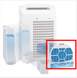
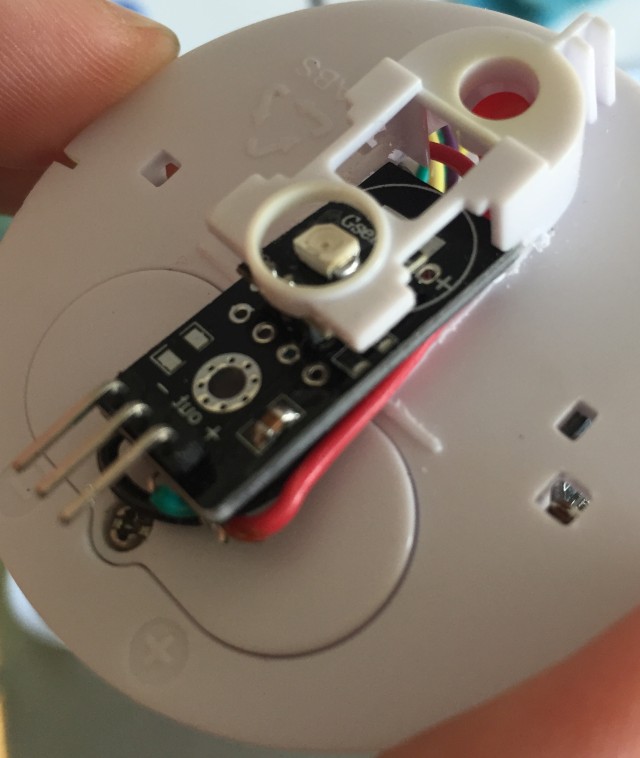
    To get things in the housing I had to desolder the main piece from the UV sensor. Things have gone wrong from here because after that the sensor did not work anymore. Probably fried the sensor?! New one is on its way.
    So I must think of another way to get the sensor in place at the top of the housing. There not enough place so I must be creative and not destroying another sensor!

    I also would like to share a short piece of code I found to test the uv sensors output. This way you don't need to attach all the radio wires to see if the sensor is working.

    /*

    This Sample code is for testing the UV Sensor .

    #Connection:
    VCC-5V
    GND-GND
    OUT-Analog pin 0
    */

    void setup()
    {
    Serial.begin(9600);// open serial port, set the baud rate to 9600 bps
    }
    void loop()
    {
    int sensorValue;
    sensorValue = analogRead(0);//connect UV sensors to Analog 0
    Serial.println(sensorValue);//print the value to serial
    delay(200);
    }

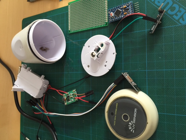
    The pieces on the table:
    IMG_0353.JPG

    New sensor arrived and bought a 15W soldering iron.

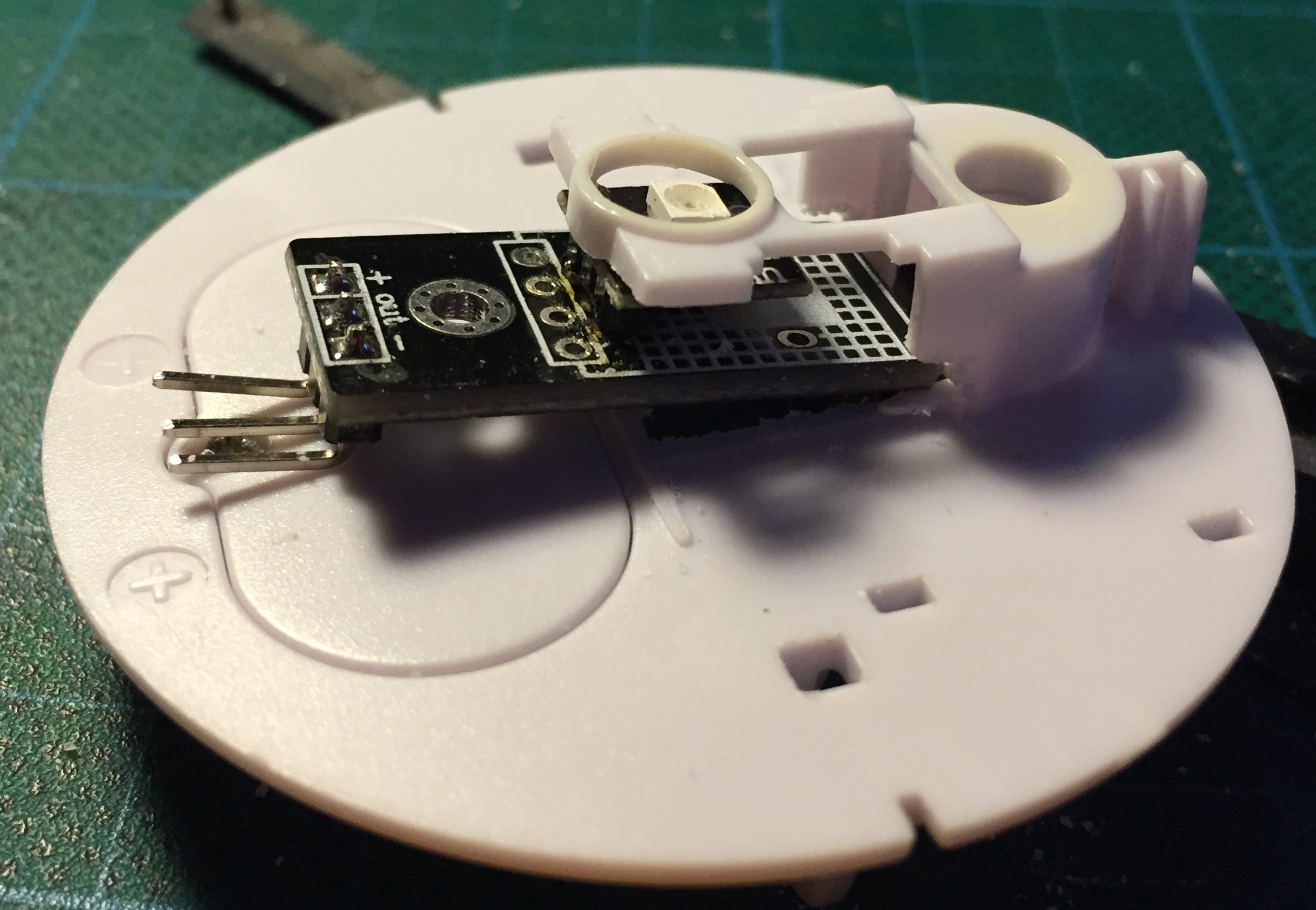
    Puting things together and make some room for the sensor board

    20150526_190923284_iOS.jpg

    20150529_181320010_iOS.jpg

    20150613_133448340_iOS.jpg

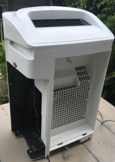
    After everthing was put in place the sensor went outside for testing.
    For reference I also used a nearby UV sensor via Weather Underground.

    20150615_150304000_iOS.png

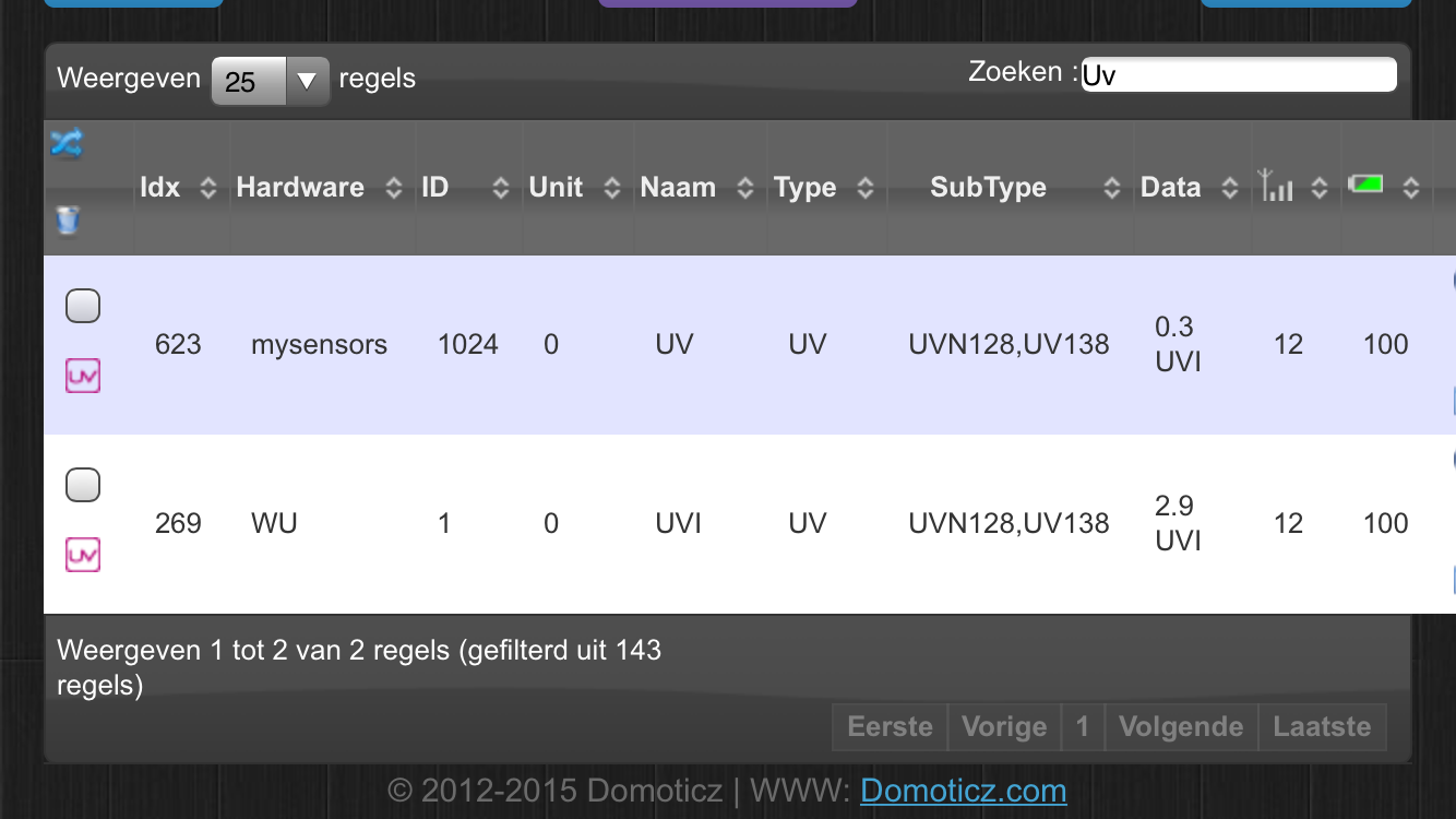
    At first everything looked fine but it seems that the measurements from my sensor are to low.
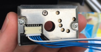
    I removed the sensor and did some testing with the above sketch to measure the output voltage on 3.3v and 5v but the results were the samen and to low.
    Does anyone know what can cause this low measurement ? checked the wires. checked the sketch. replaced the arduino board.
    Another broken sensor?

    My Project

  • Watertank empty notification for sharp air purifiers (Sharp KC-A50EUW & KCA40EUW)
    E edweather

    We have two Sharp air purifiers - KC-A50EUW & KC-A40EUW - with humidifying function.
    6066a6c1-e8c8-4aab-9926-5e21c87e019f-image.png

    They do their job very well but if the watertank runs empty this gives a terrible smell because the humidify filter runs dry.
    Don't know why it smells so bad but must be some kind of biological reaction.

    5bbe510f-7d3b-4564-ae14-4e2d6c2b057d-image.png

    Because of their function of cleaning the air these devices require periodic maintenance. Clean the airfilters, soak the humdifying filter and other parts in citric acid to decalc.
    It's also a great dust collector and that dust also getting inside the appliance at places you can't easily reach.
    So I dicided to take one of the devices apart to clean the inside.

    e84cdb15-8cfc-4344-9d6d-01c46b02cd38-image.png
    As you can see the dust is everywhere.

    Getting inside the device is verry easy, just unscrew the screws and that's it.
    On the inside of both devices there are some familiar parts like the Sharp GP2Y1010AU0F dust sensor.
    40aa1289-3503-4358-aaa9-2626d068dbe5-image.png
    The gas/smell sensor differs in each appliance as I found out when servicing the other device later.

    c26b82ba-51e3-4b91-9219-0fffb6c31d85-image.pngKC-A40EUW

    976a0ab9-1ce7-486d-b645-7fd04cddeed5-image.png KC-A50EUW

    If the watertank runs empty there is a floater with a small magnet that triggers a contact and turns on a notification light on the front of the device.
    5ee9d60f-480c-4c90-962a-12f5bb702c3f-image.png
    1b67adf9-8a14-445c-ab7b-07bb398545f2-image.png

    This started me thinking of an easy hack to just add a contact sensor near the orignal sensor.
    b8e44472-c7e4-4bd0-b723-dbd0c3712c45-image.png
    So that's what I did and it worked instanly. On the kc-a50euw I had to shorten the contact just a little to make it fit.

    I borrowed 5v power from the applicance itself and used the glue gun(no image of that) to cover my solder points.
    3828cc13-a88b-48b9-85c7-86ea6a728b0d-image.png

    On the main board of the device there were some interesting connections but I did not dare to hook them up to a serial monitor.
    Would like to investigate this later with some help of more skilled techies.

    33d64071-001e-4866-86c4-3ac2168351c6-image.png

    After this it was easy to get the appliance show up in my Homeassistant setup.
    52449521-5898-4626-b47a-7547494e065d-image.png
    If the watertank runs empty it shows up in Homeassistant and with an automation setup I will receive a message on my phone to fill the tank.
    Turning the device off is also an option (when youre not home) just add a smart plug in the mix!

    I used the the default contact sensor script from the mysensors website and changed it a little to get it working with homeassistant.

    Because SKETCH_NAME and SKETCH_VERSION were missing it did not work in HA
    also added #define MY_RF24_PA_LEVEL (RF24_PA_MAX) because of reception issues.
    I put the radio to close to the electric parts I think.

    Other changes:
    #define MY_NODE_ID 6
    #define MY_REPEATER_FEATURE

    In HomeAssistant I changed the device class of the entity from 'door' to 'problem'
    6411371b-113a-4b67-891f-42784de84f14-image.png

    I hope you liked my project as much as I do and that it inspires you.

    The code:

    /**
     * The MySensors Arduino library handles the wireless radio link and protocol
     * between your home built sensors/actuators and HA controller of choice.
     * The sensors forms a self healing radio network with optional repeaters. Each
     * repeater and gateway builds a routing tables in EEPROM which keeps track of the
     * network topology allowing messages to be routed to nodes.
     *
     * Created by Henrik Ekblad <henrik.ekblad@mysensors.org>
     * Copyright (C) 2013-2015 Sensnology AB
     * Full contributor list: https://github.com/mysensors/Arduino/graphs/contributors
     *
     * Documentation: http://www.mysensors.org
     * Support Forum: http://forum.mysensors.org
     *
     * This program is free software; you can redistribute it and/or
     * modify it under the terms of the GNU General Public License
     * version 2 as published by the Free Software Foundation.
     *
     *******************************
     *
     * DESCRIPTION
     *
     * Simple binary switch example 
     * Connect button or door/window reed switch between 
     * digitial I/O pin 3 (BUTTON_PIN below) and GND.
     * http://www.mysensors.org/build/binary
     */
    
    // General settings
    #define SKETCH_NAME "luchtreiniger-woonkamer"
    #define SKETCH_VERSION "1.0"
    #define MY_NODE_ID 6
    
    #define MY_REPEATER_FEATURE
    
    // Enable debug prints to serial monitor
    //#define MY_DEBUG 
    
    // Enable and select radio type attached
    #define MY_RADIO_RF24
    #define MY_RF24_PA_LEVEL (RF24_PA_MAX) //reception issues because the radio is to close to electric parts
    
    #include <MySensors.h>
    #include <Bounce2.h>
    
    #define CHILD_ID 3
    #define BUTTON_PIN  3  // Arduino Digital I/O pin for button/reed switch
    
    Bounce debouncer = Bounce(); 
    int oldValue=-1;
    
    // Change to V_LIGHT if you use S_LIGHT in presentation below
    MyMessage msg(CHILD_ID,V_TRIPPED);
    
    void setup()  
    {  
      // Setup the button
      pinMode(BUTTON_PIN,INPUT);
      // Activate internal pull-up
      digitalWrite(BUTTON_PIN,HIGH);
    
      // After setting up the button, setup debouncer
      debouncer.attach(BUTTON_PIN);
      debouncer.interval(5);
    
    }
    
    void presentation() {
      // Register binary input sensor to gw (they will be created as child devices)
      // You can use S_DOOR, S_MOTION or S_LIGHT here depending on your usage. 
      // If S_LIGHT is used, remember to update variable type you send in. See "msg" above.
      sendSketchInfo(SKETCH_NAME, SKETCH_VERSION);
      present(CHILD_ID, S_DOOR);  
    }
    
    //  Check if digital input has changed and send in new value
    void loop() 
    {
      debouncer.update();
      // Get the update value
      int value = debouncer.read();
    
      if (value != oldValue) {
         // Send in the new value
         send(msg.set(value==HIGH ? 1 : 0));
         oldValue = value;
      }
    }
    
    My Project homeassistant contact air quality water
  • Login

  • Don't have an account? Register

  • Login or register to search.
  • First post
    Last post
0
  • MySensors
  • OpenHardware.io
  • Categories
  • Recent
  • Tags
  • Popular