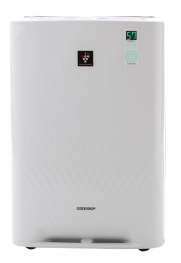
We have two Sharp air purifiers - KC-A50EUW & KC-A40EUW - with humidifying function.
They do their job very well but if the watertank runs empty this gives a terrible smell because the humidify filter runs dry.
Don't know why it smells so bad but must be some kind of biological reaction.
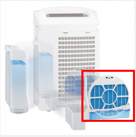
Because of their function of cleaning the air these devices require periodic maintenance. Clean the airfilters, soak the humdifying filter and other parts in citric acid to decalc.
It's also a great dust collector and that dust also getting inside the appliance at places you can't easily reach.
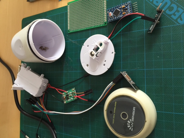
So I dicided to take one of the devices apart to clean the inside.
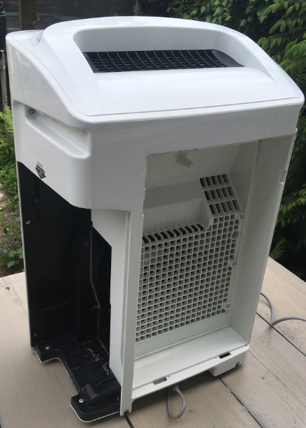
As you can see the dust is everywhere.
Getting inside the device is verry easy, just unscrew the screws and that's it.
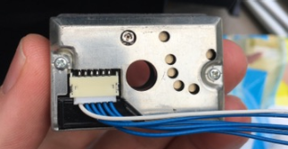
On the inside of both devices there are some familiar parts like the Sharp GP2Y1010AU0F dust sensor.
The gas/smell sensor differs in each appliance as I found out when servicing the other device later.
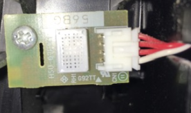
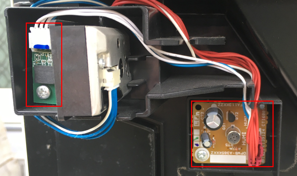
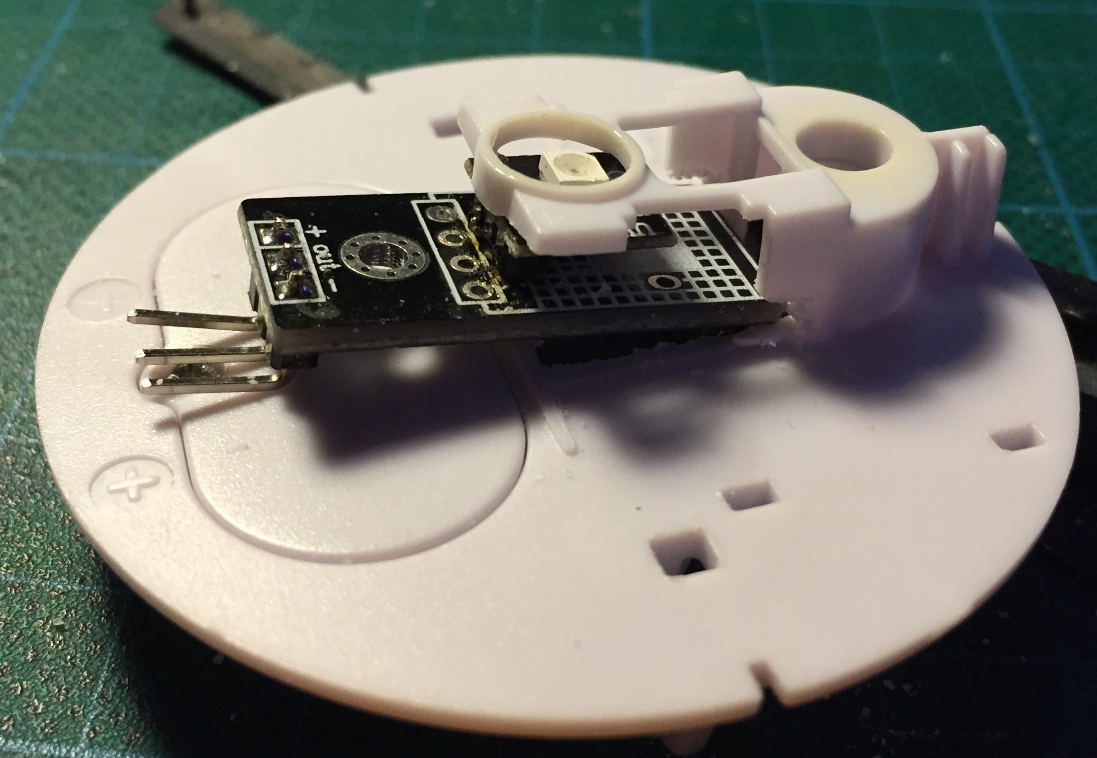
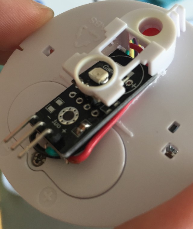
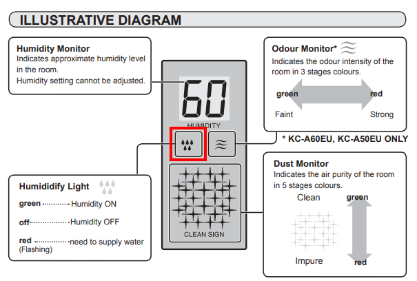
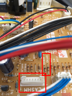
If the watertank runs empty there is a floater with a small magnet that triggers a contact and turns on a notification light on the front of the device.
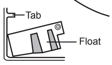
This started me thinking of an easy hack to just add a contact sensor near the orignal sensor.
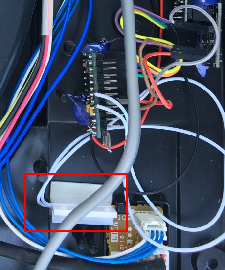
So that's what I did and it worked instanly. On the kc-a50euw I had to shorten the contact just a little to make it fit.
I borrowed 5v power from the applicance itself and used the glue gun(no image of that) to cover my solder points.
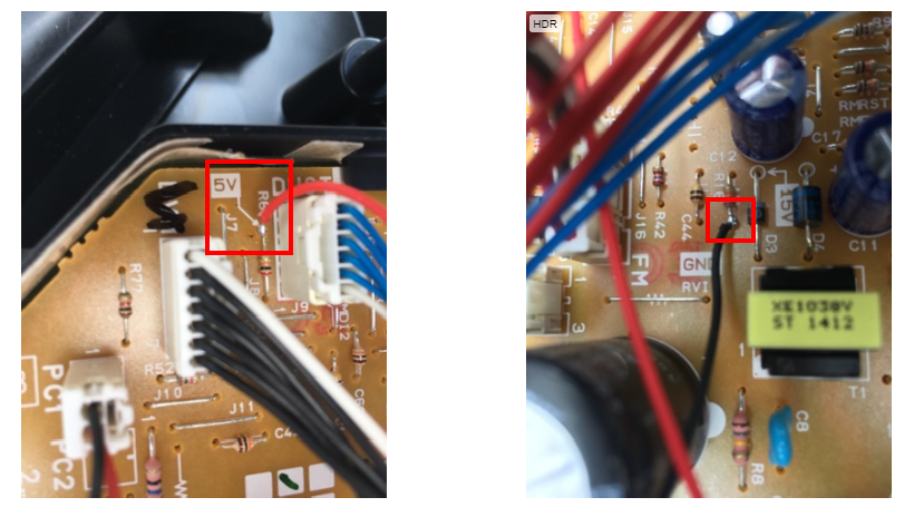
On the main board of the device there were some interesting connections but I did not dare to hook them up to a serial monitor.
Would like to investigate this later with some help of more skilled techies.
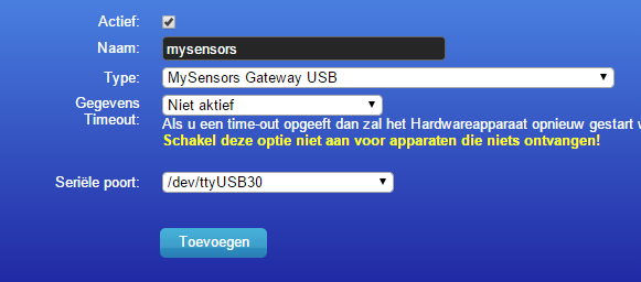
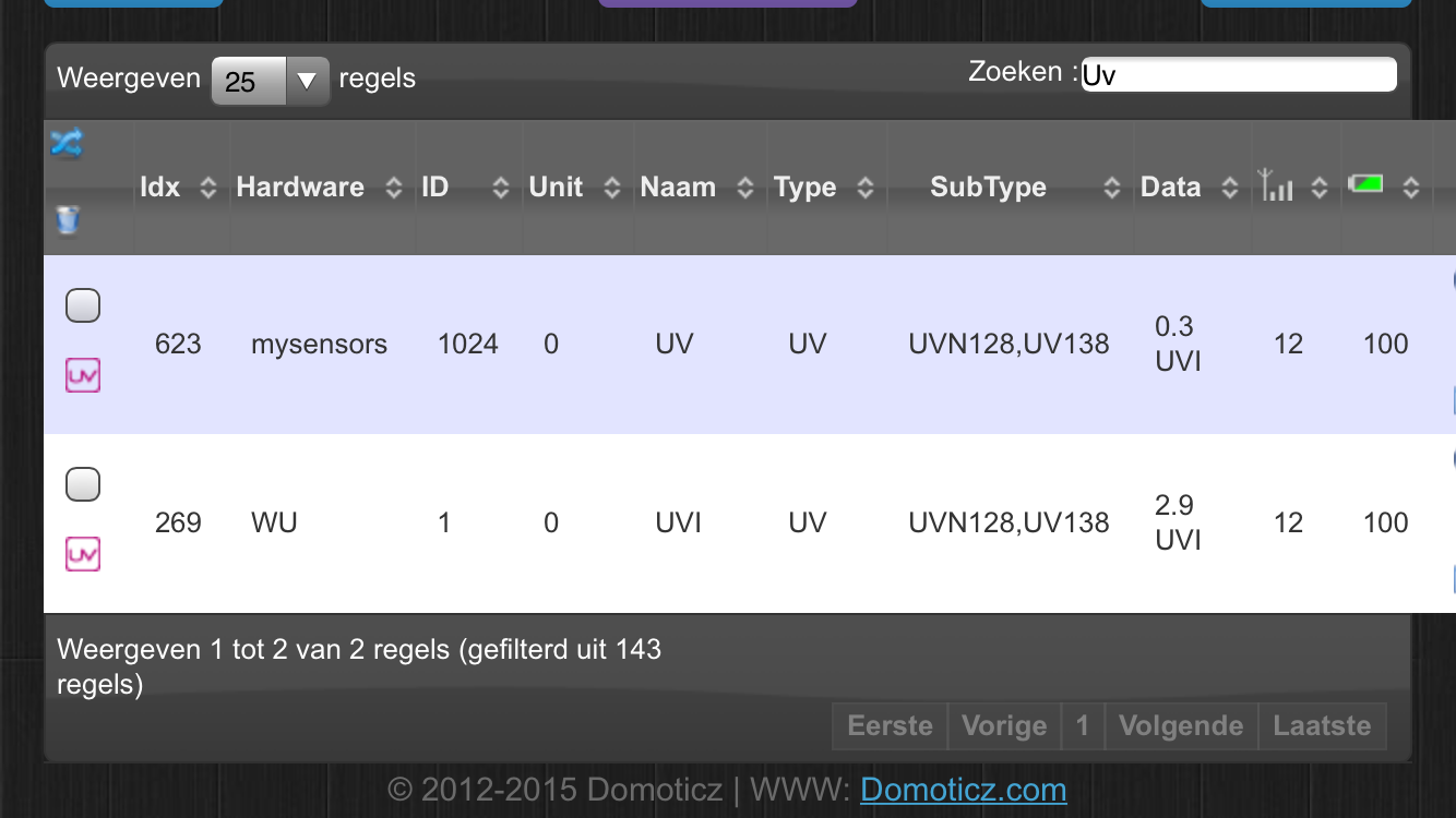
After this it was easy to get the appliance show up in my Homeassistant setup.
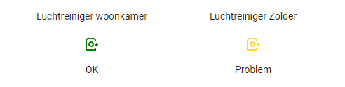
If the watertank runs empty it shows up in Homeassistant and with an automation setup I will receive a message on my phone to fill the tank.
Turning the device off is also an option (when youre not home) just add a smart plug in the mix!
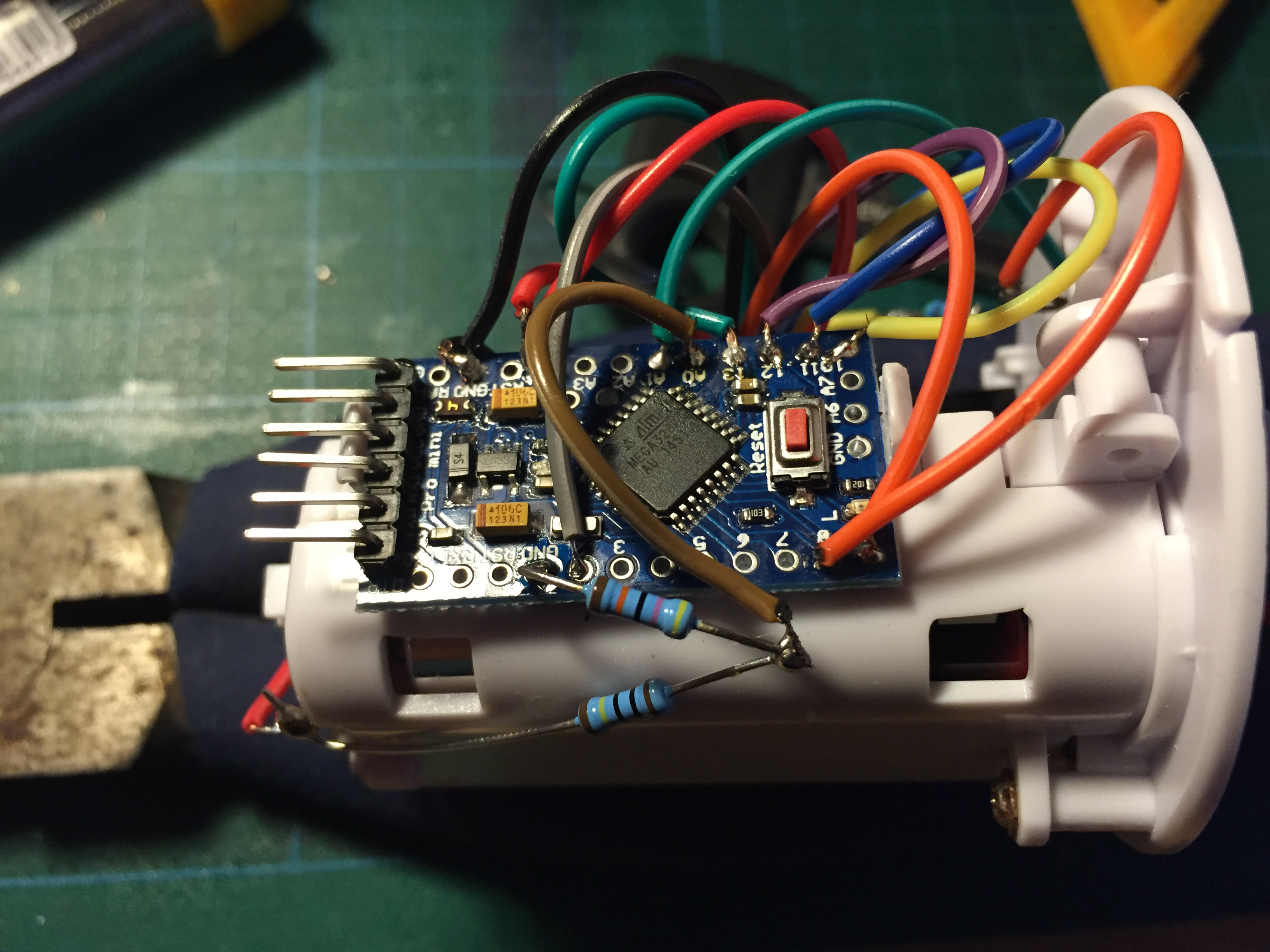
I used the the default contact sensor script from the mysensors website and changed it a little to get it working with homeassistant.
Because SKETCH_NAME and SKETCH_VERSION were missing it did not work in HA
also added #define MY_RF24_PA_LEVEL (RF24_PA_MAX) because of reception issues.
I put the radio to close to the electric parts I think.
Other changes:
#define MY_NODE_ID 6
#define MY_REPEATER_FEATURE
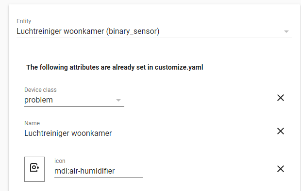
In HomeAssistant I changed the device class of the entity from 'door' to 'problem'
I hope you liked my project as much as I do and that it inspires you.
The code:
/**
 * The MySensors Arduino library handles the wireless radio link and protocol
 * between your home built sensors/actuators and HA controller of choice.
 * The sensors forms a self healing radio network with optional repeaters. Each
 * repeater and gateway builds a routing tables in EEPROM which keeps track of the
 * network topology allowing messages to be routed to nodes.
 *
 * Created by Henrik Ekblad <henrik.ekblad@mysensors.org>
 * Copyright (C) 2013-2015 Sensnology AB
 * Full contributor list: https://github.com/mysensors/Arduino/graphs/contributors
 *
 * Documentation: http://www.mysensors.org
 * Support Forum: http://forum.mysensors.org
 *
 * This program is free software; you can redistribute it and/or
 * modify it under the terms of the GNU General Public License
 * version 2 as published by the Free Software Foundation.
 *
 *******************************
 *
 * DESCRIPTION
 *
 * Simple binary switch example
 * Connect button or door/window reed switch between
 * digitial I/O pin 3 (BUTTON_PIN below) and GND.
 * http://www.mysensors.org/build/binary
 */

// General settings
#define SKETCH_NAME "luchtreiniger-woonkamer"
#define SKETCH_VERSION "1.0"
#define MY_NODE_ID 6

#define MY_REPEATER_FEATURE

// Enable debug prints to serial monitor
//#define MY_DEBUG

// Enable and select radio type attached
#define MY_RADIO_RF24
#define MY_RF24_PA_LEVEL (RF24_PA_MAX) //reception issues because the radio is to close to electric parts

#include <MySensors.h>
#include <Bounce2.h>

#define CHILD_ID 3
#define BUTTON_PIN  3  // Arduino Digital I/O pin for button/reed switch

Bounce debouncer = Bounce();
int oldValue=-1;

// Change to V_LIGHT if you use S_LIGHT in presentation below
MyMessage msg(CHILD_ID,V_TRIPPED);

void setup()
{
  // Setup the button
  pinMode(BUTTON_PIN,INPUT);
  // Activate internal pull-up
  digitalWrite(BUTTON_PIN,HIGH);

  // After setting up the button, setup debouncer
  debouncer.attach(BUTTON_PIN);
  debouncer.interval(5);

}

void presentation() {
  // Register binary input sensor to gw (they will be created as child devices)
  // You can use S_DOOR, S_MOTION or S_LIGHT here depending on your usage.
  // If S_LIGHT is used, remember to update variable type you send in. See "msg" above.
  sendSketchInfo(SKETCH_NAME, SKETCH_VERSION);
  present(CHILD_ID, S_DOOR);
}

//  Check if digital input has changed and send in new value
void loop()
{
  debouncer.update();
  // Get the update value
  int value = debouncer.read();

  if (value != oldValue) {
     // Send in the new value
     send(msg.set(value==HIGH ? 1 : 0));
     oldValue = value;
  }
}
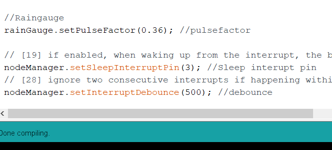
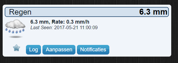
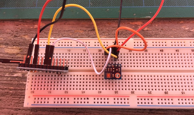 image url)