G
gigi
@gigi
Posts
-
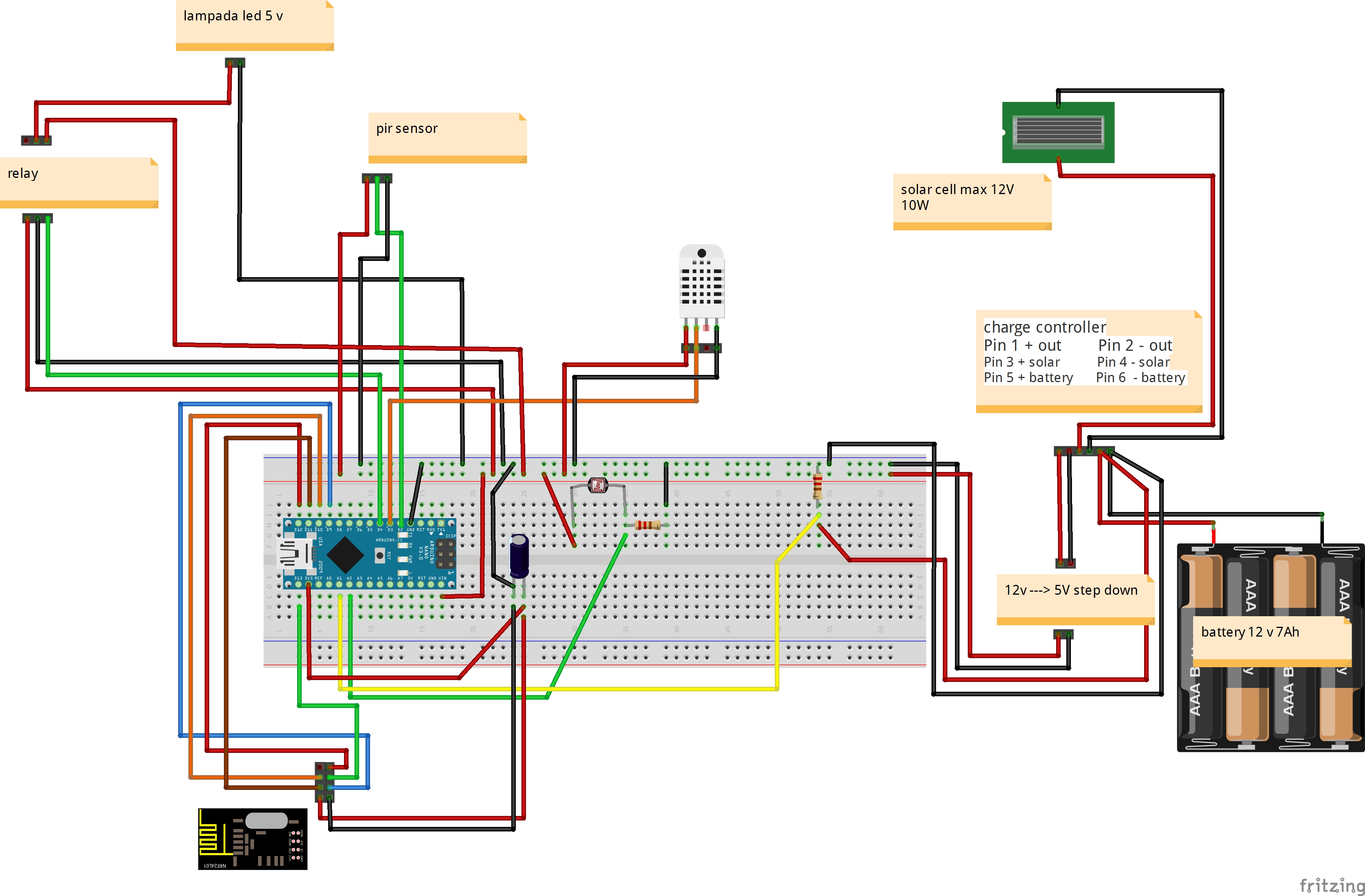
Solar Powered Mini-Weather Station -
Solar Powered Mini-Weather Station@Petjepet said:
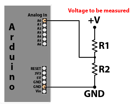
On the green wire (light sensor?) you measure on ground where I guess you should measure between the resistor and the sensor.
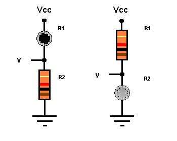
Is the same
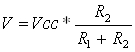
voltage divider
-
Solar Powered Mini-Weather Station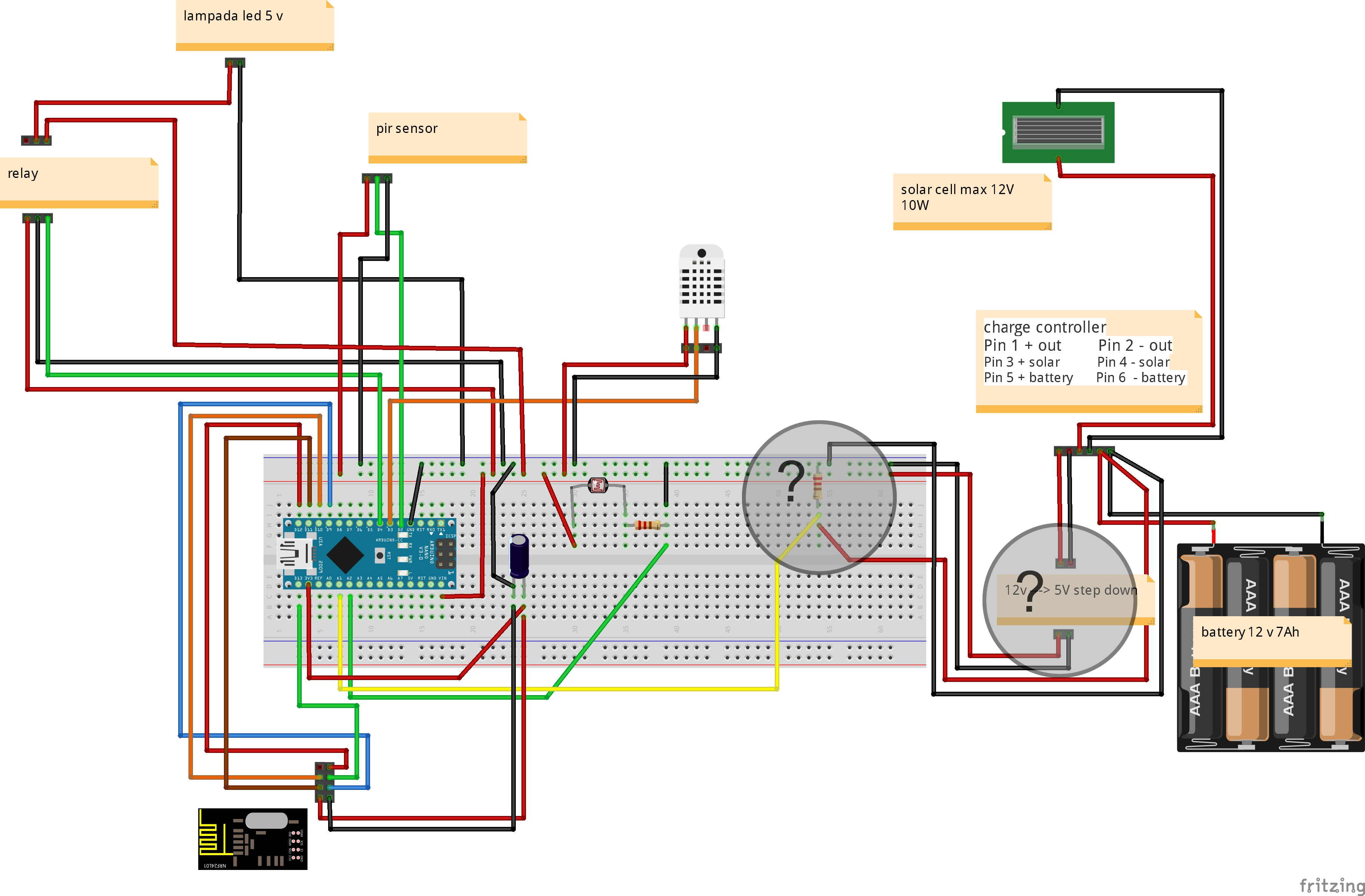
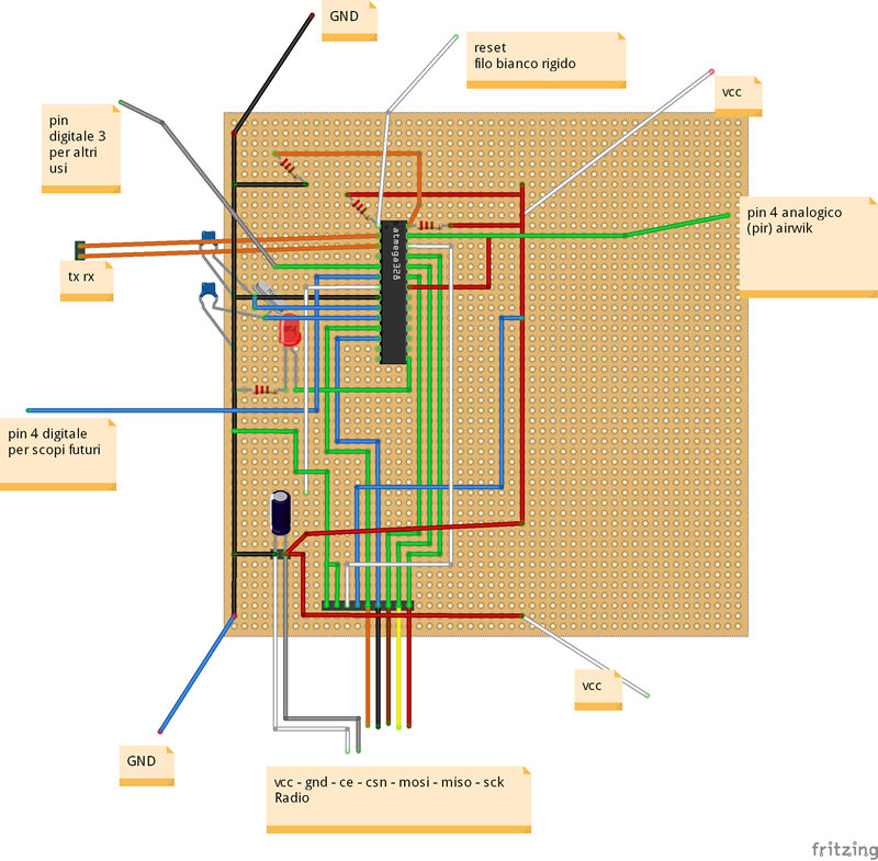
New fritzing
I have two questions?
- voltage divider for more 5 v (battery voltage 12-13 volts)
- I use a auto phone charger for step down (12v --> 5 V) - warmers if I close in a box?
Thank
-
Solar Powered Mini-Weather Station@Didi 0_1459967939633_schema-pannello-solare-2.fzz
Fritzing File!!!!
-
Solar Powered Mini-Weather Station@Dombo71 look a fritzing schematic
-
Solar Powered Mini-Weather StationI purchased a solar kit
Solar Panel
battery 12v
landstar solar charge controllerI want to insert into Arduino in output of charge controller (I have 12 volts)
to lower the voltage can I use a mobile charger Car 1 Ah
do you heat so much?
Thank
@Salmoides Good Project!!!!!
-
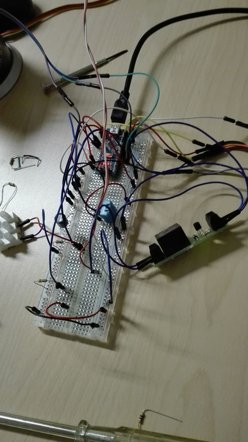
Solar Powered Mini-Weather StationThis is my project!!!!
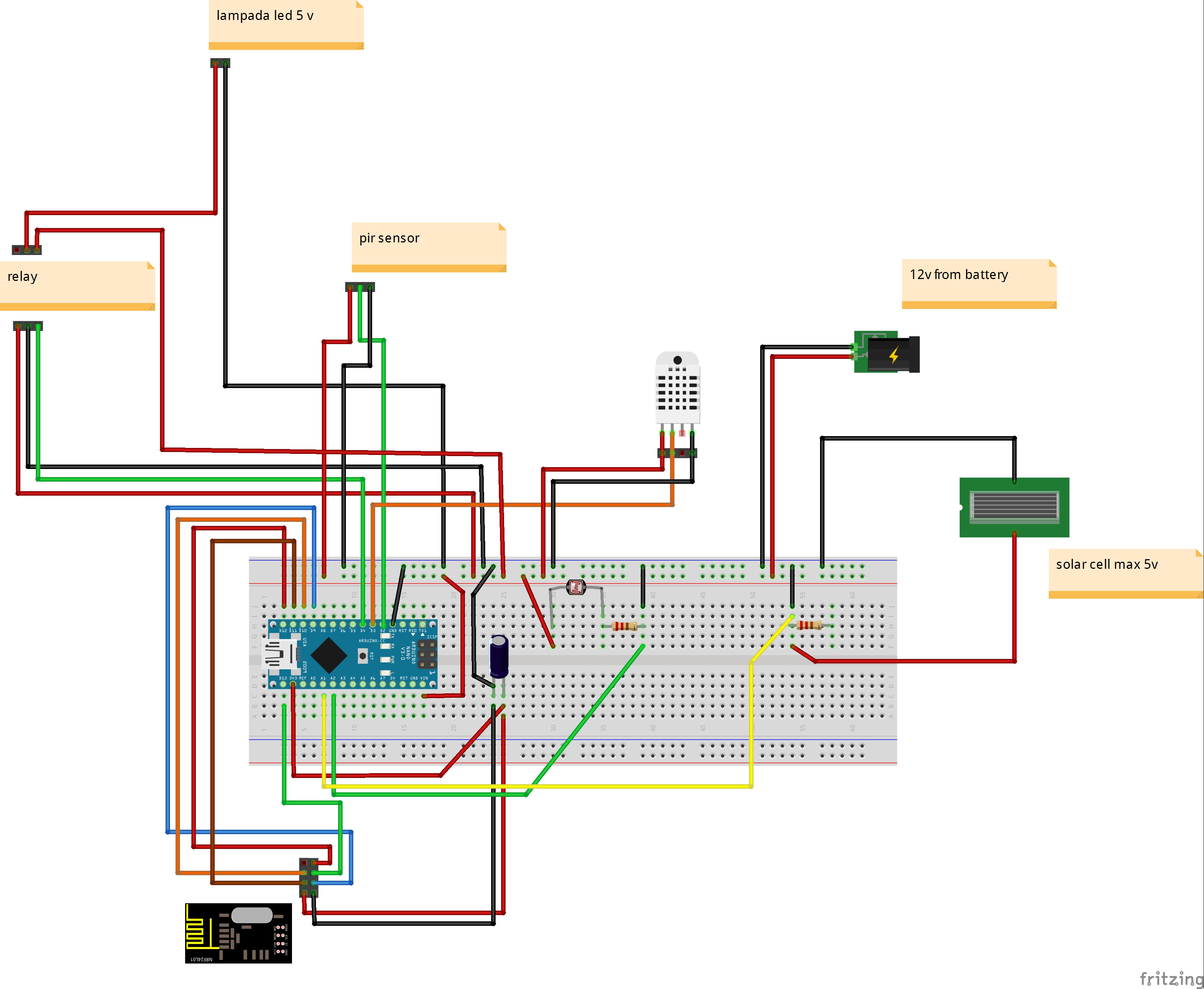
// Example sketch för a "light switch" where you can control light or something
// else from both vera and a local physical button (connected between digital
// pin 3 and GND).
// This node also works as a repeader for other nodes

#include <MySensor.h>
#include <SPI.h>
#include <DHT.h>

unsigned long SLEEP_TIME = 120000; // Sleep time between reports (in milliseconds)

//pin sensori
#define PIR_PIN 2                   // The digital input you attached your motion sensor.  (Only 2 and 3 generates interrupt!)
#define HUMIDITY_TEMPERATURE_PIN 3  // sensore temperatura umidita
#define RELAY_PIN  4                // relay pin
int BATTERY_SENSE_PIN = A1;         // Pin carica batteria o pannello solare
int FOTORESIST_SENSE_PIN = A2;      // Pin fotoresistenza

//interupt per sleep arduino
#define INTERRUPT PIR_PIN-2 // Usually the interrupt = pin -2 (on uno/nano anyway)

//id per vera
#define CHILD_ID_RELE 1   // Id relay
#define CHILD_ID_HUM 2    // id temperatura
#define CHILD_ID_TEMP 3   // id umidita
#define CHILD_ID_PIR 4    // Id pir
#define CHILD_ID_LIGHT 5  // Id luminosita (fotoresistenza)

//definizione per nodo vera
#define NODE_ID 10
#define SN "meteo station"
#define SV "1.4"

//variabili
bool state_relay;                 //stato relay
float batt_valore;                //dichiaro la variabile valore che memorizzerà il valore della batteria dal pin analogico
float batt_volt;                  //volt batteria
float batt_charged_percent;       //percentuale carica batteria
float last_batt_charged_percent;  //percentuale carica batteria precedente
float batt_min_voltage = 0.5;     //tensione minima batteria
float batt_max_voltage = 5;       //tensione massima batteria
float fotoresistenza_valore;      //dichiaro la variabile valore che memorizzerà il valore della fotoresistenza dal pin analogico
float last_fotoresistenza_valore; //dichiaro la variabile valore precedente

int lux_vera;                      //valore luminosita da inviare a vera

MySensor gw;

// sensore temperatura umidita
DHT dht_int;
float lastTemp_int = -1;
float lastHum_int = -1;

boolean metric = true;

MyMessage msgRelay(CHILD_ID_RELE,V_LIGHT);
MyMessage msgHum(CHILD_ID_HUM, V_HUM);
MyMessage msgTemp(CHILD_ID_TEMP, V_TEMP);
MyMessage msgPir(CHILD_ID_PIR, V_TRIPPED);
MyMessage msgLux(CHILD_ID_LIGHT, V_LIGHT_LEVEL);

void setup()
{
  gw.begin(incomingMessage, NODE_ID, false);

  gw.sendSketchInfo(SN, SV);

  //Sensore umidita temperatura
  dht_int.setup(HUMIDITY_TEMPERATURE_PIN);

  gw.present(CHILD_ID_RELE, S_LIGHT);       //light vera
  gw.present(CHILD_ID_HUM, S_HUM);          //umidity vera
  gw.present(CHILD_ID_TEMP, S_TEMP);           // temp vera
  gw.present(CHILD_ID_PIR, S_MOTION);          // motion vera
  gw.present(CHILD_ID_LIGHT, S_LIGHT_LEVEL);  //light level (fotoresistenza)

  metric = gw.getConfig().isMetric;

  // Then set relay pins in output mode
  pinMode(RELAY_PIN, OUTPUT);

  //PIR
  pinMode(PIR_PIN, INPUT);

  state_relay = 0;
  //GestisciRelay();
  digitalWrite(RELAY_PIN, LOW);
  gw.send(msgRelay.set(state_relay));

}

void loop()
{
    gw.process();

    //sensore temperatura umidita
    delay(dht_int.getMinimumSamplingPeriod());

    float temperature_int = dht_int.getTemperature();
    if (isnan(temperature_int))
    {
        lastTemp_int = -1;
        Serial.println("Failed reading temperature from DHT");
    }
    else if (temperature_int != lastTemp_int)
    {
      lastTemp_int = temperature_int;
      if (!metric)
      {
        temperature_int = dht_int.toFahrenheit(temperature_int);
      }
      gw.send(msgTemp.set(temperature_int, 1));
      Serial.print("T int: ");
      Serial.println(temperature_int);
    }

    float humidity_int = dht_int.getHumidity();
    if (isnan(humidity_int))
    {
        lastHum_int = -1;
        Serial.println("Failed reading humidity from DHT");
    }
    else if (humidity_int != lastHum_int)
    {
        lastHum_int = humidity_int;
        gw.send(msgHum.set(humidity_int, 1));
        Serial.print("H int: ");
        Serial.println(humidity_int);
    }
    //sensore temperatura umidita

    //fotoresistenza
    for(int i=0;i<150;i++)
    {
      fotoresistenza_valore += analogRead(FOTORESIST_SENSE_PIN);  //read the input voltage from battery or solar panel
      delay(2);
    }
    fotoresistenza_valore = fotoresistenza_valore / 150;

    Serial.print ("fotoresistenza: ");
    Serial.println(fotoresistenza_valore);

    if (fotoresistenza_valore != last_fotoresistenza_valore)
    {
      lux_vera = (int) fotoresistenza_valore;
      gw.send(msgLux.set(lux_vera));
      last_fotoresistenza_valore = fotoresistenza_valore;
    }
    //fotoresistenza

    //pir relay
    // Read digital motion value
    boolean tripped = digitalRead(PIR_PIN) == HIGH;
    Serial.println("pir:");
    Serial.println(tripped);
    gw.send(msgPir.set(tripped?"1":"0"));  // Send tripped value to gw

    //accende la luce con il buio
    if (fotoresistenza_valore < 200)  //poca luce
    {
      if (tripped == 1)
      {
         state_relay = 1;
      }
      else
      {
         state_relay = 0;
      }
    }
    //accende la luce con il buio

    GestisciRelay();
    //pir relay

    //battery
    for(int i=0;i<150;i++)
    {
      batt_valore += analogRead(BATTERY_SENSE_PIN);  //read the input voltage from battery or solar panel
      delay(2);
    }
    batt_valore = batt_valore / 150;

    Serial.print ("batt_valore: ");
    Serial.println(batt_valore);

    batt_volt = (batt_valore / 1024) * batt_max_voltage;
    Serial.print ("batt_volt: ");
    Serial.println(batt_volt);

    ////////////////////////////////////////////////
   //The map() function uses integer math so will not generate fractions
   // so I multiply battery voltage with 10 to convert float into a intiger value
   // when battery voltage is 6.0volt it is totally discharged ( 6*10 =60)
   // when battery voltage is 7.2volt it is fully charged (7.2*10=72)
   // 6.0v =0% and 7.2v =100%
   //batt_charged_percent = batt_volt*10;
   //batt_charged_percent = map(batt_volt*10, 60 , 72, 0, 100);
    batt_charged_percent = batt_volt * 10;
    batt_charged_percent = map(batt_volt * 10, batt_min_voltage * 10 , batt_max_voltage * 10, 0, 100);
    //batt_charged_percent = (batt_volt / batt_max_voltage) * 100;
    Serial.print ("batt_charged_percent: ");
    Serial.println(batt_charged_percent);

    if (last_batt_charged_percent != batt_charged_percent)
    {
        gw.sendBatteryLevel(batt_charged_percent);
        last_batt_charged_percent = batt_charged_percent;
    }
    //battery

    delay(50);

    // Sleep until interrupt comes in on motion sensor. Send update every two minute.
    gw.sleep(INTERRUPT, CHANGE, SLEEP_TIME);


}

void incomingMessage(const MyMessage &message) {
  // We only expect one type of message from controller. But we better check anyway.
  if (message.isAck()) {
     Serial.println("This is an ack from gateway");
  }

  if (message.type == V_LIGHT) {
     // Change relay state_relay
     state_relay = message.getBool();
     GestisciRelay();

     // Write some debug info
     Serial.print("Incoming change for sensor:");
     Serial.print(message.sensor);
     Serial.print(", New status: ");
     Serial.println(message.getBool());
   }


}


void GestisciRelay()
{
    //Serial.print(" GestisciRelay state_relay:");
    //Serial.println(state_relay);

    if (state_relay == 0)
    {
      digitalWrite(RELAY_PIN, LOW);
      gw.send(msgRelay.set(state_relay));
      //Serial.println("SPENTO RELAY");
    }
    else
   {
      digitalWrite(RELAY_PIN, HIGH);
      gw.send(msgRelay.set(state_relay));
      //Serial.println("ACCESO RELAY");
   }


}
On vera
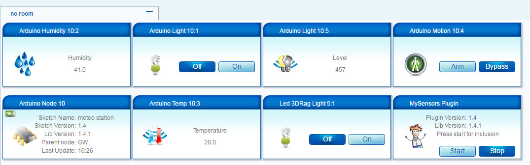
On board
-
Merry Christmas and a Happy New 2016Merry Christmas
-
Gateway not working on VeraLite + UI6 - No Serial Port configuration available@cdrum I tried with many arduino nano purchased on ebay but I could not connect on vera.
Try with gateway Ethernet !!!
-
[security] Introducing signing support to MySensors@Anticimex very nice work.
-
[contest] My GatewayI have created a bridge for mysensors and openenergymonitor, Openenrgymonitor work whith respberry and emoncms. Whit this way I can save the data of sensor data mysensors.
Node 7 is bridge to mysensors and RFM12B radio.
radio transmission is point to point!!! -
IR Sensor@Terence-Faul which controller do you have?
-
[contest] BcSensorhow do you make these pcb so beautiful?
my pcb are full of wires !!!
-
Multi Button Relay switchthere is no problem to put 4 relays.
you just feed a separate power!!! -
Sensor to control remote controlled switches from Flamingo.eu e.g. mumbi m-FS300@Heinz nice project !!!
I use VERA, I did a My Relay Module, if I push button or send command on vera, i have alwais a state of socket.
with your system, you can know the status of the socket?
from the photo, I dont' see a button to turn on the socket !!!! Only via remote control!!!
gigi
-
Small wall outlet sensor node@axillent
very very cool!! -
External power supply to radio@ServiceXp said:
I just can't believe that the display, rfm12b and NRF24 on the same 3.3v rail is under 50ma,... not too mention the other stuff on it.. You could try disconnecting everything except the NRF24 and see what happens?
I can't even get my NRF24's to work with the shop's listed boost with the Pro Mini attached without a 'massive' capacitor.
I tried to put a separate power supply.
General supply 5V 2 Amps.
I do not have the controller and I put two arduino nano for 3.3 volts
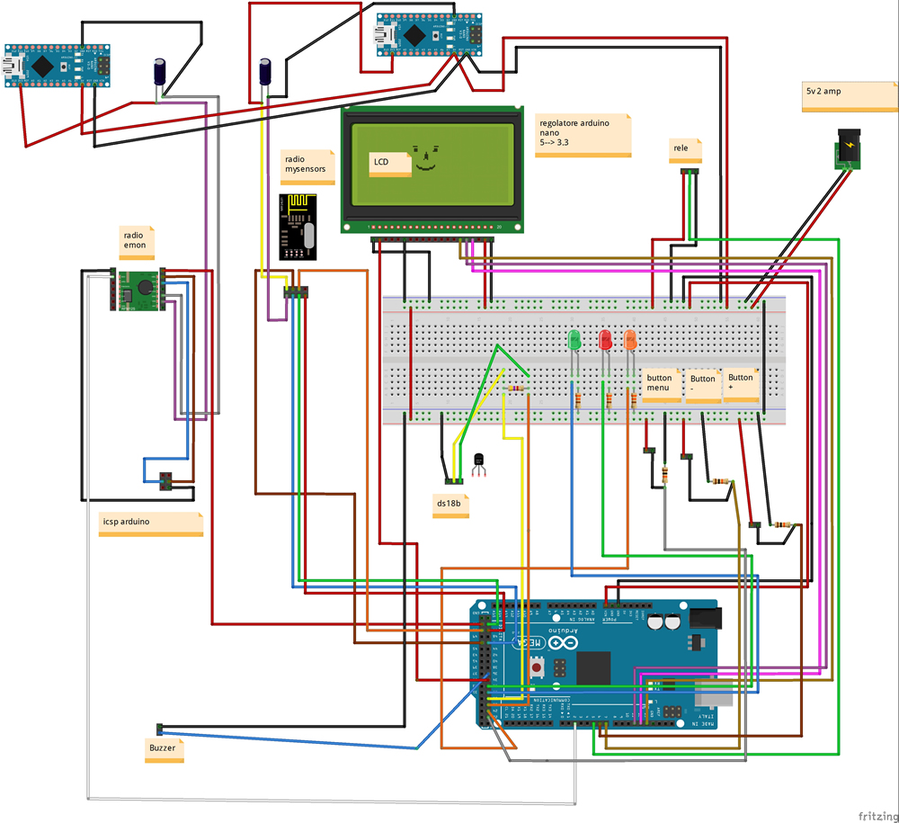
after 2 hours the system crashes.
if I put only one of the two radio system is fine.
I tried it with a standalone with two radio but without a monitor and the system works perfectly!!!
I have to put other capacitors?
Thank
-
MyAirwik Sensor@gregl said:
haha..cool.
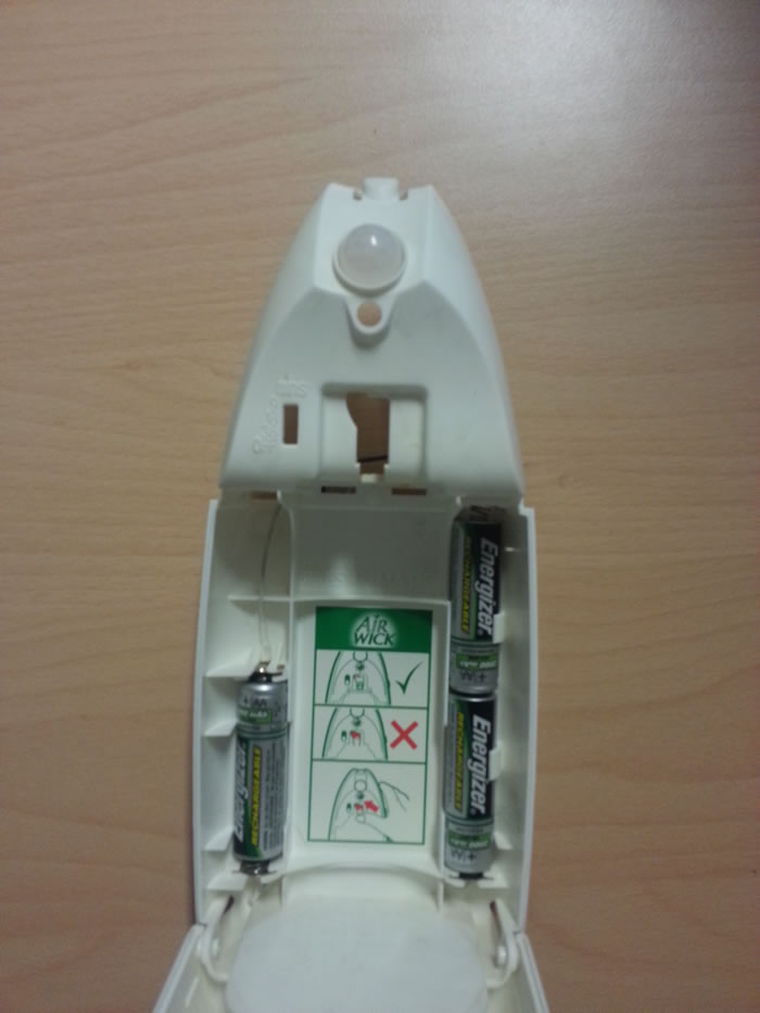
I bought an airwik like clone the other day, but i want to hack in a pir sensor so that it only squirts the airfreshner when movement is detected and use mysensors to count how many squirts it does....so as to know when to replace can.
now i think about it, i should have bought one with a pir inbuilt like yours...oh well!
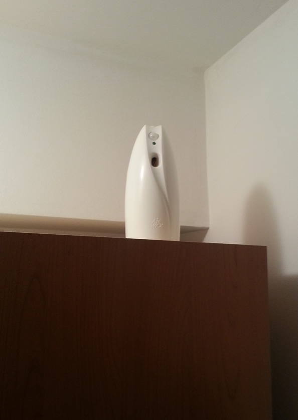
watch this photo!!!
-
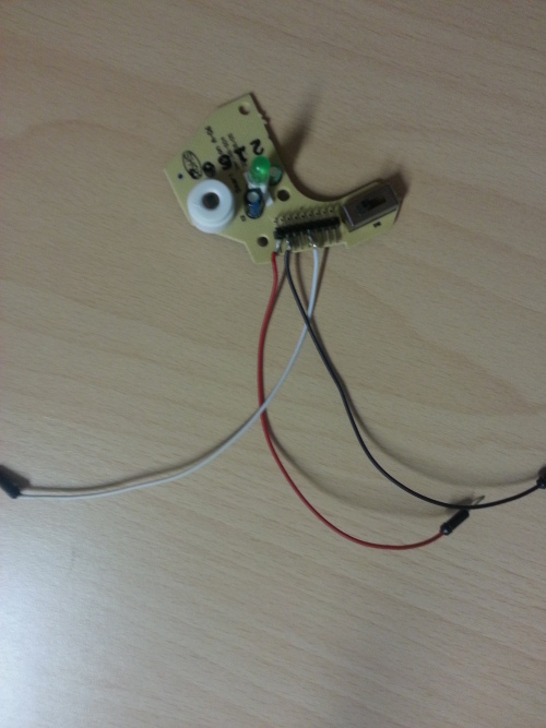
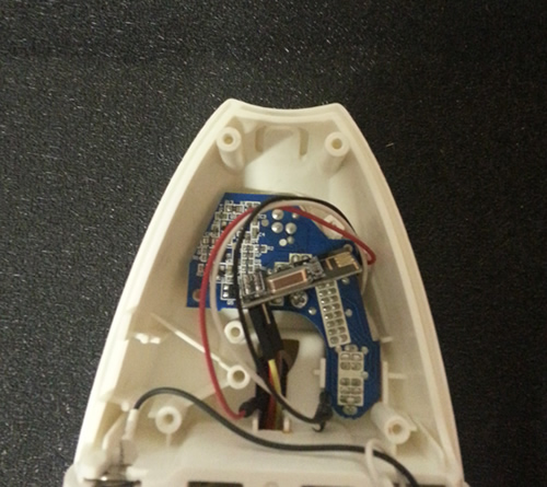
MyAirwik SensorHay!!!
This is MyAirwik Sensor
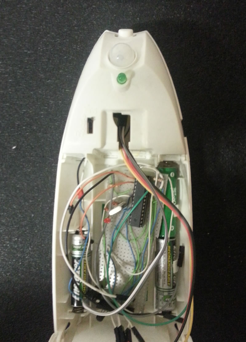
Voltage measured!!!
On Vera lite!!!
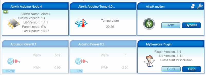
Battery Version!!!!!
-
External power supply to radio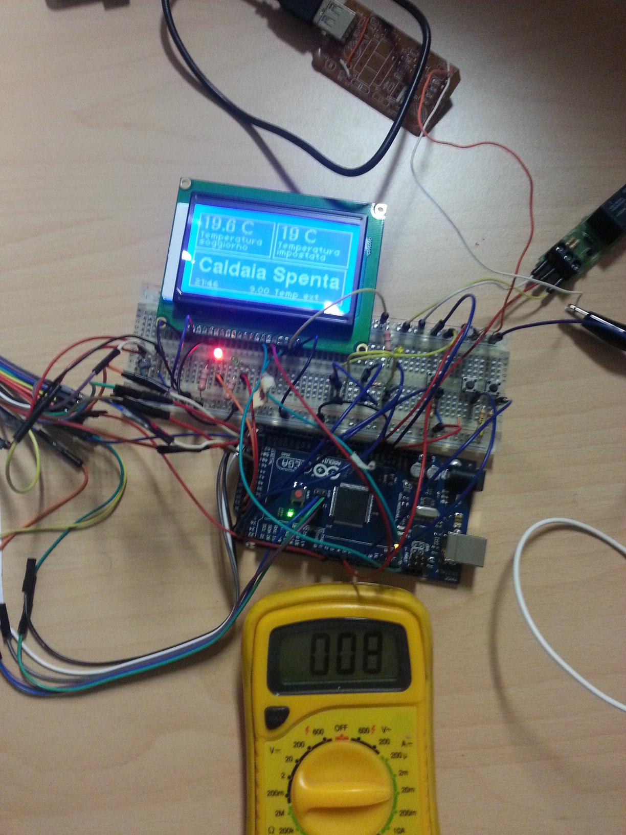
Relay on
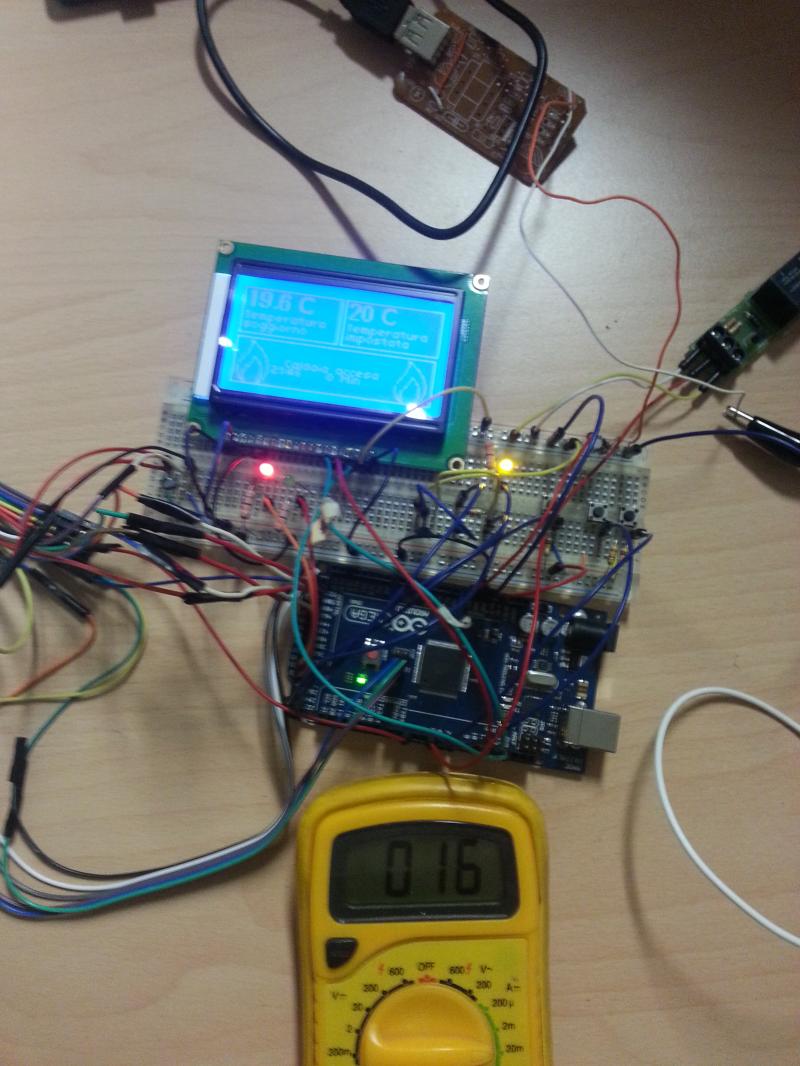
Only 3.3 volt
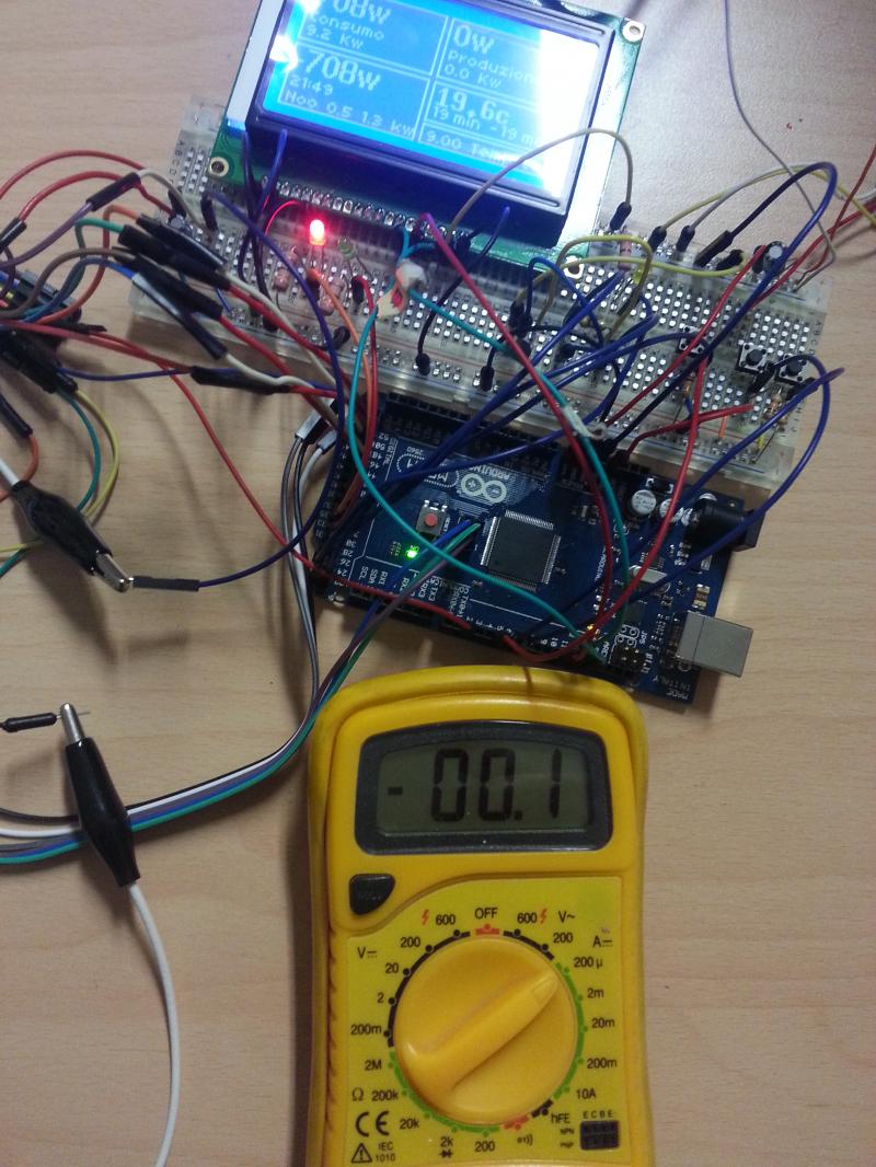
I do not know if I measured correctly, and my instrument is accurate !!!!!