Skip to content
  • MySensors
  • OpenHardware.io
  • Categories
  • Recent
  • Tags
  • Popular
Skins
  • Light
  • Brite
  • Cerulean
  • Cosmo
  • Flatly
  • Journal
  • Litera
  • Lumen
  • Lux
  • Materia
  • Minty
  • Morph
  • Pulse
  • Sandstone
  • Simplex
  • Sketchy
  • Spacelab
  • United
  • Yeti
  • Zephyr
  • Dark
  • Cyborg
  • Darkly
  • Quartz
  • Slate
  • Solar
  • Superhero
  • Vapor

  • Default (No Skin)
  • No Skin
Collapse
Brand Logo
G

Gunther

@Gunther
About
Posts
13
Topics
2
Shares
0
Groups
0
Followers
0
Following
0

Posts

Recent Best Controversial

  • Solar cell support with non-rechargeable batteries
    G Gunther

    As this thread turns into my personal highlights of silly mistakes: Another word of caution for anybody who wants raw battery values sent:
    sendBatteryLevel only uses 8-bit: i.e. value from 0-255. Don't try to send your raw 10-bit sensed input from e.g. A0 directly with it.

    bool sendBatteryLevel(const uint8_t level, const bool ack = false);
    

    Make sure you divide by 4 or use something like:

    int sensorValue = analogRead(ANALOGUE_SENSE_PIN) >> 2;
        sendBatteryLevel(sensorValue);
    
    My Project

  • Solar cell support with non-rechargeable batteries
    G Gunther

    @Nca78 Yes, that should have been clear to me by now.

    I just lost some time trying to burn the boot loader as always I got this error:

    avrdude: stk500_getparm(): (a) protocol error
    

    Checked, tested and even redid the soldering to exclude any wiring problems. Turns out adding a cap (0.1 µF in my case) between the programmers GND and RST did the trick.

    Thank you all!

    My Project

  • Solar cell support with non-rechargeable batteries
    G Gunther

    @gohan But how do I handle the different voltages? The Nano has 5V powered from USB, and I supplied the Mini Pro with 3.3V. But can't connecting the SPI pins lead to havoc? I read stuff in the ArduinoISP sketch like :

    MISO °. . 5V (!) Avoid this pin on Due, Zero...
    

    Should I just leave out the MISO connection?

    My Project

  • Solar cell support with non-rechargeable batteries
    G Gunther

    Ok BOD as in brownout detection. I'll follow you into the rabbit hole and try to burn a new bootloader. Trying to figure out if I can use my 5V Arduino Nano to burn the boot loader onto the 3.3V Mini Pro...

    My Project

  • Solar cell support with non-rechargeable batteries
    G Gunther

    @neverdie said in Solar cell support with non-rechargeable batteries:

    Did you remember to remove the LDO? Because otherwise it gets backfed, which is not what you want.

    I don't understand, the LDO is needed for charging the supercaps?

    @neverdie said in Solar cell support with non-rechargeable batteries:

    Also, yes, in theory you are running it out of Atmel's official spec if running at 8mhz at 1.8v, but I don't know and haven't read of even a single person who has ever had a problem with doing so. Doing this is very common.

    I would be very glad if I got to lower voltages, I am just trying to understand why I can't get below ~2.9V (at the Arduino).

    @Nca78 said in Solar cell support with non-rechargeable batteries:

    @gunther did you update fuses to lower BOD ?
    Still getting to grips with the terms. You mean the 1N4148 diodes? And BOD refers to lower voltage difference?

    No, not yet. I just plugged together parts, I could get my hands on to try to understand everything. I will then order the parts that are ideal.

    @NeverDie I promise to read all comments in existing threads!

    One thing that got me sidetracked is that I do not understand the analog read:
    I successfully confirmed that the Arduino Nano when attached to USB uses 2^10 channels with 1.1V reference.

    For the Arduino Mini Pro I also see 2^10 = 1024 channels with 1.1V reference when the power support comes from USB, what I assume to be a high quality power supply.
    However, when I run it off the capacitors + solar cells giving 3.3V I only get 2^8 = 256 channels with what appears to be ~1.1V reference. That is when I apply a voltage >1.1V I always get 255.
    I added various capacitors from 0.1-4.7 µF in parallel but that didn't change anything.
    How can that be?

    My Project

  • Solar cell support with non-rechargeable batteries
    G Gunther

    Thank you all for the information!

    @neverdie Ok, so now I have desoldered the Arduino Pro Mini power regulator and I now see a sleep current of 6µA with 3.2V.

    One thing I see is that the node only works down to 3V. With 2.5V it is not stable anymore. This is just the Arduino Pro Mini with attached NRF24L01. Maybe this is expected? I checked visually that I have indeed the 8MHz variant.
    alt text
    I just tried to test it with parts I could get my hands on.

    Could someone please tell me why the Battery Powering page advises to cut Vout? And what is it? It seems to me that this disconnects the Vcc on the shorter end? To what consumption does the connection lead. I find it convenient to have another Vcc pin available.

    My Project

  • Solar cell support with non-rechargeable batteries
    G Gunther

    @neverdie Will try! But that means the NRF24L01 is also out? And am I correct to connect the 2.7V to VCC not RAW?

    My Project

  • Solar cell support with non-rechargeable batteries
    G Gunther

    @neverdie How do you get from 2.7V to 3.3V? With another DC/DC booster?

    My Project

  • Solar cell support with non-rechargeable batteries
    G Gunther

    @johnrob Ok, just like with a resistor. Thank you for clearing this up. I assumed but wasn't sure.

    @gohan So only good weather updates? ;) From a practical standpoint solar cells are probably more of a hassle but the beauty of the concept...

    My Project

  • Solar cell support with non-rechargeable batteries
    G Gunther

    @gohan Thank you for clearing this up! Couldn't find anything on the consumption of these diodes.
    Using just 2 AA would indeed be the easiest, however I wanted to tinker around ;)

    My Project

  • Solar cell support with non-rechargeable batteries
    G Gunther

    Hi!

    So I am playing around with battery powered nodes and two very old solar cells that I have laying around. I am going to try to use supercaps but until they arrive, I would like a setup with non-rechargeable batteries. I am following the threads of @NeverDie and @gohan, from which I learned a lot.

    The solar cells spike up to 7V when in sun, on a cloudy day more like 4.5V, so in direct competition with the batteries. (I don't really have any specs.)

    0_1518796124078_Arduino-Solar-Nonrechargable.png

    In the attached image I added a 1N4148 diode to protect the non-rechargable batteries.
    -) Is this a good thing? Or will they consume to much power and result in a trade-off solar earnings vs. additional power consumption?

    (I know this setup is not as power saving as possible as it uses the Arduino's power regulator. However I destroyed desoldered the Arduino LED.)

    -) Do I need a need some kind of protection e.g. LEDs if the solar cells voltage should be too high?

    Concerning general battery conservation: The guide on how-to measure the battery level uses 1MΩ + 470kΩ attached to the power source.
    -) Wouldn't it save another few µA to to connect to a digital output which would only be set to OUTPUT 0V when measuring the battery level? No additional draining over the resistors.

    My Project

  • No communication with NRF24L01 on RPi3 64bit [SOLVED]
    G Gunther

    @gunther After fighting with this problem for some days, I now got it working. The solution was to use the BCM driver instead of SPIDEV.

    I achieved that by commenting out the 32 bit gcc flags in ./configure

    function gcc_cpu_flags {
        local soc=$1
        case $soc in
        BCM2835)
            flags="-march=armv6zk -mtune=arm1176jzf-s -mfpu=vfp -mfloat-abi=hard"
            ;;
        BCM2836)
            flags="-march=armv7-a -mtune=cortex-a7 -mfpu=neon-vfpv4 -mfloat-abi=hard"
            ;;
        BCM2837)
            flags=""
            #flags="-march=armv8-a+crc -mtune=cortex-a53 -mfpu=neon-fp-armv8 -mfloat-abi=hard"
            ;;
    

    and running configure with this options:

    $ ./configure --my-transport=nrf24 --my-gateway=ethernet --my-port=5003 --soc=BCM2837
    

    Hope this shortens the learning curve for 64bit Rasperry Pi users!

    Troubleshooting

  • No communication with NRF24L01 on RPi3 64bit [SOLVED]
    G Gunther

    Hi!

    Just recently discovered MySensors and this is what I was looking for!
    Unfortunately I can't get communications my RPI3 to communicate with a NRF24L01.

    My setup: RPi3 with a custom kernel 4.13.16 using 64bit, with loaded kernel module spi_bcm2835.

    $ uname -r
    4.13.16-v8+
    
    $ cat /boot/config.txt
    [...]
    dtparam=spi=on
    
    $ lsmod
    [...]
    spi_bcm2835            20480  0
    
    $ ls /dev/spidev0.*
    /dev/spidev0.0  /dev/spidev0.1
    

    I use the dev-branch (also tried stable, same behavior):

    $ ./configure --prefix=/data/home/gunther/mysensors --my-transport=nrf24 --my-gateway=ethernet --my-port=5003 
    [SECTION] Detecting target machine.
      [OK] machine detected: SoC=unknown, Type=unknown, CPU=aarch64.
    [SECTION] Checking GPIO Sysfs.
      [OK] /sys/class/gpio/export found
    [SECTION] Detecting SPI driver.
      [OK] SPI driver detected:SPIDEV.
    [SECTION] Detecting init system.
      [FAILED] unknown init system.
    [SECTION] Saving configuration.
    [SECTION] Cleaning previous builds.
    [OK] Finished.
    

    The unknown init system should be fine, as I do not want to create any startup scripts or move files somewhere.

    Running the gateway as root gives:

    $ ./bin/mysgw -d
    mysgw: Starting gateway...
    mysgw: Protocol version - 2.2.1-alpha
    mysgw: MCO:BGN:INIT GW,CP=RNNGL---,VER=2.2.1-alpha
    mysgw: TSF:LRT:OK
    mysgw: TSM:INIT
    mysgw: TSF:WUR:MS=0
    mysgw: !TSM:INIT:TSP FAIL
    mysgw: TSM:FAIL:CNT=1
    mysgw: TSM:FAIL:DIS
    mysgw: TSF:TDI:TSL
    

    This tells me that the communication between radio and RPI fails.

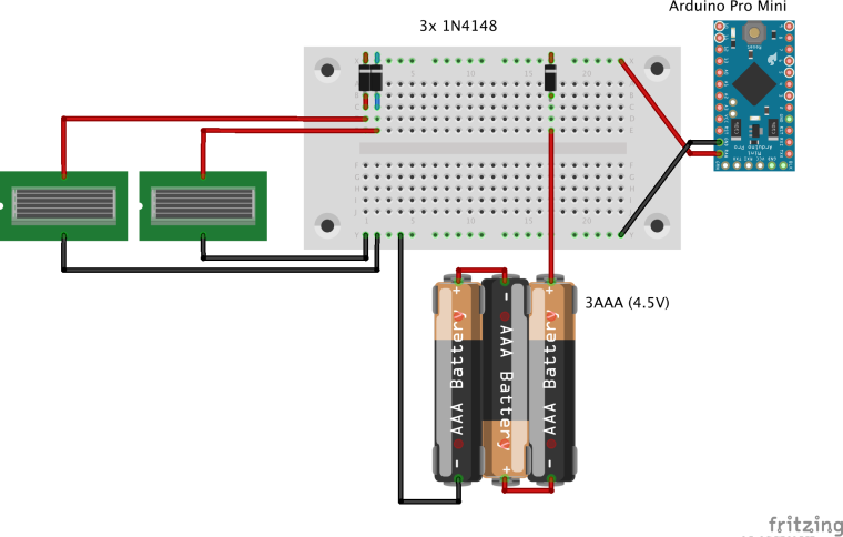
    I (more than) triple-checked the wiring.
    I use a voltage regulator from 5V to 3.3V and have a 47µF capacitor between GND and 3.3V. I also tried a different voltage regulator and NRF24L01.

    I assume the radio itself should be fine because attached to a Arduino Nano (with voltage regulator, without condensator) I see:

    16 MCO:BGN:INIT NODE,CP=RNNNA---,VER=2.2.0
    25 TSM:INIT
    26 TSF:WUR:MS=0
    33 TSM:INIT:TSP OK
    35 TSM:FPAR
    37 TSF:MSG:SEND,255-255-255-255,s=255,c=3,t=7,pt=0,l=0,sg=0,ft=0,st=OK:
    2046 !TSM:FPAR:NO REPLY
    

    Which I expect to the missing gateway.

    -) Is the SPIDEV driver ok? BCM does not compile for 64bit.
    -) Do I need to activate any GPIO ports with
    echo "$i" > /sys/class/gpio/export or anything alike?
    -) Is it ok, that I use other GPIO ports directly for other things?
    -) Is there a way to test that SPI is working properly?

    Thanks!

    Troubleshooting
  • Login

  • Don't have an account? Register

  • Login or register to search.
  • First post
    Last post
0
  • MySensors
  • OpenHardware.io
  • Categories
  • Recent
  • Tags
  • Popular