I have been using rf24 radios before mysensors, and back then everything didn't worked so good as with mysensors.
Awesome work, I think it's time for a donation at least for some 🍻 for holidays for developers. They deserve it.
I have been using rf24 radios before mysensors, and back then everything didn't worked so good as with mysensors.
Awesome work, I think it's time for a donation at least for some 🍻 for holidays for developers. They deserve it.
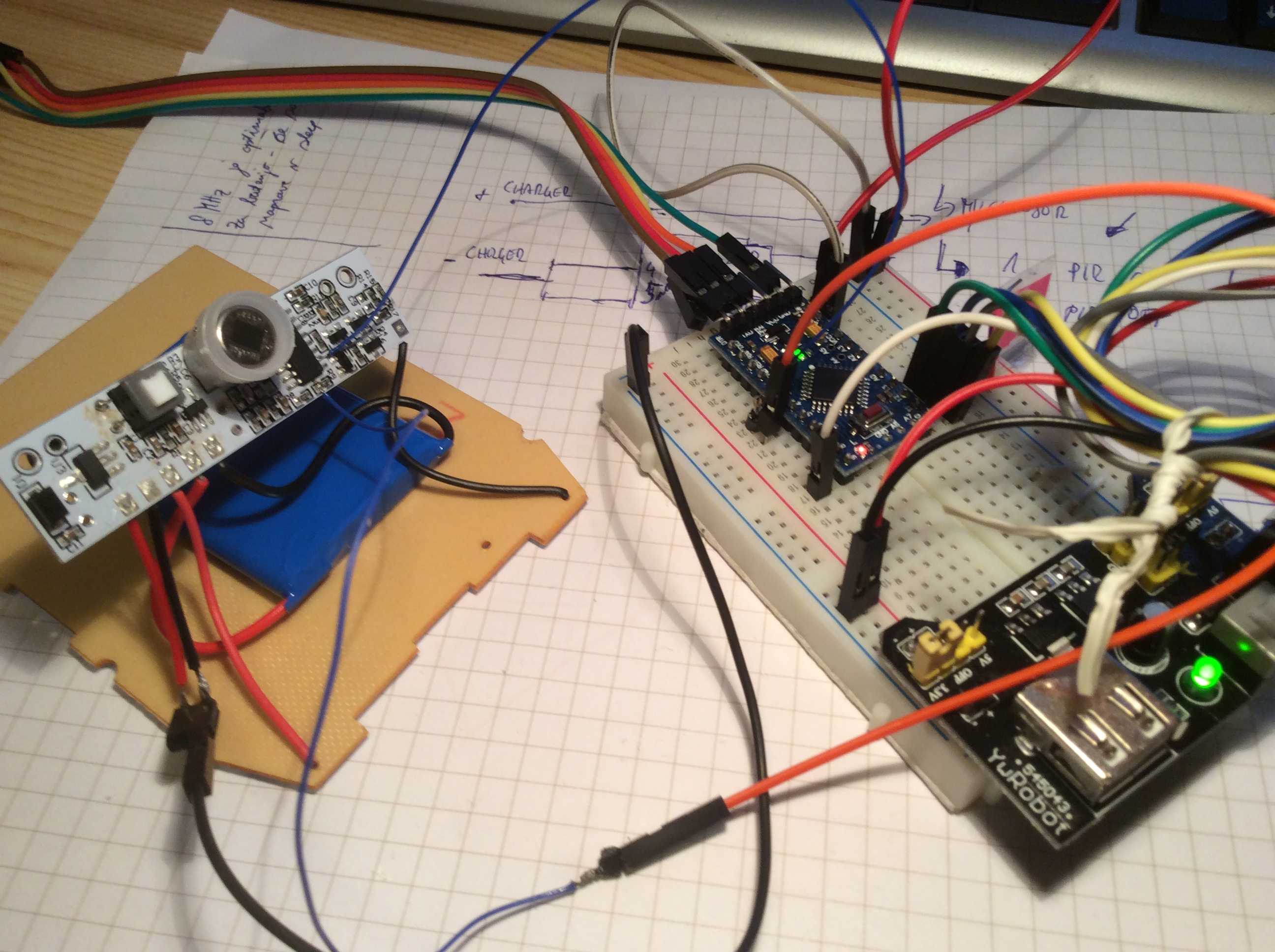
@GertSanders I think i managed to successfully connect arduino with solar lamp.
My prototype is working, and has the following functions:
I will post the code later, but every part works with default "mysensor" examples
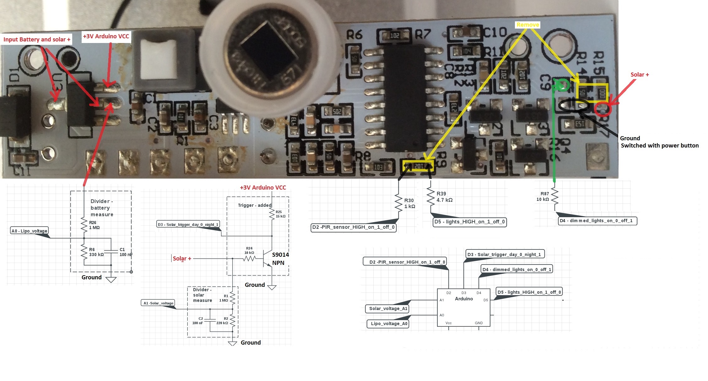
How to connect and how to add elements see picture:
@jemish if I understand right, as he says in description, it's intended for connecting 2 binary switch - for example:
For use in let's say in security system for a true detection that someone is present.
If in the future another sensor is connected, you can update the node software over air.
Please correct me if understand this wrong.
Otherwise @GeartSanders great job as alway. I have order your battery based (no SMD) node pcb and received them yesterday. Now the fun (soldering) begins:)
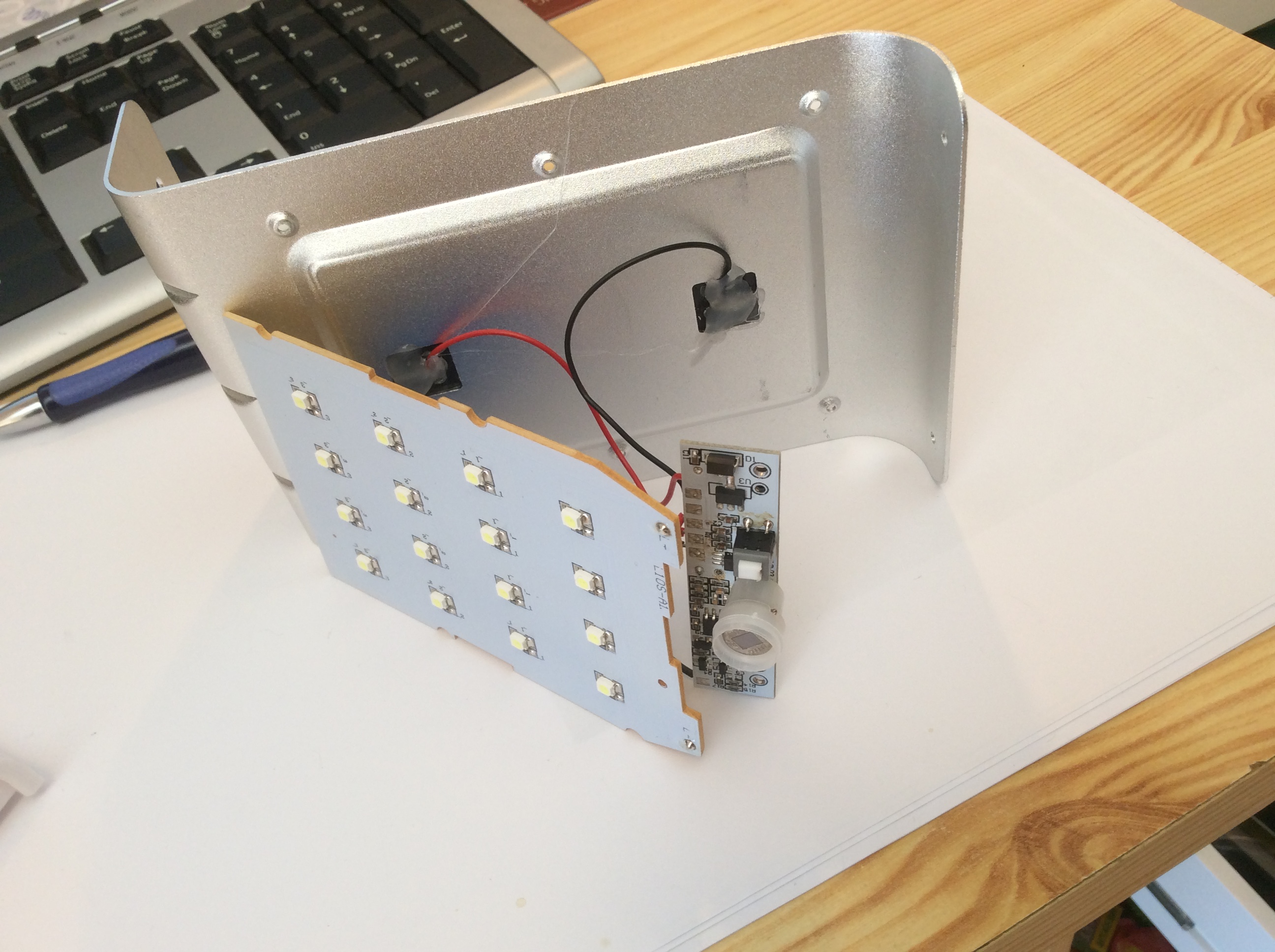
This would nicely fit into Chinese solar Lipo powered PIR led lamp.
http://www.aliexpress.com/item/New-Generation-16-LED-Solar-Power-Energy-PIR-Infrared-Motion-Sensor-Garden-Security-Lamp-Outdoor-Light/32336307599.html
We would only need 3,3 regulator to feed radio and arduino.
This way we could have smart mysensors aware security solar powered PIR sensor and LED garden lamp.
But it would be challenging to hack original circuit so it would be mysensors aware.
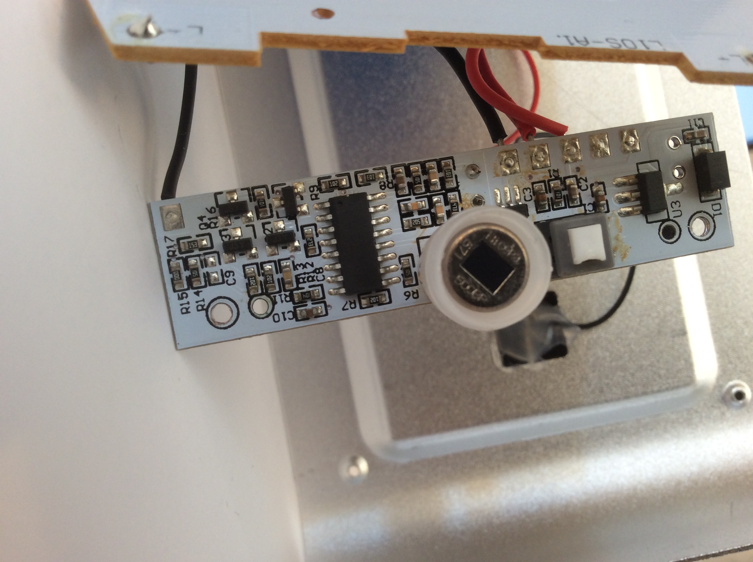
I'm willing to check elements and do additional circuit verification. But ic is without id. I think it is BISS0001?
What do you guys think? I can provide additional information if somebody is interested?
I think "mysensors" aware chinese LED solar lamp could work with a little effort, prototype is working now ( thanks to the forum members for help)
What needs to be done:
disconnect BISS0001 pin 2 from circuit (i have cut circuit wire on the back of PCB)
connect BISS0001 pin 2 to input pin 3 of arduino pro mini (3,3 V model)
connect resistor R9 (smd 102 - 1kohm) to output pin 4 of arduino which drives the transistor(Y1) base
i think that the easiest way would be to remove resister R9 from circuit. Then connect left part of resistor to input pin of arduino,
then wire to arduino output (pin 4) resistor 1K and then connect to right part of removed transistor.
Now i can use the solar light as motion detection and control LED lights independantly.
Received PUBLISH (d0, q0, r0, m0, 'mygateway1-out/11/12/1/0/16', ... (1 bytes))
0
Received PUBLISH (d0, q0, r0, m0, 'mygateway1-out/11/12/1/0/16', ... (1 bytes))
1
but i can control the lights
root@kali:~# mosquitto_pub -d -h 192.168.1.115 -t "mygateway1-in/11/1/1/0/2" -m "1"
Received CONNACK
Sending PUBLISH (d0, q0, r0, m1, 'mygateway1-in/11/1/1/0/2', ... (1 bytes))
root@kali:~# mosquitto_pub -d -h 192.168.1.115 -t "mygateway1-in/11/1/1/0/2" -m "0"
only when they are not charging (someone would need to figure out how to connect/disconnect
the solar charging - circuit now automatically disconnects the LEDs when there is voltage on solar cell and the battery is charging)
usage example:
with many solar lights on the garden if motion is detected on one we can light on all of them,
they can all blink as an alarm, (i would need help with code)
when we need light we can turn lights on from mobile app
or any other usage (control something that can be controlled with the power of lipo battery )
I think it would be good idea to meassure battery voltage, what divider should i use to meassure Lipo battery voltage, when arduino is powered from 3.0V battery (solar lamp onboard regulator is 3.0V), that we dont drain battery to much
i have combined motion detection and relay scetch:
the code is below (its not optimized, but it works):
// Enable debug prints
#define MY_DEBUG
#define MY_NODE_ID 11
// Enable and select radio type attached
#define MY_RADIO_NRF24
//#define MY_RADIO_RFM69

#include <SPI.h>
#include <MySensor.h>

unsigned long SLEEP_TIME = 120000; // Sleep time between reports (in milliseconds)
#define DIGITAL_INPUT_SENSOR 3   // The digital input you attached your motion sensor.  (Only 2 and 3 generates interrupt!)
#define INTERRUPT DIGITAL_INPUT_SENSOR-2 // Usually the interrupt = pin -2 (on uno/nano anyway)
#define CHILD_ID 12   // Id of the sensor child

boolean lastMotion = false;

// Initialize motion message
MyMessage msg(CHILD_ID, V_TRIPPED);

#define RELAY_1  4  // Arduino Digital I/O pin number for first relay (second on pin+1 etc)
#define NUMBER_OF_RELAYS 1 // Total number of attached relays
#define RELAY_ON 1  // GPIO value to write to turn on attached relay
#define RELAY_OFF 0 // GPIO value to write to turn off attached relay

void setup()
{
  pinMode(DIGITAL_INPUT_SENSOR, INPUT);      // sets the motion sensor digital pin as input

    for (int sensor=1, pin=RELAY_1; sensor<=NUMBER_OF_RELAYS;sensor++, pin++) {
    // Then set relay pins in output mode
    pinMode(pin, OUTPUT);
    // Set relay to last known state (using eeprom storage)
    digitalWrite(pin, loadState(sensor)?RELAY_ON:RELAY_OFF);
  }
}

void presentation()  {
  // Send the sketch version information to the gateway and Controller
  sendSketchInfo("Motion Sensor and pir", "1.0");

  // Register all sensors to gw (they will be created as child devices)
  present(CHILD_ID, S_MOTION);
    for (int sensor=1, pin=RELAY_1; sensor<=NUMBER_OF_RELAYS;sensor++, pin++) {
    // Register all sensors to gw (they will be created as child devices)
    present(sensor, S_LIGHT);
  }
}

void loop()
{
  // Read digital motion value
  boolean tripped = digitalRead(DIGITAL_INPUT_SENSOR) == HIGH;

 if (lastMotion != tripped) {
  Serial.println(tripped);
  lastMotion = tripped;
  send(msg.set(tripped?"1":"0"));  // Send tripped value to gw
 }
  // Sleep until interrupt comes in on motion sensor. Send update every two minute.
  //sleep(INTERRUPT,CHANGE, SLEEP_TIME);
}

void receive(const MyMessage &message) {
  // We only expect one type of message from controller. But we better check anyway.
  if (message.type==V_LIGHT) {
     // Change relay state
     digitalWrite(message.sensor-1+RELAY_1, message.getBool()?RELAY_ON:RELAY_OFF);
     // Store state in eeprom
     saveState(message.sensor, message.getBool());
     // Write some debug info
     Serial.print("Incoming change for sensor:");
     Serial.print(message.sensor);
     Serial.print(", New status: ");
     Serial.println(message.getBool());
   }
}
@GertSanders thanks, you have motivated my research
@Dylano the purpose of this project was exactly what you have asked.
The lamp is now mysensors aware.
Every task can be operated separately.
When there is dark, the trigger is send, when the sun shines, the trigger is send. (transistor as switch). In scetch i use it as magnet switch part of code. When trigger is received (can wake up arduino), than you decide with controller what you want to do .
PIR acts as classic PIR sensor and can also be used as trigger. (can wake up arduino), than you decide with controller what you want to do.
The Lamp have two phases and can be controlled with controller (i control it over mqtt for now)
phase one is dimmed light (relay 1)
phase two is high bright light (relay 2)
Below is code that works for now. I wil improve it in next few days
// Enable debug prints
#define MY_DEBUG
#define MY_NODE_ID 11
// Enable and select radio type attached
#define MY_RADIO_NRF24
//#define MY_RADIO_RFM69

#include <SPI.h>
#include <MySensor.h>
#include <Bounce2.h>

//unsigned long SLEEP_TIME = 120000; // Sleep time between reports (in milliseconds)
#define DIGITAL_INPUT_SENSOR 2   // The digital input you attached your motion sensor.  (Only 2 and 3 generates interrupt!)
//#define INTERRUPT DIGITAL_INPUT_SENSOR-2 // Usually the interrupt = pin -2 (on uno/nano anyway)
#define CHILD_ID 12   // Id of the sensor child

boolean lastMotion = false;

// Initialize motion message - start
MyMessage msg(CHILD_ID, V_TRIPPED);

//trigger solar power day on/off -start
#define CHILD_ID_SW 5
#define BUTTON_PIN  5  // Arduino Digital I/O pin for button/reed switch
Bounce debouncer = Bounce();
int oldValue = -1;

// Change to V_LIGHT if you use S_LIGHT in presentation below
MyMessage SolarMsg(CHILD_ID_SW, V_TRIPPED);
// trigger solar - end

#define RELAY_1  3  // Arduino Digital I/O pin number for first relay (second on pin+1 etc)
#define NUMBER_OF_RELAYS 2 // Total number of attached relays
#define RELAY_ON 1  // GPIO value to write to turn on attached relay
#define RELAY_OFF 0 // GPIO value to write to turn off attached relay

void setup()
{
	//trigger solar power day on/off - start
	// Setup the button
	pinMode(BUTTON_PIN, INPUT);
	// Activate internal pull-up
	digitalWrite(BUTTON_PIN, HIGH);

	// After setting up the button, setup debouncer
	debouncer.attach(BUTTON_PIN);
	debouncer.interval(5);
	//trigger solar - end


	pinMode(DIGITAL_INPUT_SENSOR, INPUT);      // sets the motion sensor digital pin as input

	for (int sensor = 1, pin = RELAY_1; sensor <= NUMBER_OF_RELAYS; sensor++, pin++) {
		// Then set relay pins in output mode
		pinMode(pin, OUTPUT);
		// Set relay to last known state (using eeprom storage)
		digitalWrite(pin, loadState(sensor) ? RELAY_ON : RELAY_OFF);
	}
}

void presentation() {
	// Send the sketch version information to the gateway and Controller
	sendSketchInfo("Motion Sensor and light", "1.0");

	// Register all sensors to gw (they will be created as child devices)
	present(CHILD_ID, S_MOTION);
	for (int sensor = 1, pin = RELAY_1; sensor <= NUMBER_OF_RELAYS; sensor++, pin++) {
		// Register all sensors to gw (they will be created as child devices)
		present(sensor, S_LIGHT);

		// Register binary input sensor to gw (they will be created as child devices)
		// You can use S_DOOR, S_MOTION or S_LIGHT here depending on your usage.
		// If S_LIGHT is used, remember to update variable type you send in. See "msg" above.
		present(CHILD_ID_SW, S_DOOR);
	}
}

void loop()
{
	// Read digital motion value
	boolean tripped = digitalRead(DIGITAL_INPUT_SENSOR) == HIGH;

	if (lastMotion != tripped) {
		Serial.println(tripped);
		lastMotion = tripped;
		send(msg.set(tripped ? "1" : "0"));  // Send tripped value to gw
	}
	// Sleep until interrupt comes in on motion sensor. Send update every two minute.
	//sleep(INTERRUPT,CHANGE, SLEEP_TIME);

	//trigger solar power day on/off - start
	debouncer.update();
	// Get the update value
	int value = debouncer.read();

	if (value != oldValue) {
		// Send in the new value
		send(SolarMsg.set(value == HIGH ? 1 : 0));
		oldValue = value;
	//trigger solar power day on/off - stop
	}
}

void receive(const MyMessage &message) {
	// We only expect one type of message from controller. But we better check anyway.
	if (message.type == V_LIGHT) {
		// Change relay state
		digitalWrite(message.sensor - 1 + RELAY_1, message.getBool() ? RELAY_ON : RELAY_OFF);
		// Store state in eeprom
		saveState(message.sensor, message.getBool());
		// Write some debug info
		Serial.print("Incoming change for sensor:");
		Serial.print(message.sensor);
		Serial.print(", New status: ");
		Serial.println(message.getBool());
	}
}```