@Eric-Buhring great to hear that you managed to get it working. I have used solution like this (arduino+eth. shield+rf24) for some time.
Now I have switched to esp8266+rf24(version with antenna) as a gateway, it is a cool (and smaller) solution
gyro
@gyro
Posts
-
Can't get message from OpenHab to MySensor -
Can't get message from OpenHab to MySensor@Eric-Buhring what do you use for gateway?
Is it arduino + Ethernet + rf24?
Try with mqttclient scetch for gw.
Than setup mqtt server on your network (install mosquitto on controller). -
💬 Various bootloader files based on Optiboot 6.2@GertSanders thanks for this bootloader pack. After one day of trying I was still unable to upload scetches to atmega burned with bootloader 8Mhz image to atmeg328 - 28 pin DIL from this: https://forum.mysensors.org/topic/3018/tutorial-how-to-burn-1mhz-8mhz-bootloader-using-arduino-ide-1-6-5-r5/1 tutorial.
With your 0_1463253058014_atmega328p.zip pack unzipped to "hardware" directory worked like a charm. -
Happy Bubbles Bluetooth Presence DetectorHello, @nemik
Congratulations on a very nice project.
Do you think it would be possible to use nrf24l01+ modul in your solution?
Because this is mysensors main radio. And it is possible to fake with it Bluetooth beacons as stated here:
http://dmitry.gr/index.php?r=05.Projects&proj=11. Bluetooth LE fakery
And here:
http://spaghettiwires.com/posts/temperature-beacon/Thanks for your contribution to the open-source community. Hope that radio rf24 will fit in your solution, that way additional functionality can be added to mysensors - that is sensors locations.
-
MySensors 2.0.0 ReleasedI have been using rf24 radios before mysensors, and back then everything didn't worked so good as with mysensors.
Awesome work, I think it's time for a donation at least for some 🍻 for holidays for developers. They deserve it.
-
Can't upload MQTT Client Gateway to ESP8266 -
Chinese Solar Lipo powered PIR led lamp.@ranseyer
This one looks is a little complicated. I think you should wait for china version :)
Take a picture of other side of circuit also. -
Chinese Solar Lipo powered PIR led lamp.@korttoma great that you maneged to connect it lamp..
I don't know if analog reference is than set for all analog interfaces..
Just one more thing you should adjust:
I have figured out that I need to raise alarm for lower threshold for battery to higher than 3V (now is 2.5V!) because regulator voltage drop is ~250mV, and mini pro drops out at around 2.8V..
But the whole concept now works fairly good -
Chinese Solar Lipo powered PIR led lamp.Hi @korttoma
- yes battery sense is A0
- yes R1 and R2 are resistors values to measure Lipo voltage
-
Chinese Solar Lipo powered PIR led lamp.@korttoma
I did try some battery measurement variants. The following code works best for me. I suggest that you first try the following sketch.- measure the voltage with voltmeter on VCC pin and correct #define VREF value so it will be a close as possible to measured value before you integrate into case specific code
// define values for the battery measurement #define R1 1e6 #define R2 330e3 #define VMIN 2.8 #define VMAX 4.2 #define ADC_PRECISION 1023 #define VREF 1.13 int oldBatteryPcnt = 0; int batteryVoltage = 0; int BATTERY_SENSE_PIN = 0; int val = 0; void setup() { // use the 1.1 V internal reference #if defined(__AVR_ATmega2560__) analogReference(INTERNAL1V1); #else analogReference(INTERNAL); #endif Serial.begin(9600); } void loop() { //float batteryPcnt = getBatteryPercentage(); //val = analogRead(BATTERY_SENSE_PIN); //Serial.println(batteryVoltage); float batteryVoltage = getBatteryPercentage(); Serial.println(batteryVoltage); float batteryV= batteryVoltage; float batteryVmap = fabs(fmap(batteryV, 2.5, 4.2, 0.0, 1000.0)); int batteryPcnt = batteryVmap / 10; if (batteryPcnt >= 100) { batteryPcnt = 99; } Serial.print("Battery voltage: "); Serial.print(batteryPcnt); Serial.println(" %"); delay(2000); /*if (oldBatteryPcnt != batteryPcnt) { // Power up radio after sleep //gw.sendBatteryLevel(batteryPcnt); oldBatteryPcnt = batteryPcnt; }*/ // totally random test values } float getBatteryPercentage() { // read analog pin value int inputValue = analogRead(BATTERY_SENSE_PIN); // calculate the max possible value and therefore the range and steps float voltageDividerFactor = (R1 + R2) / R2; float maxValue = voltageDividerFactor * VREF; float voltsPerBit = maxValue / ADC_PRECISION; float batteryVoltage = voltsPerBit * inputValue; float batteryPercentage = ((batteryVoltage-VMIN)/(VMAX-VMIN))*100; //int batteryPercentage = map(batteryVoltage, 0, maxValue, 0, 100); //return batteryPercentage; return batteryVoltage; } float fmap(float x, float in_min, float in_max, float out_min, float out_max) { return (x - in_min) * (out_max - out_min) / (in_max - in_min) + out_min; } -
Chinese Solar Lipo powered PIR led lamp.@korttoma
Don't be sorry.I am not an circuits expert, I just try help you figure things out.
You wil have to test this lamp a little bit.
it looks that Q1 drives U1 active/not active when there is sun, but how/what turns on dimm lights in dark?Did you measure U1 pin 6 when pir active/not active?
-
Chinese Solar Lipo powered PIR led lamp.@korttoma
Are you sure that this light has two modes of operation or only one: when a person is present is activated for 15s and then switched off -
Chinese Solar Lipo powered PIR led lamp.@korttoma
sorry my typo: you are correct- U4 - HT33 is voltage regulator
- yes Q1 and Q2 are transistors
- U1 - PIR out test - measure voltage between PIN 6 and R3 when PIR is OF and ON. I think this drives Q2 (high brightness / low brightnes)
also take picture of other side of circuit board, beause i think Q1 is conected to R10 and
then further on the other side -
Chinese Solar Lipo powered PIR led lamp.@korttoma
Nice to see some interest in smart solar lamps :)
It looks like an updated version (at least i like it more from your pictures). Could you post an order link.
I think this one should be even easier to intercept with "mysensors", beacause i see only two transistors and circuit connectios are clearly visible.so lets try to understand the circuit:
-U3 is probably battery protection circuit- Q1 i think is voltage regulator HT33 - to power arduino wih 3.3V (meassure voltage)
- take a photo of PIR sensor from front side (is there any ic elements)?
- U1 - i would guess PIR sensor IC logic - leg 6 (count from dot on IC) should be output (meassure voltage - high 3,3 V when motion detected):
-if it is output from PIR just remove R3 and IC ouput goes over resistor to you arduino input. - the output goes over resistor to Q2
-whats is left - you have to figure out what drives resistor Q1(J3y) : - i gues its driven by solar cell, than collector is connected to resistor R10, resesitor is than connected over board to the other side.......
-
Chinese Solar Lipo powered PIR led lamp.@Dylano Great to hear that the light has the same board...please post a picture.
My light is still protoype connected together on protoboard - connected to arduino pro mini - i can post only a picture connected elements on protoboard for now.
I am trying to put all together in openhab now.
I will try to make a list of exact elements.
I have free D2 pin on arduino pro mini. -
Chinese Solar Lipo powered PIR led lamp.@siklosi Resistor is used as transisistor base resistor. This was the best way to connect i could think off. But you need two output pins - 2 transistors are controlled.
first PIN - lights ON/OFF
second PIN - ligths bright ON/OFF -
Chinese Solar Lipo powered PIR led lamp.@GertSanders thanks, you have motivated my research
@Dylano the purpose of this project was exactly what you have asked.
The lamp is now mysensors aware.
Every task can be operated separately.-
When there is dark, the trigger is send, when the sun shines, the trigger is send. (transistor as switch). In scetch i use it as magnet switch part of code. When trigger is received (can wake up arduino), than you decide with controller what you want to do .
-
PIR acts as classic PIR sensor and can also be used as trigger. (can wake up arduino), than you decide with controller what you want to do.
-
The Lamp have two phases and can be controlled with controller (i control it over mqtt for now)
-
phase one is dimmed light (relay 1)
-
phase two is high bright light (relay 2)
Below is code that works for now. I wil improve it in next few days
// Enable debug prints #define MY_DEBUG #define MY_NODE_ID 11 // Enable and select radio type attached #define MY_RADIO_NRF24 //#define MY_RADIO_RFM69 #include <SPI.h> #include <MySensor.h> #include <Bounce2.h> //unsigned long SLEEP_TIME = 120000; // Sleep time between reports (in milliseconds) #define DIGITAL_INPUT_SENSOR 2 // The digital input you attached your motion sensor. (Only 2 and 3 generates interrupt!) //#define INTERRUPT DIGITAL_INPUT_SENSOR-2 // Usually the interrupt = pin -2 (on uno/nano anyway) #define CHILD_ID 12 // Id of the sensor child boolean lastMotion = false; // Initialize motion message - start MyMessage msg(CHILD_ID, V_TRIPPED); //trigger solar power day on/off -start #define CHILD_ID_SW 5 #define BUTTON_PIN 5 // Arduino Digital I/O pin for button/reed switch Bounce debouncer = Bounce(); int oldValue = -1; // Change to V_LIGHT if you use S_LIGHT in presentation below MyMessage SolarMsg(CHILD_ID_SW, V_TRIPPED); // trigger solar - end #define RELAY_1 3 // Arduino Digital I/O pin number for first relay (second on pin+1 etc) #define NUMBER_OF_RELAYS 2 // Total number of attached relays #define RELAY_ON 1 // GPIO value to write to turn on attached relay #define RELAY_OFF 0 // GPIO value to write to turn off attached relay void setup() { //trigger solar power day on/off - start // Setup the button pinMode(BUTTON_PIN, INPUT); // Activate internal pull-up digitalWrite(BUTTON_PIN, HIGH); // After setting up the button, setup debouncer debouncer.attach(BUTTON_PIN); debouncer.interval(5); //trigger solar - end pinMode(DIGITAL_INPUT_SENSOR, INPUT); // sets the motion sensor digital pin as input for (int sensor = 1, pin = RELAY_1; sensor <= NUMBER_OF_RELAYS; sensor++, pin++) { // Then set relay pins in output mode pinMode(pin, OUTPUT); // Set relay to last known state (using eeprom storage) digitalWrite(pin, loadState(sensor) ? RELAY_ON : RELAY_OFF); } } void presentation() { // Send the sketch version information to the gateway and Controller sendSketchInfo("Motion Sensor and light", "1.0"); // Register all sensors to gw (they will be created as child devices) present(CHILD_ID, S_MOTION); for (int sensor = 1, pin = RELAY_1; sensor <= NUMBER_OF_RELAYS; sensor++, pin++) { // Register all sensors to gw (they will be created as child devices) present(sensor, S_LIGHT); // Register binary input sensor to gw (they will be created as child devices) // You can use S_DOOR, S_MOTION or S_LIGHT here depending on your usage. // If S_LIGHT is used, remember to update variable type you send in. See "msg" above. present(CHILD_ID_SW, S_DOOR); } } void loop() { // Read digital motion value boolean tripped = digitalRead(DIGITAL_INPUT_SENSOR) == HIGH; if (lastMotion != tripped) { Serial.println(tripped); lastMotion = tripped; send(msg.set(tripped ? "1" : "0")); // Send tripped value to gw } // Sleep until interrupt comes in on motion sensor. Send update every two minute. //sleep(INTERRUPT,CHANGE, SLEEP_TIME); //trigger solar power day on/off - start debouncer.update(); // Get the update value int value = debouncer.read(); if (value != oldValue) { // Send in the new value send(SolarMsg.set(value == HIGH ? 1 : 0)); oldValue = value; //trigger solar power day on/off - stop } } void receive(const MyMessage &message) { // We only expect one type of message from controller. But we better check anyway. if (message.type == V_LIGHT) { // Change relay state digitalWrite(message.sensor - 1 + RELAY_1, message.getBool() ? RELAY_ON : RELAY_OFF); // Store state in eeprom saveState(message.sensor, message.getBool()); // Write some debug info Serial.print("Incoming change for sensor:"); Serial.print(message.sensor); Serial.print(", New status: "); Serial.println(message.getBool()); } }``` -
-
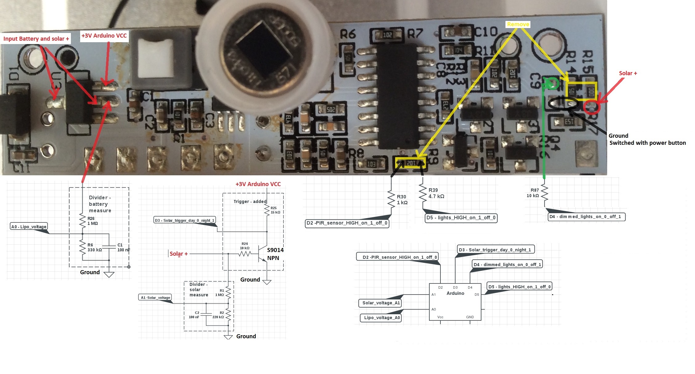
Chinese Solar Lipo powered PIR led lamp.@GertSanders I think i managed to successfully connect arduino with solar lamp.
My prototype is working, and has the following functions:
- Measure battery voltage (when charging it is alway 100% - makes sense)
- Measure solar voltage (can be omitted - but resistor should be there for a transistor to work properly)
- Solar power day/night trigger with transistor as a switch (can be used wake up arduino from sleep)
- PIR sensor (can be used wake up arduino from sleep)
- Lights on/off dimmed brightness
- Lights on/off high brightness ( original resistor R9 -1k was replaced with 4.7k - i think it draws to much current and sometimes hangs arduino)
I will post the code later, but every part works with default "mysensor" examples
How to connect and how to add elements see picture:
-
Chinese Solar Lipo powered PIR led lamp.@soif , @GertSanders
some progress was made, but i need an hardware advice.This is the part of schematic that drives the LEDs.
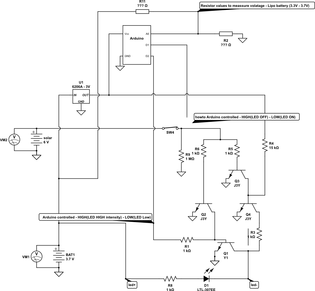
First the battery is not connected directly (as here in schematic) but over protection IC logic.
Question 1:
Current circuit works as follows:
- When solar cell voltage is higher than 0.7V , LED is OFF (sort off day/night sensor).
- When solar voltage is lower than 0,7V, LED is shining with low intensity
What is the the correct way to connect arduino pin D1 to take control over above described default behavior? (disconnect the line at SW4 and remove R9 -1Mohm)?
Question 2:
Which voltage measurement technique (internal reference or reference to regulated Vcc voltage) should i use to meassure Lipo voltage?
What are correct/recommended resistor value for optimal battery utilization.
Should this reference be used: https://github.com/rlogiacco/BatterySenseWould make sense to measure also solar cell voltage?
Question 3:
Is arduino pin D2 connect properly? It control two level LED intensity:
pin HIGH - LED glows with HIGH intensity (between led+ and led- is ~4V) pin LOW LED glows with LOW intensity (between led+ and led- is ~2,5V)Thanks for help and recommendations
I have asked the same here, but no perfect answer jet:
http://electronics.stackexchange.com/questions/218114/solar-battery-powered-leds-circuit-arduino-controlled