@nightbodom Arduino have a tutorial for this https://www.arduino.cc/en/Tutorial/ArduinoISP
hugch
Posts
-
💬 In Wall AC/DC Pcb (with Relay) for MySensors (SMD) -
💬 Dollhouse wireless nodeHi, great project. Do you have any experience with the battery lifetime in combination with different sensors?
-
Bridge between RF24 and RS485@ArduiSens No i mean not a ethernet gateway. I mean a gateway between RS485 and the wireless network.
Currently there exists only a gateway from RS485 to UART but not to the wireless network. -
Bridge between RF24 and RS485A repeater feature would be amasing. I posted a feature request on github, but i think it is better here:
I would like to build a wired network with RS-485 based sensors, because wireless signals can't go through the location where the sensors are. But outside of the metal house i can send and receive messages via NRF24L01.
So but the current MySensor library supports only a LAN, WLAN or serial gateway, but i need a NRF gateway. ;-)
Because there is no LAN or WLAN available. Would it possible to do this?
I think two ways could be useful:- a real gateway function
- only pass through between RS-485 and NRF without an extra gateway
Which one would be easier to implement? I could help with this, but i don't exactly know the best point to start at. Allows the current library structure this modification?
-
[solved] Need help for signing messages between nodes@Anticimex It was not a whitlesiting problem. But i think there was a wrong serial in the EEPROM. So i use the serial from the ATSHA device now.
It is new for me, that the signer information are stored in the EEPROM. I will try it with the presentation function again. -
💬 In Wall AC/DC Pcb (with Relay) for MySensors (SMD)Very nice project. And it is so nice that you thought about the fuses for the power supply and the relais. :-)
I have two additional ideas:- adding the ATSHA204 fo secure signing
- I could be to big to integrate but something like this (https://www.aliexpress.com/item/1Bit-AC-220V-Optocoupler-Isolation-Module-Testing-Board-Adaptive-for-PLC/32754734564.html) would be great to detect the in wall switch state.
-
[solved] Need help for signing messages between nodesThanks for your help @Anticimex. But nowit works. The solution was to clear the eeprom on both nodes.
@Anticimex said in Need help for signing messages between nodes:
Are you using whitelisting?
Yes i'm using whitlisting.
@Anticimex said in Need help for signing messages between nodes:
You also need to inform other nodes about your nodes signing preferences if you want to transmit node-to-node signed messages. This is done using signerPresentation(). It is automatically done for node-to-gateway, but you have to do it youself for node-to-node. It is NOT recommended to manipulate the signing tables directly using the SET_ macros.
Yes I know that it is not cemommended to use the macros but in my case it is the only solution.
Because my battery powerd node is sleeping in deep sleep mode and can only wake up on an external interrupt.
The interrupt from the NRF24l01 is disabled, otherwise the node wakes up every second (mybe a bug in version 2.1.1 ?).
So if the other node try to inform the battery node for signing messages, the information will not reached the battery node.
The current MySensors implementation withsignerPresentationworks only if the actuator node is on bevor the battery node. But this is not always the case.All nodes in my system have fixed ids. So it is no problem to tell my battery node that the actuator node needs signed messages. So it would be nice if we add a mysensors function to do that and not using the SET macros.
-
[solved] Need help for signing messages between nodesSo i tried something and i found a useful macro:
SET_SIGN(20);So with this macro i tell the mysensors signing library that the node 20 need signed messages.But Node
20says:Signature bad: [signature] 1245835 Signature verification failed! 1245852 !TSF:MSG:SIGN VERIFY FAILWith
MY_DEBUG_VERBOSE_SIGNINGi saw that theCurrent nonceandHMACoutput on both nodes are the same. But the signatur in message is not the same.
So what is going wrong?Both nodes are able to receive signed messages from the same master. The master and both nodes have the same HMAC key.
-
[solved] Need help for signing messages between nodesI have two nodes:
Node 20: an relays switch
Node 19: Motion detectorBoth nodes could communicated with signing with the gateway. Bit if i want so send a message from node 19 to node 20 it doesn't work.
So i found thesignerPresentationfunction. I tried to call it in node 20 and 19 but it didn't worked.At which device do I have to call the function?
I thought about device 19 in thepresentationfunction with theMyMessagefrom the Motion sensor and node 20 as destination to inform the library that the destination node needs signing. But the destination node says:551439 Message is not signed, but it should have been!Could anyone help me?
-
💬 Homini AC Powered Relay (2) Module@Samuel235 said in 💬 Homini AC Powered Relay (2) Module:
OMRON G3MB-202P
Okay I'm trying to help you with the fuse component. ;-)
I found a datasheet for the OMRON G3MB-202P. And there are enoght information to be known for fuse selection. :-)
I try to calculate it here (and i will try it with my bad English ;-) ).The most important information is the melting integral.
The Melting integral has A²s as unit. So this means the maximum current for a time can exists without damaging the device. For further information look at wikipedia.So we need any further information about:
- the protection which is present before (the typical circuit protection in private houses)
- the melting integral from the device which we want to protect
- the maximum voltage
- the maximum switching current
- the breaking capacity
- Inrush current for the switched devices (we can't know)
Typical values for an automatic circuit breaker in private houses are:
- from 25 to 100 A²s
- 230 V AC
- 16 A
So this protection isn't good enough for our relay. The relay have these values:
- 230 V AC
- 2 A maximum switching current
- I²t value (melting integral): 4 A²s
- the allowed inrush current over a small time is higher than the melting integral. It is a bit confusing i think, but if we calculate the protection for the given melting integral and it's fine. So we can define the parameters for the client (switching site of this application here)
The fuse have to be:
- I²s value higher or equal than the I²s value from the existing protection
- rating voltage over 230 V AC
- rating current 2 A or lower (because 2 A is the maximum at 25 °C, for 40 °C it is about 1.6 A)
- a maximum switching time of 1 second at 2 A or lower time with higher current but below 4A²s! To calculate use the switching time from the fuse datasheet an multiply it two times with the given current for this switching time.
And i think a fast blow fuse would be the best. There are SMD fuses with 10.1 x 3 mm and 250 V AC available.
If there is no fuse available with the values above, we could combine multiple fuses. A possible solution could be one bigger fuse for both relays and the ac/dc component. And a smaller fuse for the switching site of the relay and the HLK-PM01. But for this it is important that the circuit have only one input for the hot one (L) of 230 V and one output for each relay. In this case we could reduce the big connectors from 6 to 4. Like (L, N, Relay1, Relay2).
And the temperature fuse can work for all components too ;-)So the protection for the primary site of the HLK-PM01 is a problem i think. Because the are no information available about the I²s value from HLK-PM01.
I hope you can understand my English and could follow my explanation?
-
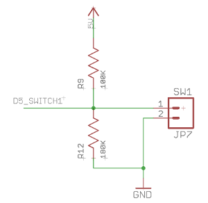
💬 Homini AC Powered Relay (2) ModuleBut if you use 5 V for the switch, you have to use a voltage divider or so to protect the atmega328p input, because the controller works with 3,3 V.
That is best practice however, because we are detecting high or low and not the actual voltage then we are okay here. From > what i have done in the past and also read again recently. I can't remember where i found that read otherwise i would link.
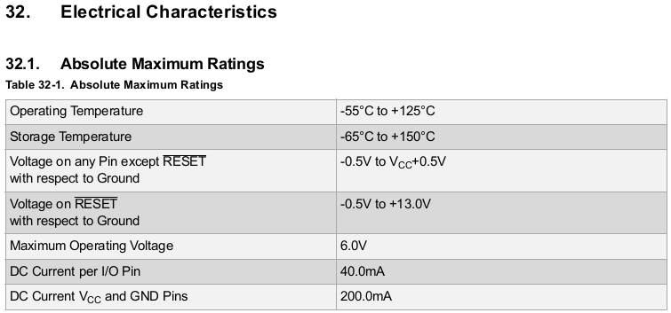
Sorry that is not correct. Pleas take a look at the atmega328p datasheet on page 365:

The maxim voltage on any pin (except RESET) by 3.3 V as Vcc is 3.8 V and not 5 V.
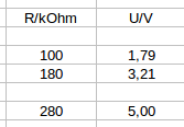
You can use an easy voltage divider like:


And for the fuses:
I know it is not easy. I worked for a view month by a fuse manufacturer as student. The problem here is the missing information from the relay manufacturer right? -
💬 Homini AC Powered Relay (2) Module@Samuel235 said in 💬 Homini AC Powered Relay (2) Module:
@hugch - Thanks for the interest in this product, its nice to see someone interested in something i've made.
Why your are using 5 V for the external switchs?
The 5V for the switches was simply because i needed to use 5V for the relays it made the 5V line easier to route to the switch terminals. I could just route 3V3 but it was more convenient at the time to use the 5V line.
But if you use 5 V for the switch, you have to use a voltage divider or so to protect the atmega328p input, because the controller works with 3,3 V.
And why your are using the ac/dc module with 5 V and not 3,3 V (HLK-PM03) directly? With this you can remove the voltage regulator.
I needed to get a stable 5V to switch the relays, in prototyping i couldn't get the relays to be stable on 3V.
Okay, sorry I thought there are such relays with 3V available.
Than forget it and use the 5 V one ;-)Which smd fuses do you use? I think there is no 230 V AC fuse with SMD 1206 package available, is it?
You're right, there isn't any advertised anywhere to be 240V rated. I also found that there are alot of SMD fuses that do not have a voltage rating and so i took a risk knowing that i could remove this feature easily by just bridging the gap with solder. Even though i have ran this module without the fuse blowing at 240v, i'm pretty sure this is not a stable method of running this module. In Rev1.2 i have removed this feature. I'm looking at possibly putting in glass fuses on holders that you can remove via a panel in the 3D printed enclosure. Not too confident about it right now though. The routing on the board would have to be messed with, rather a lot.
Okay. I will wait for the next revision. But I hope it will be possible to add any type of fuse for 230 V for the relay. Because protection is important for this type of relais. In Germany the most common protection for private houses is 16 A and the relay could not switch 16 A.
I am very excited about the next version. You did a great job.
-
💬 Homini AC Powered Relay (2) ModuleHi,
I think this is the best and nice one of all the similar projects for 2 relay switching here ;-)Just three things I don't understand too. ;-)
- Why your are using 5 V for the external switchs?
- And why your are using the ac/dc module with 5 V and not 3,3 V (HLK-PM03) directly? With this you can remove the voltage regulator.
- Which smd fuses do you use? I think there is no 230 V AC fuse with SMD 1206 package available, is it?
And @tonnerre33:
The HLK-PM03 have output short circuit protection in it: http://www.hlktech.net/product_detail.php?ProId=59 -
Smart Light Switch 220vHi,
nice projet. I am very interested in it.
But why you are using 5 V and not 3.3 V? The ATmea328 works with 3.3 V too and the NRF have to use 3.3 V.
The only restriction on 3.3 V is the clock limitation for the Atmega (8 MHz). But with no crystal it don't care.
For example you could use an HLK-PM03 instead of HLK-PM01 and remove the linear voltage regulator. So you get more space an everything have the same voltage level.And another point is, it is recommended to use a capacitor (0.1 µF) to ground for each voltage pin (Vcc, Avcc, Aref).
-
💬 AC-DC double solid state relay module@Nca78 My SSRs are with 5 V level but one with 3.3 V level would be better. You are right.
And the fuses are important but i think the step down have an over current protection, but a PTC could useful.
But a MOSFET or equal is also required:
It is not a good idea to drive current intensive peripheral directly with an micro controller.
The absolute maximum ratings for an ATmega328p is 40 mA. And a SSR is using 25 mA or so.
The better choice is using a driver or a simple transistor circuit.To drive the SSR directly would not damage the controller at this moment, but your are decrease the lifetime.
And the lifetime for an in wall module or so is very important. -
💬 AC-DC double solid state relay moduleSorry I forgot something.
For a 3.3 V Arduino we need a MOSFET or so to drive the SSR.
But there are cheep and small SMD packages available. -
💬 AC-DC double solid state relay moduleHi,
first of all you had an great idea to user a small layout with this functions.
The protection at the AC site is very good I think.Today I get ten boards with your current gerber files (v3.3.2).
But I think it does not work as expected:- Using a 5 V Arduino and the NRF without a level switcher with 3.3 V it will be break in the future.
- The big relay routes have no protection (I don't know if solder resist is the correct word).
- Maybe as pulldown resistor to the relay input could be useful.
- The three GND and Vcc Pins are not connected to each other.
- Maybe it could usefull to use fuse sockets for the not resetable fuse.
For the voltage problem we could use an 3.3 V Arduino mini pro with 8 MHz crystal.
In this case we don't need the LDO and could use LDO from the Arduino board.
