Navigation

    • Register
    • Login
    • OpenHardware.io
    • Categories
    • Recent
    • Tags
    • Popular
    1. Home
    2. Joost
    3. Posts
    • Profile
    • Following
    • Followers
    • Topics
    • Posts
    • Best
    • Groups

    Posts made by Joost

    • RE: πŸ’¬ Minimal LiPo powered Arduino Pro Mini + RFM95 MySensors node

      @evb said in πŸ’¬ Minimal LiPo powered Arduino Pro Mini + RFM95 MySensors node:

      Thanks for the dimensions πŸ™‚
      That will work in my setup!

      I have read also these links with results much better then my 133Β΅A.
      I have tested my pro mini with the lowpower sketch to get the pro mini in deep sleep and I measure 133Β΅A. My multimeter is already 30 years old and his last calibration was 20 years ago? But the voltage measurements are still correct, so I don't know...
      LowpowerLab has a Current Sense Amplifier device, but for 141 euros it is bit expensive πŸ˜‰

      You didn't mention where you did buy your Pro Mini's? I'm thinking about the quality of the used electronics...

      @evb I don't have a specific source for my Pro Minis. Some are from Ali, some from Ebay international - I don't even know which one is from where. I just keep sure to always order the same layout/design, as can be seen in the photos.
      Also, when the regulator and LED are removed, there is not that much left besides the ATMega328 itself, is there? Some resonators, but not any questionable parts AFAICS.
      Perhaps you should really give another multimeter a try?

      posted in OpenHardware.io
      Joost
      Joost
    • RE: πŸ’¬ Minimal LiPo powered Arduino Pro Mini + RFM95 MySensors node

      Maybe we are comparing deep sleep current vs. a "mix" of deep sleep and wake times added together and averaged? See differences between those approaches in the first

      See "calculation"

      vs. these last two links:

      See table "The Simple @ 8Mhz"

      Sparkfun article

      posted in OpenHardware.io
      Joost
      Joost
    • RE: πŸ’¬ Minimal LiPo powered Arduino Pro Mini + RFM95 MySensors node

      Or am I measuring nonsense/inaccurately? Just a hobbyist...
      If so, sorry for that

      posted in OpenHardware.io
      Joost
      Joost
    • RE: πŸ’¬ Minimal LiPo powered Arduino Pro Mini + RFM95 MySensors node

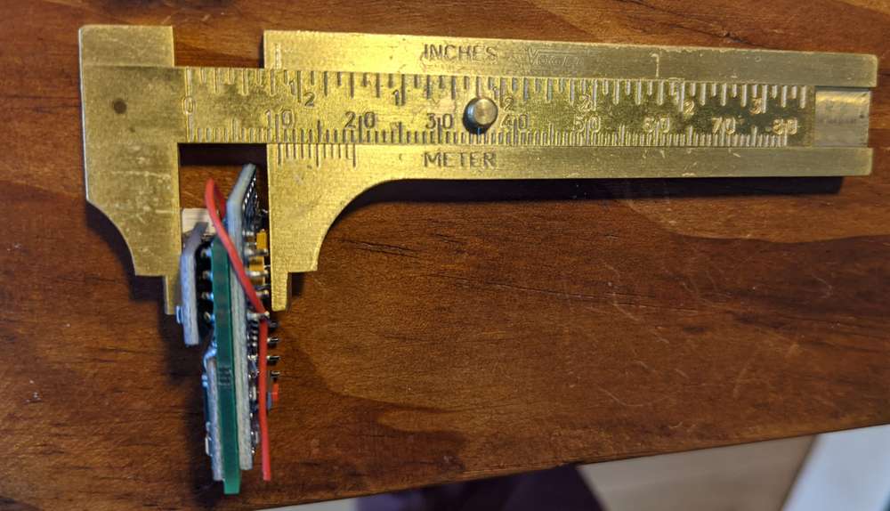
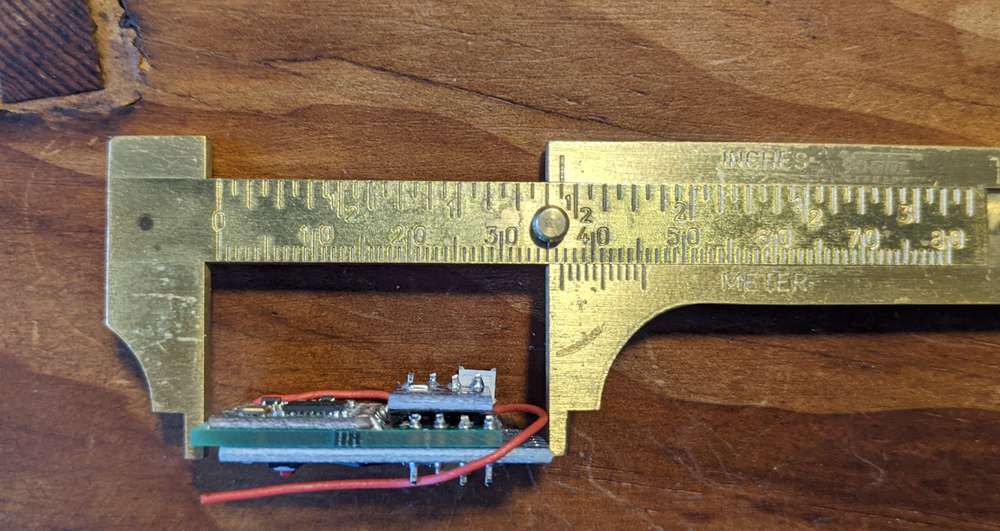
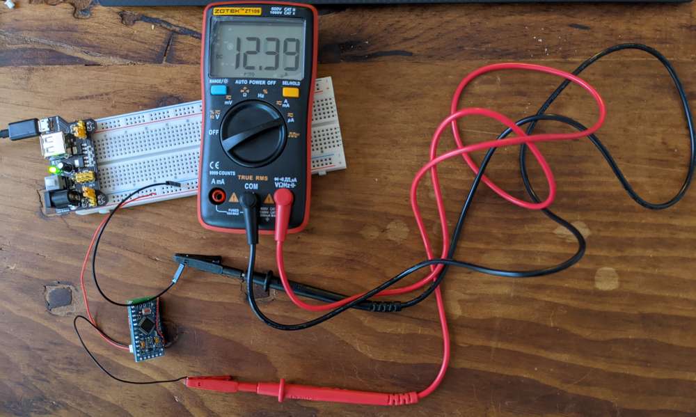
      Hi, with a newer, potentially better DMM I found 12.4Β΅A at 3.3V for a Pro Mini (3.3/8MHz, regulator and power LED removed, stock bootloader) with a BME280 (which has an additional, in this 3.3V setting unneeded, power regulator on board that could be removed) and a RFM95/96, at deep sleep.
      Also I got you some pic of the dimensions for that older version of the board I had lying around.
      Cheers, Joost

      PXL_20201121_121708555.jpg PXL_20201121_121643304.jpg ProMini-BME280-RFM95.jpg

      posted in OpenHardware.io
      Joost
      Joost
    • RE: πŸ’¬ Minimal LiPo powered Arduino Pro Mini + RFM95 MySensors node

      HI, I'll try to get back to you this weekend and re-measure my power consumption (you're correct, these are unmodified 8MHz/3.3V Pro Minis, no modified bootloader or anything). The consumption was measured with two relatively cheap multimeters, giving the same result (in comparison to your link without the DS18B20 and with a RFM95), though I'm pretty confident this would be kind of correct.

      Btw. you mean the thickness of the radio module on its own?

      posted in OpenHardware.io
      Joost
      Joost
    • RE: Thanks for node-red-contrib-mysensors and a question regarding collections or arrays

      This seems to evaluate to true/undefined every time, effectively resetting the array:

      var global_individual_data=global.get("global_invidual_data");
      if (global_individual_data===undefined) {
          msg.kein_array_vorhanden="true"
          global_individual_data=[];
      }
      

      even though it's later set with

      global.set("global_individual_data",global_individual_data);
      
      posted in Node-RED
      Joost
      Joost
    • RE: Thanks for node-red-contrib-mysensors and a question regarding collections or arrays

      HI, thanks, I guess right now the problem lies in the data storage in global or flow context.
      With this I can build the individual obejct, and pushing it on a global array gives no error. But the array is not properly stored and retrieved from the global context:

      var ind_data={};
      ind_data.nodeid=msg.nodeId;
      ind_data.type=msg.type;
      ind_data.payload=msg.payload;
      
      var global_individual_data=global.get("global_invidual_data");
      if (global_individual_data===undefined) {
          msg.kein_array_vorhanden="true"
          global_individual_data=[];
      }
      global_individual_data.push(ind_data);
      
      global.set("global_individual_data",global_individual_data);
      
      
      posted in Node-RED
      Joost
      Joost
    • RE: Thanks for node-red-contrib-mysensors and a question regarding collections or arrays

      Ok, with this I can at least create an individual data point object:

      var ind_data={};
      ind_data.nodeid=msg.nodeId;
      ind_data.type=msg.type;
      ind_data.payload=msg.payload;
      
      var global_individual_data=global.get("global_invidual_data");
      if (global_individual_data===undefined) {
          global_individual_data={};
      }
      global_individual_data.push(ind_data);
      

      But "pushing" this on to global_individual_data gives me an error. How could I store those indivudal objects in global context and iterate over them in a template node?

      posted in Node-RED
      Joost
      Joost
    • RE: Thanks for node-red-contrib-mysensors and a question regarding collections or arrays

      PS: this here

      var nodekey=msg.nodeId;var datatype=msg.type;var payload=msg.payload;
      //var individual_data={ nodekey, {datatype, payload}};
      var ind_data=[];
      ind_data.push[nodekey][datatype]=payload;
      
      var global_individual_data=global.get("global_invidual_data");
      if (global_individual_data===undefined) {
          global_individual_data={"node":0,"type":"voltage", "payload":3.3333 };
      }
      //global_individual_data.add(individual_data);
      //var nodekey=msg.nodeId;var datatype=msg.type;
      //global_individual_data[nodekey][datatype]=msg.payload;
      
      global.set("global_individual_data",global_individual_data);
      msg.global_individual_data=global_individual_data;


      is just my last non-working attempt and probably way way off (I know ind_data is not added to global_individual_data in there at this point); I have tried innumerable variations before with no success. I am pretty lost here...

      Debug log right now:

      10/25/2020, 8:52:05 AMnode: Store nodeIDs in arrayfunction : (error)
      "TypeError: Cannot set property 'humi' of undefined"
      10/25/2020, 8:52:05 AMnode: Store nodeIDs in arrayfunction : (error)
      "TypeError: Cannot set property 'pres' of undefined"
      10/25/2020, 8:52:05 AMnode: Store nodeIDs in arrayfunction : (error)
      "TypeError: Cannot set property 'volt' of undefined"
      
      posted in Node-RED
      Joost
      Joost
    • Thanks for node-red-contrib-mysensors and a question regarding collections or arrays

      Hi everyone,
      thanks for implementing node-red-contrib-mysensors, which works great and has rejuvenated my interest in MySensors! I find it a lot more accessible compared to others controllers like HomeAssistant, with which I always had problems in implementing my own sensors mainly due to hidden raw data in HomeAss (and others), also problems with persistence (which I did not want) etc etc. Node-Red is very transparent I think, and a great way to receive and process/display MySensor data.

      Now I am looking into getting my dashboard dynamic. I have a couple of MySensors nodes, which are pretty identical (apart from the nodeId), sending 4 childSensorIds of interest to me, based on which I also added a msg.type (temp, humi, pres or voltage). nodeIds are hardcoded in the sketch, so this does not need handling.

      What I would like to do is to show received data without any further ado, when a node is transmitting (meaning in my case when it has battery power).
      A node is transmiting -> data is presented in a table.
      A node is out of power -> entries are removed rsp. not shown in the table, are at least not updated anymore.
      A new node is added to the network -> data is automatically appended to the table.

      Table data might possibly be shown via a template node, see below.

      What I did not get now despite many tries is how to store the received sensor data in an array or collection, to iterate over this in the template node. I guess the strucutre would be to add an entry for every nodeId, and as "subentries" (key:values?) the type and msg.payload. All of this stored in global or flow context to be accessible by the template node.

      Now, anyone might have a hint how to declare the array/collection and how to store and update the sensor data? This is what I did not get to work, see below.

      Thanks everyone for any hints,

      Joost

      [
          {
              "id": "97bf2754.81864",
              "type": "debug",
              "z": "654a29b5.1136",
              "name": "",
              "active": true,
              "tosidebar": true,
              "console": false,
              "tostatus": false,
              "complete": "true",
              "targetType": "full",
              "statusVal": "",
              "statusType": "auto",
              "x": 370,
              "y": 380,
              "wires": []
          },
          {
              "id": "10894f66.719a01",
              "type": "ui_template",
              "z": "654a29b5.1136",
              "group": "38e6fc1d.b2f114",
              "name": "",
              "order": 17,
              "width": 0,
              "height": 0,
              "format": "<div ng-bind-html=\"msg.payload\"></div>\n\n<div layout=\"row\" layout-align=\"start center\">\n  <span flex>Node ID</span>\n  <span flex>Temp</span>\n  <span flex>Humi</span>\n  <span flex>Pres</span>\n  <span flex>Voltage</span>\n</div>\n<div layout=\"row\" layout-align=\"start center\" ng-repeat=\"individual_data in msg.global_individual_data\">\n  <span flex style=\"color: green\">{{individual_data.node}}</span>\n  <span flex style=\"color: red\">{{individual_data.node.humi}}</span>\n  <span flex style=\"color: black\">{{individual_data.node.pres}}%</span>\n  <span flex style=\"color: black\">{{individual_data.node.voltage}}</span>\n</div>",
              "storeOutMessages": true,
              "fwdInMessages": true,
              "resendOnRefresh": true,
              "templateScope": "local",
              "x": 380,
              "y": 340,
              "wires": [
                  []
              ]
          },
          {
              "id": "b98e0e8c.b686c",
              "type": "function",
              "z": "654a29b5.1136",
              "name": "Store nodeIDs in array",
              "func": "var nodeId_array=global.get(\"nodeId_array\");\nif (nodeId_array===undefined) {\n    nodeId_array=[];\n}\n\nif (! nodeId_array.includes(msg.nodeId)) {\n    nodeId_array.push(msg.nodeId);\n    global.set(\"nodeId_array\", nodeId_array);\n}\nmsg.nodeId_array=nodeId_array;\n\n//key=msg.nodeId+\".\"+msg.type;\n//var individual_data={ \"node\":msg.nodeId, \"type\":msg.type, \"payload\":msg.payload};\nvar nodekey=msg.nodeId;var datatype=msg.type;var payload=msg.payload;\n//var individual_data={ nodekey, {datatype, payload}};\nvar ind_data=[];\nind_data.push[nodekey][datatype]=payload;\n\nvar global_individual_data=global.get(\"global_invidual_data\");\nif (global_individual_data===undefined) {\n    global_individual_data={\"node\":0,\"type\":\"voltage\", \"payload\":3.3333 };\n}\n//global_individual_data.add(individual_data);\n//var nodekey=msg.nodeId;var datatype=msg.type;\n//global_individual_data[nodekey][datatype]=msg.payload;\n\nglobal.set(\"global_individual_data\",global_individual_data);\nmsg.global_individual_data=global_individual_data;\n\n//for (i=0;i<3;i++){\n//message=message+i; //add count to message\n//var newmsg={payload:message,topic:msg.topic}\n//    m_out.push(newmsg);\n//return[m_out];\n\nreturn msg;\n\n//local.count +=1;\n//msg.payload=\"F2 \"+msg.payload+\" \"+local.count;\n//context.set('data',local);\n",
              "outputs": 1,
              "noerr": 0,
              "initialize": "",
              "finalize": "",
              "x": 180,
              "y": 340,
              "wires": [
                  [
                      "10894f66.719a01",
                      "97bf2754.81864"
                  ]
              ]
          },
          {
              "id": "872133a5.70d8a8",
              "type": "function",
              "z": "654a29b5.1136",
              "name": "msg.topic according to childSensorId",
              "func": "switch (msg.childSensorId) {\n    case 0:\n        msg.topic = \"Node \" + msg.nodeId + \" Temp\";\n        msg.type=\"temp\";\n        break;\n    case 1:\n        msg.topic = \"Node \" + msg.nodeId + \" Humi\";\n       msg.type=\"humi\";\n        break;\n    case 2:\n        msg.topic = \"Node \" + msg.nodeId + \" Press\";\n        msg.type=\"pres\";\n        break;\n    case 9:\n        msg.topic = \"Node \" + msg.nodeId + \" Voltage\";\n        msg.type=\"volt\";\n        break;\n}\n\nvar datetimeJC = new Date();\nmsg.timestampJC = datetimeJC.getHours() + \":\" + ('00' + datetimeJC.getMinutes()).slice(-2);\n\nreturn msg;\n",
              "outputs": 1,
              "noerr": 0,
              "initialize": "",
              "finalize": "",
              "x": 190,
              "y": 260,
              "wires": [
                  [
                      "b359fbb4.3b12f",
                      "b98e0e8c.b686c"
                  ]
              ]
          },
          {
              "id": "ce62c592.b3c958",
              "type": "switch",
              "z": "654a29b5.1136",
              "name": "Filter childSensorIds",
              "property": "childSensorId",
              "propertyType": "msg",
              "rules": [
                  {
                      "t": "eq",
                      "v": "0",
                      "vt": "str"
                  },
                  {
                      "t": "eq",
                      "v": "1",
                      "vt": "str"
                  },
                  {
                      "t": "eq",
                      "v": "2",
                      "vt": "str"
                  },
                  {
                      "t": "eq",
                      "v": "9",
                      "vt": "str"
                  }
              ],
              "checkall": "false",
              "repair": false,
              "outputs": 4,
              "x": 240,
              "y": 140,
              "wires": [
                  [
                      "872133a5.70d8a8"
                  ],
                  [
                      "872133a5.70d8a8"
                  ],
                  [
                      "872133a5.70d8a8"
                  ],
                  [
                      "872133a5.70d8a8"
                  ]
              ]
          },
          {
              "id": "2434c5bc.48688a",
              "type": "mysdecode",
              "z": "654a29b5.1136",
              "database": "",
              "name": "",
              "mqtt": false,
              "enrich": false,
              "x": 290,
              "y": 40,
              "wires": [
                  [
                      "3d2bf478.a96f2c",
                      "ce62c592.b3c958"
                  ]
              ]
          },
          {
              "id": "d8a0a27c.b28218",
              "type": "serial in",
              "z": "654a29b5.1136",
              "name": "",
              "serial": "65ccd652.db113",
              "x": 70,
              "y": 40,
              "wires": [
                  [
                      "2434c5bc.48688a"
                  ]
              ]
          },
          {
              "id": "38e6fc1d.b2f114",
              "type": "ui_group",
              "z": "",
              "name": "Default",
              "tab": "d3c44e8c.f5c748",
              "order": 1,
              "disp": true,
              "width": "8",
              "collapse": true
          },
          {
              "id": "65ccd652.db113",
              "type": "serial-port",
              "z": "",
              "serialport": "/dev/ttyUSB0",
              "serialbaud": "38400",
              "databits": "8",
              "parity": "none",
              "stopbits": "1",
              "waitfor": "",
              "dtr": "none",
              "rts": "none",
              "cts": "none",
              "dsr": "none",
              "newline": "\\n",
              "bin": "false",
              "out": "char",
              "addchar": "",
              "responsetimeout": "10000"
          },
          {
              "id": "d3c44e8c.f5c748",
              "type": "ui_tab",
              "z": "",
              "name": "JC_Dashboard",
              "icon": "dashboard",
              "disabled": false,
              "hidden": false
          }
      ]
      
      posted in Node-RED
      Joost
      Joost
    • RE: How do commercial products achieve continuous receive (like in battery powered wireless weather stations)?

      @Puneit-Thukral
      Hi, thanks, checked again, but I did not find any battery operated receiving sensors there; also search did not give any results related to "receive" and other terms alike.
      Mind sharing a link or two?

      posted in General Discussion
      Joost
      Joost
    • RE: RFM69/95 won't run

      Is the SX1278 working with the RFM95 driver as well? All my boards are SX1276 and have a different pinout/PCB formfactor...

      posted in Hardware
      Joost
      Joost
    • RE: Is soldering castellated pads on THT pads feasible?

      @Joost Added two photos to the project page. KiCAD/rendering still to follow.

      posted in Hardware
      Joost
      Joost
    • RE: Is soldering castellated pads on THT pads feasible?

      Hi,

      just a quick feedback on this; I tried it now with two boards and so far it works pretty well. I'll keep using this technique for my minimal nodes for now. Those are by no means "mission critical" in any way, so a possible failure at some point won't pose a major problem.
      I'll probably post a picture on my openhardware.io entry in the coming days.
      Bye, Joost

      posted in Hardware
      Joost
      Joost
    • How do commercial products achieve continuous receive (like in battery powered wireless weather stations)?

      Hi everyone,

      I wonder how more or less cheap commercial products like e.g. wireless weather stations (often 433MHz) achieve a continuous wireless connection with both parties battery powered?
      So far this looks impossible to me with RFM95 or NRF24; is the implemented hardware in those products that different? Or are there other tricks I could implement myself in own products (short transceive windows come to mind, probably necessitating some form of synchronization)?

      Bye,

      Joost

      posted in General Discussion
      Joost
      Joost
    • RE: Getting Pin Change Interrupts working together with Timer interrupts / sleep(XX ms) on Arduino Pro Mini

      @Yveaux & others:
      So this works great! Here is an example sketch to get Pin Change Interrupts working together with timer-based sleep(). There will be identification of the triggered pin as well as discrimination between rising and falling edge. To test, just add a jumper wire to pin A1 or/and A2 to a Arduino Pro Mini and short it to Ground to wake the Arduino out of a timed sleep() (a connected Radio, here a RFM95, is needed to get the sketch started).

      #include <Arduino.h>
      
      #define MY_RADIO_RFM95
      #include <MySensors.h>
      
      volatile int isrcounter = 0, timercounter=0;
      volatile char PinRegLast, ChangedPin, PinRegister;
      volatile boolean isr_interrupted;
      uint32_t remainingSleepTime = 0;
      
      ISR(PCINT1_vect)
      {
          PinRegister = PINC;
          ChangedPin = PinRegister ^ PinRegLast;
          PinRegLast = PinRegister;
          _wokeUpByInterrupt = 0xFE;
          isr_interrupted=true;
          isrcounter++;
      }
      
      void setup()
      {
      noInterrupts();
      PCICR |= 0b00000011; // Enables Ports B and C Pin Change Interrupts
      PCMSK1 |= 0b00000110; //PCINT9 & PCINT10 = A1 & A2
      PCIFR  = B00000001; // Reset Interruptflag
      pinMode(A1, INPUT_PULLUP); pinMode(A2, INPUT_PULLUP);
      PinRegister = PINC;
      interrupts();
      Serial.begin(38400);
      }
      
      void presentation() {}
      
      void loop()
      {
        noInterrupts();
        if ( isr_interrupted ) {
          isr_interrupted = false;
          switch (ChangedPin){
          case (1 << PINC1):
            if (~PinRegister & (1 << PINC1)) { 
              Serial.print("Interrupted / Woken up by Pin A1, remaining sleep() time: ");  
              remainingSleepTime = getSleepRemaining();
              Serial.println( remainingSleepTime );}
            else { 
              Serial.println("Falling edge of Pin A1"); 
             } 
            break;
          case (1 << PINC2):
            if (~PinRegister & (1 << PINC2)) { 
              Serial.print("Interrupted / Woken up by Pin A2, remaining sleep() time: "); 
              remainingSleepTime = getSleepRemaining();
              Serial.println( remainingSleepTime );}
            else { 
              Serial.println("Falling edge of Pin A2"); 
             }
            break;
          default:
            break;
          interrupts();
          }
        }
        else  { 
          interrupts();
          Serial.println("Timer wake up / Loop"); 
          timercounter++; 
          }
      
        Serial.print("  ");  Serial.print(" ISR Counter: ");Serial.print(isrcounter);  Serial.print("   Timer counter: "); Serial.println(timercounter);
        sleep((uint32_t) 60*1000);
      }
      

      Thanks a lot! Joost

      posted in Troubleshooting
      Joost
      Joost
    • RE: Getting Pin Change Interrupts working together with Timer interrupts / sleep(XX ms) on Arduino Pro Mini

      @Yveaux said in Getting Pin Change Interrupts working together with Timer interrupts / sleep(XX ms) on Arduino Pro Mini:

      @Joost as documented it can be roughly 8 seconds off on avr. When an avr is set to sleep for 8 seconds (the maximum watchdog sleep time) and it is woken by an interrupt, it will not know how much time is remaining and always return the same time remaining.
      Try sleeping for a minute, then interrupt after 1 second and after half a minute. The remaining time should be different.

      @Yveaux Hi, yeah, I was already expecting the 8s inaccuracy (which is no problem at all, I am planning to cover intervals of several hours).
      I tried yesterday night with sleep times of 1-5 minutes and could not get it to work at that point (always receiving identical numbers though the time to awakening the node with PCInt differed), but this might be because I just hacked it in an otherwise more complicated sketch.

      I'll start now with making up a minimal test sketch to get the hang of it!
      Thanks, J

      posted in Troubleshooting
      Joost
      Joost
    • RE: Getting Pin Change Interrupts working together with Timer interrupts / sleep(XX ms) on Arduino Pro Mini

      @Yveaux Thanks, very cool and promising, will take a more in depth look tomorrow!
      I just threw that in my code quickly tonight, so far I got a 5 digit number back, but that was always the same also with different wake up delays via PCInt after going to sleep().

      posted in Troubleshooting
      Joost
      Joost
    • RE: Getting Pin Change Interrupts working together with Timer interrupts / sleep(XX ms) on Arduino Pro Mini

      @zboblamont Thanks, will think about that if a pure software approach fails! Though I'd really like to keep complexity down; I'm planning on fabricating at least 10-20 nodes of that kind (by hand).

      posted in Troubleshooting
      Joost
      Joost
    • RE: Getting Pin Change Interrupts working together with Timer interrupts / sleep(XX ms) on Arduino Pro Mini

      How does MySensors accomplish long sleep() times? Is it like
      sleep() with Watchdog Timer set for 8s -> calculate remainder -> sleep() again?
      If so, I could maybe find the var in which MySensors itself keeps track of sleep time.

      posted in Troubleshooting
      Joost
      Joost
    • RE: Getting Pin Change Interrupts working together with Timer interrupts / sleep(XX ms) on Arduino Pro Mini

      @zboblamont Ah, ok.
      To be honest, I had hoped there'd be a counter/register (for the timer interrupt - how does the Arduino keep track of itself otherwise?) I could read and then sleep() for the remainder...

      I'll browse around later and see if I can dig up something on the web.
      Thanks!

      posted in Troubleshooting
      Joost
      Joost
    • RE: Is soldering castellated pads on THT pads feasible?

      @sundberg84 Yes, but I wonder if it will also work if I use the regular (round) THT pads from the Pro Mini (as the cheapest and most widely found Pro Minis seem to be like these)

      I'll probably just try it I guess, but of course have to adapt my PCB accordingly to get the castellated half holes. Hope my PCB manufacturer knows what to do with the KiCAD file.

      posted in Hardware
      Joost
      Joost
    • Is soldering castellated pads on THT pads feasible?

      Hi guys,

      in my minimal MySensors node I use pins in THT for connecting the Arduino to my PCB.

      Now I wonder if it might work well to use castellated pads on my PCB and solder them on the backside of the Arduino on the respective THT pads, getting rid of the pins for good (saving manufacturing time / material / weight / size).

      Do you think this would give a stable connection?

      Thanks & bye,

      Joost

      posted in Hardware
      Joost
      Joost
    • RE: Getting Pin Change Interrupts working together with Timer interrupts / sleep(XX ms) on Arduino Pro Mini

      Thanks, will recap your code for identifying the pressed button, seems pretty concise.
      Though this code in general will in my experience not work together with a "timed" sleep() - you have sleep(...,0), and my goal is to get PCInterrupts and Timer interrupts working together.

      After some ongoing testing, the sketch I posted above works in achieving both.
      Now I still have to figure out a way how to sleep() for the remaining sleep interval after the node was awoken with a button press /PCInt (say, I want a sensor reading strictly every 4 hours (sleep(4 * 60 * 60 * 1000), but wake the node after 90minutes with a button press. Now I'd need a way to figure out the remainder of the sleep interval (2.5h)).
      Thanks,

      Joost

      posted in Troubleshooting
      Joost
      Joost
    • RE: πŸ’¬ Minimal LiPo powered Arduino Pro Mini + RFM95 MySensors node

      Thanks! I'm looking for a way to upload the FreeCad Files here, but so far the Website does not allow uploading of unknown file types (like *.Fcstd). Cheers!

      posted in OpenHardware.io
      Joost
      Joost
    • RE: Getting Pin Change Interrupts working together with Timer interrupts / sleep(XX ms) on Arduino Pro Mini

      This is the complete sketch:

      #include <Arduino.h>
      
      #define MY_RADIO_RFM95
      #include <MySensors.h>
      
      volatile int isrcounter = 0, timercounter=0;
      volatile char PinRegLast, ChangedPin, PinRegister;
      volatile unsigned long last_debounce_time=0;
      volatile boolean isr_interrupted;
      
      ISR(PCINT1_vect)
      {
          PinRegister = PINC;
          ChangedPin = PinRegister ^ PinRegLast;
          PinRegLast = PinRegister;
          _wokeUpByInterrupt = 0xFE;
          isr_interrupted=true;
          isrcounter++;
      }
      
      void setup()
      {
      noInterrupts();
      PCICR |= 0b00000011; // Enables Ports B and C Pin Change Interrupts
      PCMSK1 |= 0b00000110; //PCINT9 & PCINT10 = A1 & A2
      PCIFR  = B00000001; // Reset Interruptflag
      pinMode(A1, INPUT_PULLUP); pinMode(A2, INPUT_PULLUP);
      PinRegister = PINC;
      interrupts();
      Serial.begin(38400);
      }
      
      void presentation() {}
      
      void loop()
      {
        noInterrupts();
        if ( isr_interrupted ) {
          isr_interrupted = false;
          switch (ChangedPin){
          case (1 << PINC1):
            if (~PinRegister & (1 << PINC1)) { Serial.println("Interrupted / Woken up by Pin A1"); } 
            else Serial.println("Falling edge of Pin A1"); 
            break;
          case (1 << PINC2):
            if (~PinRegister & (1 << PINC2)) { Serial.println("Interrupted / Woken up by Pin A2"); } 
            else Serial.println("Falling edge of Pin A2"); 
            break;
          default:
            break;
          }
        }
        else  { Serial.println("Timer wake up / Loop"); timercounter++; }
        interrupts();
      
        Serial.print("  ");  Serial.print(" ISR Counter: ");Serial.print(isrcounter);  Serial.print("   Timer counter: "); Serial.println(timercounter);
        sleep((uint32_t) 60*1000);
      }
      

      Does anyone spot obvious mistakes in here?
      In basic testing this seems to work fine, though I haven't "fuzzed" it (like fast repeating button switching for example).

      posted in Troubleshooting
      Joost
      Joost
    • RE: Getting Pin Change Interrupts working together with Timer interrupts / sleep(XX ms) on Arduino Pro Mini

      Thanks guys!

      I've been experimenting with a small addition to the ISR

      ISR(PCINT1_vect)
      {
          _wokeUpByInterrupt = 0xFE;
          interrupted=true;
          isrcounter++;
      }


      for the last hour and am cautiously optimistic this might work. I believe that's also the main thought of the thread you linked to @olka , thanks for that! Will let you know if this works out in a stable fashion,

      Joost

      PS: using diodes is a great idea as well, but as my PCB is already finished and on my table right now I'd prefer getting around with a proper software solution πŸ™‚ ...

      posted in Troubleshooting
      Joost
      Joost
    • RE: Getting Pin Change Interrupts working together with Timer interrupts / sleep(XX ms) on Arduino Pro Mini

      So I did some further testing. If I set the sleep(time) to

      1 Minute: I have to close the contact for 4 times before the ISR returns to loop(). Variable counter then contains 8.

      2 Minutes: The contact needs to be closed 8 times before the ISR retuns to loop(); counter is then 16 (= rising and falling change of each contact closure; also meaning there is absolutely no bouncing at all)

      4 Minutes: 16 contact closures are needed, counter as now expected gets up to 32.

      What's happening here??

      posted in Troubleshooting
      Joost
      Joost
    • RE: Getting Pin Change Interrupts working together with Timer interrupts / sleep(XX ms) on Arduino Pro Mini

      Hi,

      yes, this is no bouncing issue. I'll try to rephrase / explain exactly what's happening.

      Scenario 1, sleep time 60*1000ms:

      • Node goes to sleep(60*1000)
      • I close and open contact for the first time (1) -> no wakeup
      • Wait for a second or so
      • Closing/Opening secord time (2) -> no wakeup
      • Waiting ... Closing/Opening third/fourth/fifth time
      • Now the node wakes up, gives me "Interrupted / Woken up by Pin" and a counter of 9 to 11 (slightly varying)

      In scenario 2 with longer sleep time of say 10 minutes, I have to close and open the contact/button for 30 to 40 times until the node wakes up, but then giving me the message that counter got incremented 77 times - which means the ISR got triggered that often, but the node did not resume into loop() all those wakeups. Why it decides to resume loop() at that point is beyond me. It should just resume loop() at the first ISR call.
      This seems so strange...

      I did another test, which I sure know is wrong usage of ISRs, but shows that the ISR is triggered: if I call loop() in my ISR (I know this is wrong...), every button press is immediately registered.

      posted in Troubleshooting
      Joost
      Joost
    • Getting Pin Change Interrupts working together with Timer interrupts / sleep(XX ms) on Arduino Pro Mini

      Hi everyone,

      this is a recap of another recent thread to get this into the correct subforum and to clean up the info.
      For my minimalistic battery powered node (Minimal LiPo powered Arduino Pro Mini + RFM95 MySensors node) I am (of course:-) using MySensors, together with its sleep() function. Now I am looking to get timer wake ups and additional wake ups via Pin Change Interrupts working.

      The minimal hardware set up to test this consists of an Arduino (I use a Pro Mini 3.3V/8MHz) with a simple wire connected to A1, which can then be connected to ground to simulate a button press. I believe debouncing etc. is not necessary for this example, as I just want to wake up the Arduino (mind you, which should be sleeping via sleep(XX ms), not indefintely) successfully and will figure out the rest later on.

      The most simplistic example code I could come up with:

      #include <Arduino.h>
      
      #define MY_RADIO_RFM95
      #include <MySensors.h>
      
      volatile int value = 1000, counter = 0;
      volatile char PinRegLast, ChangedPin, PinRegister;
      volatile unsigned long last_debounce_time=0;
      volatile boolean interrupted;
      
      ISR(PCINT1_vect)
      {
          interrupted=true;
          counter++;
      }
      
      void setup()
      {
      noInterrupts();
      PCICR |= 0b00000011; // Enables Ports B and C Pin Change Interrupts
      PCMSK1 |= 0b00000110; //PCINT9 & PCINT10 = A1 & A2
      interrupts();
      pinMode(A1, INPUT_PULLUP); pinMode(A2, INPUT_PULLUP);
      Serial.begin(38400);
      }
      
      void presentation() {}
      
      void loop()
      {
        noInterrupts();
        if ( interrupted ) {
          Serial.println("Interrupted / Woken up by Pin");
          interrupted = false;
        }
        else  { Serial.println("Timer wake up / Loop");  }
      
        Serial.print("  ");  Serial.print(" Counter: ");Serial.println(counter); 
        interrupts();
        sleep((uint32_t) 10*60*1000);
        //LowPower.powerDown(SLEEP_FOREVER, ADC_OFF, BOD_OFF); //not compiling
      }
      

      This misbehaves in a strange way. First of all, it seems to do a timed sleep()/wake up correctly. But simulating button presses does not wake the node immediately, but with varying repetitions of button presses which depend on the duration of the requested sleep(XXms) time.

      With sleep((uint32_t) 10 * 60 * 1000), the node wakes up after approx 35 button presses and I get:

      Timer wake up / Loop
         Counter: 0
      Interrupted / Woken up by Pin
         Counter: 77
      Interrupted / Woken up by Pin
         Counter: 152
      

      With sleep((uint32_t) 60 * 1000) on the other hand, much less repetitions are needed (mostly 4 button presses) and I get:

      Interrupted / Woken up by Pin
         Counter: 11
      Interrupted / Woken up by Pin
         Counter: 20
      Interrupted / Woken up by Pin
         Counter: 30
      Interrupted / Woken up by Pin
         Counter: 40
      Interrupted / Woken up by Pin
         Counter: 49
      

      The interval of 9-10 counter increments is pretty stable (but not always the same) with this sleep duration, as are the counter increments of 75-80 with the longer sleep time above.

      So depending on the requested sleep time, the delay resp. the iterations before the ISR wakes up the node to get into the loop() is longer or shorter. What might cause this?

      Thanks for any help,

      Joost

      BTW: thanks again to @electrik , @mfalkvidd, @BearWithBeard from my first thread for helping. Sadly, the Low-Power lib approach is not working (anymore) as id does not compile in conjunction with MySensors 2.3.2 (Github issue).

      posted in Troubleshooting
      Joost
      Joost
    • RE: Pro Mini + RFM95 and two ISR-watched buttons possible?

      PS: one downside will probably be not being able to wake up programmatically and double the node as a e.g. temperature / climate sensor, as I had in mind.

      Sorry for the confusion above, too little sleep in the last days (at least I hope that explains it πŸ™‚ )

      Perhaps @Yveaux can help here on how to combine pin change interrupts and timer wake into a successful sleep() command? So far it looks like that would be possible with Low-Power lib, but this is not compiling in conjunction with MySensors 2.3.2.

      posted in General Discussion
      Joost
      Joost
    • RE: Pro Mini + RFM95 and two ISR-watched buttons possible?

      *** Edit: sorry, all below seems to be wrong / misuse of sleep(); see end of linked thread from 2017

      Some news: I found this comment https://forum.mysensors.org/post/56372 by @DavidZH who possibly described what I seem to be seeing as well (no wakeups via PinChangeInterrupt when using MySensors sleep() function as posted above) and who also posted a workaround (thanks David for posting this in 2017!!):

      sleep(0xff,0x00, 0xff, 0x00, 0); 
      

      Quote: "...As soon as I change any of the parameters, the node will not wake up anymore...."

      Now indeed my node can be woken via PinChangeInterrupts on Pin A1 and A2 and is down to some unbelievable 1microAmp in between (by means of a cheap Multimeter) with no radio/transport initialization so far.
      So, with just preliminary testing so far this might be the solution (did not check radio transmission after interrupts for now).
      Could someone shed some light on what these parameters do to the sleep function? Looked here of course https://www.mysensors.org/download/sensor_api_20#sleeping but couldn't make sense out of 0xFF, 0x00 .
      Thanks everyone,

      Joost

      ********************** End of edit

      posted in General Discussion
      Joost
      Joost
    • RE: Pro Mini + RFM95 and two ISR-watched buttons possible?

      Well, seems MySensors and the Low-Power lib in its latest revisions don't play nice together, bummer...

      Getting

      Compiling .pio/build/pro8MHzatmega328/src/main.cpp.o
      Linking .pio/build/pro8MHzatmega328/firmware.elf
      LowPower.cpp.o (symbol from plugin): In function `LowPowerClass::idle(period_t, adc_t, timer2_t, timer1_t, timer0_t, spi_t, usart0_t, twi_t)':
      (.text+0x0): multiple definition of `__vector_6'
      .pio/build/pro8MHzatmega328/src/main.cpp.o (symbol from plugin):(.text+0x0): first defined here
      collect2: error: ld returned 1 exit status
      *** [.pio/build/pro8MHzatmega328/firmware.elf] Error 1
      

      and it looks like I'm not the only one: πŸ˜•
      Github issue

      posted in General Discussion
      Joost
      Joost
    • RE: Pro Mini + RFM95 and two ISR-watched buttons possible?

      @BearWithBeard Thanks; will look into this as well.
      Seems to me that the main difference is your sleep(0) vs. my sleep(16000), but who knows, perhaps that makes a difference. Btw, I believe Pin2 with the attached IRQ is obligatory for RFM95 radios (at least it's the default in MySensors, and I designed my PCB according to this).

      posted in General Discussion
      Joost
      Joost
    • RE: Pro Mini + RFM95 and two ISR-watched buttons possible?

      @mfalkvidd Will look into this tonight or tomorrow; just as a quick note for me and potentially others:
      Just found this thread with a very professional looking sketch by the author which seems a solid base to start upon:

      https://forum.mysensors.org/topic/5704/rfm95-sleep-mode/6

      Seemingly important parts from the sketch ( https://github.com/trlafleur/Soil_Moisture_Sensor_MS_R1.1-RFM95/blob/master/Soil_Moisture_Sensor_MS_R1.1-RFM95.ino ) :

      void systemSleep()
      {
          debug1(PSTR("\n*** Going to Sleep ***\n"));
          wait (100);
          // put led's, radio and flash to sleep
          // Turn off LED's
          pinMode (MY_DEFAULT_TX_LED_PIN, INPUT);
          pinMode (MY_DEFAULT_RX_LED_PIN, INPUT);
          pinMode (MY_DEFAULT_ERR_LED_PIN, INPUT);
          pinMode (OnBoardLed, INPUT); 
          
          // Put Flash to sleep
          
      
          // Put Radio and transport to Sleep
          transportPowerDown();               // Shut down radio and MySensor transport
          
          interrupts();                       // make sure interrupts are on...
          LowPower.standby();                 // SAMD sleep from LowPower systems
          
             //  .... we will wake up from sleeping here if triggered from an interrupt
          interrupts();                       // make sure interrupts are on...                                      
      }
      
      /* **************** System Wake-up from Sleep ******************* */
      void systemWakeUp() 
      {                                          
          
      //  re enable LED's if needed
      //    pinMode (MY_DEFAULT_TX_LED_PIN, OUTPUT);
      //    pinMode (MY_DEFAULT_RX_LED_PIN, OUTPUT);
      //    pinMode (MY_DEFAULT_ERR_LED_PIN, OUTPUT);
      //    pinMode (OnBoardLed, OUTPUT);  
      
          // wake up Flash if needed
      
          // wake up MySensor transport and Radio from Sleep
          //transportInit();
          hwSleep(1);                         // as MySensor had NO sleep or Watch Dog for SAMD, this will
                                              // wake us up so that we can send and receive messages
          while (!isTransportReady()) {       // Make sure transport is ready
          _process(); }
      
          interrupts();                       // make sure interrupts are on...
      }
      
      posted in General Discussion
      Joost
      Joost
    • RE: Pro Mini + RFM95 and two ISR-watched buttons possible?

      @mfalkvidd Thanks, will try that.
      TBH I had seen that already in there, but hoped it would not be needed anymore (since that sketch is from 2016).
      Would I need to power down my RFM95 radio like it is done with the NRF24?
      Don't want to loose my 9microAmp sleeping current πŸ™‚

      Will get back with results tomorrow,

      Joost

      posted in General Discussion
      Joost
      Joost
    • RE: Pro Mini + RFM95 and two ISR-watched buttons possible?

      Hi everybody,
      thanks for you help, I got as far as this:

      #include <Arduino.h>
      #include <avr/interrupt.h>
      
      #define MY_RADIO_RFM95
      #include <MySensors.h>
      
      volatile int value = 1000;
      volatile char PinRegLast, ChangedPin, PinRegister;
      volatile unsigned long last_debounce_time=0;
      
      void setup()
      {
      noInterrupts();
      PCICR |= 0b00000011; // Enables Ports B and C Pin Change Interrupts
      PCMSK1 |= 0b00000110; //PCINT9 & PCINT10 = A1 & A2
      PCMSK1 |= 0b00001000; // PCINT11
      PCIFR  = B00000001; // Reset Interruptflag
      interrupts();
      pinMode(A1, INPUT_PULLUP); pinMode(A2, INPUT_PULLUP);
      Serial.begin(38400);
      }
      
      void presentation() {}
      
      void loop()
      {
        //_wokeUpByInterrupt = INVALID_INTERRUPT_NUM;
        Serial.print(value); Serial.print(" : ");Serial.println(PinRegister, BIN);
        sleep(160000);
      }
      
      ISR(PCINT1_vect)
      {
        if ( (long) millis() - last_debounce_time > 30)
        {
          //_wokeUpByInterrupt = 0xFE;
          PinRegister = PINC;
          ChangedPin = PinRegister ^ PinRegLast;
          PinRegLast = PinRegister;
          switch (ChangedPin){
          case (1 << PINC1):
            if (~PinRegister & (1 << PINC1)) value++;
            break;
          case (1 << PINC2):
            if (~PinRegister & (1 << PINC2)) value--;
            break;
          default:
            break;
          }
          last_debounce_time = millis();
      
        }
      }


      When I have this code without the MySensors parts (e.g. #inclue MySensors.h & sleep(..)) in it running, it kind of works plus/minus some debouncing issues. But when including MySensors and sleeping in loop(), there is rarely a reaction to pin changes and at no time a change of the variable "value", which is working without the MySensors bits in there.

      Is there something special to deal with when using sleep() together with PinChangeInterrupts?

      posted in General Discussion
      Joost
      Joost
    • RE: Pro Mini + RFM95 and two ISR-watched buttons possible?

      Thanks very much! Will start looking into this now!

      posted in General Discussion
      Joost
      Joost
    • RE: Pro Mini + RFM95 and two ISR-watched buttons possible?

      Thanks very much for pointing me the way and linking all those docs/references!

      I'll try to make up a working example and leave it here as reference,
      bye,

      Joost

      posted in General Discussion
      Joost
      Joost
    • Pro Mini + RFM95 and two ISR-watched buttons possible?

      Hi everyone,

      as connecting a RFM95 radio uses Arduino digital pin 2, I am wondering if it is possible to use another pin besides pin 3 to get two ISR watched buttons connected to one node? I am looking into building general MySensor based remotes for controlling music, lights and other connected DIY hardware via MyController. In this scenario, only having a single button per battery powered node would be kind of inefficient.

      Thanks everyone for any clues,

      Joost

      Arduino ref regarding ISRs

      posted in General Discussion
      Joost
      Joost
    • RE: [Solved] Small problem with getting RSSI in an otherwise working RFM95 setup

      @tekka Thanks a lot!

      posted in Troubleshooting
      Joost
      Joost
    • RE: [Solved] Small problem with getting RSSI in an otherwise working RFM95 setup

      @tekka
      Hi, thanks a ton, this was the missing piece! Working great now!

      I started with the "official" example sketch out of the MySensors codebase

      https://github.com/mysensors/MySensors/blob/master/examples/RFM69_RFM95_ATC_SignalReport/RFM69_RFM95_ATC_SignalReport.ino ,

      where I did not see any reference to

      #define MY_SIGNAL_REPORT_ENABLED
      

      Did I overlook something or is this example sketch not working on its own in the current form?

      Thanks again very much for your help, best regards,

      Joost

      posted in Troubleshooting
      Joost
      Joost
    • RE: [Solved] Small problem with getting RSSI in an otherwise working RFM95 setup

      Hi,

      maybe anyone around here is running a RFM95 setup and could possibly test if they get credible output out of transportGetSignalReport(X) with the RFM95 driver?
      Any other ideas?

      Thanks everyone for working on / helping with MySensors!

      posted in Troubleshooting
      Joost
      Joost
    • RE: (Solved) S_Multimeter in HomeAssistant

      @Boots33 Wow, that's it!! I would never have found this by myself (as numerous hours of trial and error have already proven)... Thank you very much for staying with me and finally finding the solution!!

      So, I'm pretty relieved to finally have this working and am just left wondering why oh why there is a default to a (deprecated?) Mysensors API version, with so little notice regarding this detail in the setup instructions...

      Thanks again,

      Joost

      posted in Home Assistant
      Joost
      Joost
    • RE: (Solved) S_Multimeter in HomeAssistant

      Just a quick addition esp. withregard to @Boots33 :
      Also followed your advice and edited the persistence file while HASS was in persistence:false mode and filled in your fields.

      When I restarted, I got this in my log:

      020-02-17 22:15:40 DEBUG (MainThread) [mysensors] Receiving 121;0;1;0;38;3.38
      2020-02-17 22:15:40 DEBUG (MainThread) [homeassistant.components.mysensors.gateway] Node update: node 121 child 0
      2020-02-17 22:15:40 WARNING (MainThread) [homeassistant.components.mysensors.helpers] Child type 30 is not supported
      2020-02-17 22:15:42 DEBUG (SyncWorker_11) [mysensors.persistence] Saving sensors to persistence file /config/mysensors.json
      

      I concluded from this that the persistence file edit was successfull (HASS knows about the child id now), but somehow the child type 30 (which I suppose corresponds to S_Multimeter as in MySensors Serial API) is for whatever reason not supported by my installation (?? - this is a hassio on a raspberry 3, updated to latest HASS version.

      posted in Home Assistant
      Joost
      Joost
    • RE: (Solved) S_Multimeter in HomeAssistant

      Hi everybody,

      first of all please excuse that I didn't get back here. I was completely expecting to get email notifications for replies, but it seems I turned that off (or it is not switched on by default, can not remember). Very sorry and also thankful for your replies, which help me check my code against your working examples and rule out mistakes in my sketch.

      So, my journey to get this working continues. My current workflow to test new iterations is like this (I guess you were on the right track @maghac ) :

      1. Set persistence to false for mysensors integration.

      2. Restart HASS and check it's really off: yep, all nodes notified as "unknown"

      3. Power on the node I am testing with to get a new presentation to HASS. The log for this is

      2020-02-17 20:35:48 WARNING (MainThread) [mysensors] Node 105 is unknown
      2020-02-17 20:35:48 DEBUG (MainThread) [mysensors] Receiving 105;255;3;0;0;33
      2020-02-17 20:35:48 WARNING (MainThread) [mysensors] Node 105 is unknown
      2020-02-17 20:35:57 DEBUG (MainThread) [mysensors] Receiving 131;0;1;0;0;19.9
      2020-02-17 20:35:57 WARNING (MainThread) [mysensors] Node 131 is unknown
      2020-02-17 20:35:57 DEBUG (MainThread) [mysensors] Receiving 131;1;1;0;1;51.9
      2020-02-17 20:35:57 WARNING (MainThread) [mysensors] Node 131 is unknown
      2020-02-17 20:35:57 DEBUG (MainThread) [mysensors] Receiving 131;2;1;0;4;1009.23
      2020-02-17 20:35:57 WARNING (MainThread) [mysensors] Node 131 is unknown
      2020-02-17 20:35:57 DEBUG (MainThread) [mysensors] Receiving 131;9;1;0;24;3.36
      2020-02-17 20:35:57 WARNING (MainThread) [mysensors] Node 131 is unknown
      2020-02-17 20:36:00 DEBUG (MainThread) [mysensors] Receiving 131;255;3;0;0;79
      2020-02-17 20:36:00 WARNING (MainThread) [mysensors] Node 131 is unknown
      
      
      2020-02-17 20:36:11 DEBUG (MainThread) [mysensors] Receiving 121;255;0;0;17;2.3.2
      2020-02-17 20:36:11 DEBUG (MainThread) [homeassistant.components.mysensors.gateway] Node update: node 121 child 255
      2020-02-17 20:36:11 DEBUG (MainThread) [mysensors] Receiving 121;255;3;0;6;0
      2020-02-17 20:36:11 DEBUG (MainThread) [mysensors] Sending 121;255;3;0;6;M
      2020-02-17 20:36:11 DEBUG (MainThread) [mysensors] Receiving 121;255;3;0;11;BME280 Voltmeter 
      2020-02-17 20:36:11 DEBUG (MainThread) [homeassistant.components.mysensors.gateway] Node update: node 121 child 255
      2020-02-17 20:36:11 DEBUG (MainThread) [mysensors] Receiving 121;255;3;0;12;1.0.1
      2020-02-17 20:36:11 DEBUG (MainThread) [homeassistant.components.mysensors.gateway] Node update: node 121 child 255
      2020-02-17 20:36:11 DEBUG (MainThread) [mysensors] Receiving 121;9;0;0;30;Batt
      2020-02-17 20:36:11 WARNING (MainThread) [mysensors] Not a valid message: Not valid message sub-type: 30 for dictionary value @ data['sub_type']
      2020-02-17 20:36:11 DEBUG (MainThread) [mysensors] Receiving 121;0;0;0;6;Temperatur
      2020-02-17 20:36:11 DEBUG (MainThread) [homeassistant.components.mysensors.gateway] Node update: node 121 child 0
      2020-02-17 20:36:12 DEBUG (MainThread) [mysensors] Receiving 121;1;0;0;7;Luftfeuchtigkeit
      2020-02-17 20:36:12 DEBUG (MainThread) [homeassistant.components.mysensors.gateway] Node update: node 121 child 1
      2020-02-17 20:36:12 DEBUG (MainThread) [mysensors] Receiving 121;2;0;0;8;Luftdruck
      2020-02-17 20:36:12 DEBUG (MainThread) [homeassistant.components.mysensors.gateway] Node update: node 121 child 2
      2020-02-17 20:36:12 DEBUG (MainThread) [mysensors] Receiving 121;9;1;0;38;3.43
      2020-02-17 20:36:12 WARNING (MainThread) [mysensors] Child 9 is unknown
      2020-02-17 20:36:13 DEBUG (MainThread) [mysensors] Receiving 121;255;3;0;0;90
      2020-02-17 20:36:13 DEBUG (MainThread) [homeassistant.components.mysensors.gateway] Node update: node 121 child 255
      2020-02-17 20:36:13 DEBUG (MainThread) [mysensors] Receiving 121;2;1;0;4;1008.92
      2020-02-17 20:36:13 DEBUG (MainThread) [homeassistant.components.mysensors.gateway] Node update: node 121 child 2
      2020-02-17 20:36:13 INFO (MainThread) [homeassistant.components.mysensors] Adding new devices: [<Entity BME280 Voltmeter 121 2: None>]
      2020-02-17 20:36:13 DEBUG (MainThread) [homeassistant.components.mysensors.device] Entity update: BME280 Voltmeter 121 2: value_type 4, value = 1008.92
      

      (I set apart the lines where the node is registered)

      So, three children (ids 0-2) are registered/updated withut problems, those are standard readings from a BME280. Nevertheless, child id 9 , which is presented with

      void presentation()
      {
        sendSketchInfo("BME280 Voltmeter", "1.0.1");
        present(CHILD_ID_VOLT, S_MULTIMETER, "Batt");
        present(CHILD_ID_TEMP, S_TEMP, "Temperatur");
        present(CHILD_ID_HUM, S_HUM, "Luftfeuchtigkeit");
        present(CHILD_ID_BARO, S_BARO,"Luftdruck");
      }
      

      get's a

      2020-02-17 20:36:11 DEBUG (MainThread) [mysensors] Receiving 121;9;0;0;30;Batt
      2020-02-17 20:36:11 WARNING (MainThread) [mysensors] Not a valid message: Not valid message sub-type: 30 for dictionary value @ data['sub_type']
      

      from HASS 😞 . I do really not know what might cause this, also I find this error message slightly unhelpful (which message data is received by HASS? What is message sub-type 30, and what would be expected here?...). So, the child is not added and further sent values are discarded...

      At this point, I do not know how to go on, but have found a workaround; I'm sending the Voltage as a custom sensor value and give it a manual unit of "V" in HASS to get a graph there. Works ok, but I'm really curious why this is so stubbornly not working...

      Thanks again for all your reassurance regarding the sketch and further ideas,

      Joost

      posted in Home Assistant
      Joost
      Joost
    • [Solved] Small problem with getting RSSI in an otherwise working RFM95 setup

      Hi everybody,

      I'd like to send RSSI data to the controller (Home Assistant on a Raspi 3 with an Arduino Pro Mini USB Gateway; both node and GW on lib 2.3.2; RFM95 transceivers). I used the example sketch with just minimal additions (as it does not work for me out of the box):

      // Enable debug prints
      #define MY_DEBUG
      #define MY_DEBUG_VERBOSE_RFM95
      
      // Define a lower baud rate for Arduinos running on 8 MHz (Arduino Pro Mini 3.3V & SenseBender)
      #if F_CPU == 8000000L
      #define MY_BAUD_RATE 38400
      #endif
      
      // RFM95
      #define MY_RADIO_RFM95
      #define MY_RFM95_ATC_TARGET_RSSI_DBM (-70)  // target RSSI -70dBm
      #define MY_RFM95_MAX_POWER_LEVEL_DBM (10)   // max. TX power 10dBm = 10mW
      //#define MY_RFM95_ATC_MODE_DISABLED
      
      #include <MySensors.h>
      
      // ID of the sensor child
      #define CHILD_ID_UPLINK_QUALITY (0)
      #define CHILD_ID_TX_LEVEL       (1)
      #define CHILD_ID_TX_PERCENT     (2)
      #define CHILD_ID_TX_RSSI        (3)
      #define CHILD_ID_RX_RSSI        (4)
      #define CHILD_ID_TX_SNR         (5)
      #define CHILD_ID_RX_SNR         (6)
      
      
      // Initialize general message
      MyMessage msgTxRSSI(CHILD_ID_TX_RSSI, V_CUSTOM);
      MyMessage msgRxRSSI(CHILD_ID_RX_RSSI, V_CUSTOM);
      MyMessage msgTxSNR(CHILD_ID_TX_SNR, V_CUSTOM);
      MyMessage msgRxSNR(CHILD_ID_RX_SNR, V_CUSTOM);
      MyMessage msgTxLevel(CHILD_ID_TX_LEVEL, V_CUSTOM);
      MyMessage msgTxPercent(CHILD_ID_TX_PERCENT, V_CUSTOM);
      MyMessage msgUplinkQuality(CHILD_ID_UPLINK_QUALITY, V_CUSTOM);
      
      void setup()
      {
      }
      
      
      void presentation()
      {
      	// Send the sketch version information to the gateway and controller
      	sendSketchInfo("ATC", "1.0");
      
      	// Register all sensors to gw (they will be created as child devices)
      	present(CHILD_ID_UPLINK_QUALITY, S_CUSTOM, "UPLINK QUALITY RSSI");
      	present(CHILD_ID_TX_LEVEL, S_CUSTOM, "TX LEVEL DBM");
      	present(CHILD_ID_TX_PERCENT, S_CUSTOM, "TX LEVEL PERCENT");
      	present(CHILD_ID_TX_RSSI, S_CUSTOM, "TX RSSI");
      	present(CHILD_ID_RX_RSSI, S_CUSTOM, "RX RSSI");
      	present(CHILD_ID_TX_SNR, S_CUSTOM, "TX SNR");
      	present(CHILD_ID_RX_SNR, S_CUSTOM, "RX SNR", true); //so bekommt man ein ACK zurΓΌck, wird ΓΌber void receive verarbeitet (funktioniert)
      }
      
      void loop()
      {
      	Serial.println(transportGetSignalReport(SR_RX_RSSI));
      	Serial.println(transportGetSignalReport(SR_UPLINK_QUALITY));
      	// send messages to GW
      	send(msgUplinkQuality.set(transportGetSignalReport(SR_UPLINK_QUALITY)));
      	send(msgTxLevel.set(transportGetSignalReport(SR_TX_POWER_LEVEL)));
      	send(msgTxPercent.set(transportGetSignalReport(SR_TX_POWER_PERCENT)), true);
      	// retrieve RSSI / SNR reports from incoming ACK
      	send(msgTxRSSI.set(transportGetSignalReport(SR_TX_RSSI)));
      	send(msgRxRSSI.set(transportGetSignalReport(SR_RX_RSSI)));
      	send(msgTxSNR.set(transportGetSignalReport(SR_TX_SNR)));
      	send(msgRxSNR.set(transportGetSignalReport(SR_RX_SNR)));
      	// wait a bit
      	sleep(10000);
      }
      
      void receive(const MyMessage &message) {
        Serial.print("Incoming message for child: "); Serial.println(message.sensor);
        if (message.isAck() ) {//&& message.type == V_TRIPPED) {  // Test if ack received and for which type of msg, you could also test for which child id
           Serial.println("This is an ack from gateway");
           // set your "flag" ack variable to true here. Test it in your retry loop and reset it to false
        }
      }
      

      Unfortunately data retrieved by transportGetSignalReport(X) is "0". Here is the log with additional RFM95 debug output:

      
      0
      0
      72869 RFM95:SWR:SEND,TO=0,SEQ=200,RETRY=0
      72974 RFM95:SWR:ACK FROM=0,SEQ=201,RSSI=-30
      72986 TSF:MSG:SEND,131-131-0-0,s=0,c=1,t=48,pt=2,l=2,sg=0,ft=0,st=OK:0
      73005 RFM95:SWR:SEND,TO=0,SEQ=201,RETRY=0
      73111 RFM95:SWR:ACK FROM=0,SEQ=202,RSSI=-31
      73121 TSF:MSG:SEND,131-131-0-0,s=1,c=1,t=48,pt=2,l=2,sg=0,ft=0,st=OK:0
      73142 RFM95:SWR:SEND,TO=0,SEQ=202,RETRY=0
      73246 RFM95:SWR:ACK FROM=0,SEQ=203,RSSI=-31
      73259 TSF:MSG:SEND,131-131-0-0,s=2,c=1,t=48,pt=2,l=2,sg=0,ft=0,st=OK:0
      73277 RFM95:SWR:SEND,TO=0,SEQ=203,RETRY=0
      73289 !TSF:MSG:SEND,131-131-0-0,s=3,c=1,t=48,pt=2,l=2,sg=0,ft=0,st=NACK:0
      73310 RFM95:SWR:SEND,TO=0,SEQ=203,RETRY=0
      73502 !RFM95:SWR:NACK
      73578 RFM95:SWR:SEND,TO=0,SEQ=204,RETRY=1
      73777 !RFM95:SWR:NACK
      73820 RFM95:SWR:SEND,TO=0,SEQ=204,RETRY=2
      73996 !RFM95:SWR:NACK
      74082 RFM95:SWR:SEND,TO=0,SEQ=204,RETRY=3
      74276 !RFM95:SWR:NACK
      74326 RFM95:SWR:SEND,TO=0,SEQ=204,RETRY=4
      74496 RFM95:SWR:ACK FROM=0,SEQ=204,RSSI=-31
      74508 TSF:MSG:SEND,131-131-0-0,s=4,c=1,t=48,pt=2,l=2,sg=0,ft=1,st=OK:0
      74526 RFM95:SWR:SEND,TO=0,SEQ=204,RETRY=0
      74631 RFM95:SWR:ACK FROM=0,SEQ=205,RSSI=-31
      74643 TSF:MSG:SEND,131-131-0-0,s=5,c=1,t=48,pt=2,l=2,sg=0,ft=0,st=OK:0
      74661 RFM95:SWR:SEND,TO=0,SEQ=205,RETRY=0
      74768 RFM95:SWR:ACK FROM=0,SEQ=206,RSSI=-31
      74778 TSF:MSG:SEND,131-131-0-0,s=6,c=1,t=48,pt=2,l=2,sg=0,ft=0,st=OK:0
      74799 MCO:SLP:MS=10000,SMS=0,I1=255,M1=255,I2=255,M2=255
      74813 TSF:TDI:TSL
      74819 RFM95:RSL
      74823 MCO:SLP:WUP=-1
      74829 TSF:TRI:TSB
      74833 RFM95:RSB
      0
      0
      74840 RFM95:SWR:SEND,TO=0,SEQ=206,RETRY=0
      74854 !TSF:MSG:SEND,131-131-0-0,s=0,c=1,t=48,pt=2,l=2,sg=0,ft=0,st=NACK:0
      74872 RFM95:SWR:SEND,TO=0,SEQ=206,RETRY=0
      74979 RFM95:SWR:ACK FROM=0,SEQ=207,RSSI=-31
      74991 TSF:MSG:SEND,131-131-0-0,s=1,c=1,t=48,pt=2,l=2,sg=0,ft=1,st=OK:0
      75010 RFM95:SWR:SEND,TO=0,SEQ=207,RETRY=0
      75114 RFM95:SWR:ACK FROM=0,SEQ=208,RSSI=-31
      75126 TSF:MSG:SEND,131-131-0-0,s=2,c=1,t=48,pt=2,l=2,sg=0,ft=0,st=OK:0
      75145 RFM95:SWR:SEND,TO=0,SEQ=208,RETRY=0
      75159 !TSF:MSG:SEND,131-131-0-0,s=3,c=1,t=48,pt=2,l=2,sg=0,ft=0,st=NACK:0
      75177 RFM95:SWR:SEND,TO=0,SEQ=208,RETRY=0
      75354 !RFM95:SWR:NACK
      75397 RFM95:SWR:SEND,TO=0,SEQ=209,RETRY=1
      75567 !RFM95:SWR:NACK
      75630 RFM95:SWR:SEND,TO=0,SEQ=209,RETRY=2
      75812 !RFM95:SWR:NACK
      75909 RFM95:SWR:SEND,TO=0,SEQ=209,RETRY=3
      76038 !RFM95:SWR:NACK
      76113 RFM95:SWR:SEND,TO=0,SEQ=209,RETRY=4
      76265 RFM95:SWR:ACK FROM=0,SEQ=209,RSSI=-31
      76275 TSF:MSG:SEND,131-131-0-0,s=4,c=1,t=48,pt=2,l=2,sg=0,ft=1,st=OK:0
      76296 RFM95:SWR:SEND,TO=0,SEQ=209,RETRY=0
      76400 RFM95:SWR:ACK FROM=0,SEQ=210,RSSI=-31
      76412 TSF:MSG:SEND,131-131-0-0,s=5,c=1,t=48,pt=2,l=2,sg=0,ft=0,st=OK:0
      76431 RFM95:SWR:SEND,TO=0,SEQ=210,RETRY=0
      76535 RFM95:SWR:ACK FROM=0,SEQ=211,RSSI=-31
      76548 TSF:MSG:SEND,131-131-0-0,s=6,c=1,t=48,pt=2,l=2,sg=0,ft=0,st=OK:0
      76566 MCO:SLP:MS=10000,SMS=0,I1=255,M1=255,I2=255,M2=255
      76582 TSF:TDI:TSL
      76587 RFM95:RSL
      

      Here I see that in the debug output of the RFM95 driver, the RSSI is read and printed, alternating slightly over time from -29 to -31, seeming like valid data. But reading it in the sketch with transportGetSignalReport() gives me zeroes for all fields.

      Anyone with an idea what might be going on?

      Thanks very much for all your work & help with this great project,

      Joost

      posted in Troubleshooting
      Joost
      Joost
    • RE: (Solved) S_Multimeter in HomeAssistant

      Btw., found this in config/mysensors.json:

      ...
          "120": {
              "sensor_id": 120,
              "children": {},
              "type": 17,
              "sketch_name": "Voltmeter",
              "sketch_version": "1.0",
              "battery_level": 0,
              "protocol_version": "2.3.1",
              "heartbeat": 0
          }
      

      So no child is recognized with this node. All my other sensors have the necessary/presented children listed in here.

      posted in Home Assistant
      Joost
      Joost
    • (Solved) S_Multimeter in HomeAssistant

      Hi everybody,

      I've been struggling for quite some time now to get a V_Voltage MySensor to show up in HomeAssistant (just updated successfully to 0.104.3, still no dice).
      I am using a serial gateway and have multiple other sensors (BME280) working successfully. The code I try to get working is this:

      #include <Arduino.h>
      // Define a lower baud rate for Arduinos running on 8 MHz (Arduino Pro Mini 3.3V & SenseBender)
      #if F_CPU == 8000000L
      #define MY_BAUD_RATE 38400
      #endif
      // Enable debug prints
      
      #define MY_DEBUG
      
      #define MY_RADIO_RFM95
      #define MY_NODE_ID 120
      #define CHILD_ID_VOLTAGE 0
      
      #include <MySensors.h>
      
      MyMessage msgVoltage(CHILD_ID_VOLTAGE,V_VOLTAGE);
      
      int counter=0;
      
      long readVcc() {
        // Read 1.1V reference against AVcc
        // set the reference to Vcc and the measurement to the internal 1.1V reference
        // #if defined(__AVR_ATmega32U4__) || defined(__AVR_ATmega1280__) || defined(__AVR_ATmega2560__)
        //   ADMUX = _BV(REFS0) | _BV(MUX4) | _BV(MUX3) | _BV(MUX2) | _BV(MUX1);
        // #elif defined (__AVR_ATtiny24__) || defined(__AVR_ATtiny44__) || defined(__AVR_ATtiny84__)
        //    ADMUX = _BV(MUX5) | _BV(MUX0) ;
        // #else
           ADMUX = _BV(REFS0) | _BV(MUX3) | _BV(MUX2) | _BV(MUX1);
        //#endif  
       
        delay(2); // Wait for Vref to settle
        ADCSRA |= _BV(ADSC); // Start conversion
        while (bit_is_set(ADCSRA,ADSC)); // measuring
        uint8_t low  = ADCL; // must read ADCL first - it then locks ADCH  
        uint8_t high = ADCH; // unlocks both
        long result = (high<<8) | low;
        result = 1125300L / result; // Calculate Vcc (in mV); 1125300 = 1.1*1023*1000
        return result; // Vcc in millivolts
      }
      
      void preHwInit ()
      {
      }
      
      void setup()
      {
      }
      
      void presentation()
      {
        sendSketchInfo("Voltmeter", "1.0");
        present(CHILD_ID_VOLTAGE,S_MULTIMETER, "Batterie");
        send(msgVoltage.set(6,1));
        request(CHILD_ID_VOLTAGE, V_VOLTAGE);
        Serial.println("Presentation done");
      }
      
      void loop()
      {
        float voltage; voltage = readVcc();
        Serial.println(voltage/1000);
        send(msgVoltage.set(voltage/1000,1));
        
        sleep(30000);
      }
      
      void receive(const MyMessage &message) {
        Serial.print("Incoming message for child: ");
        Serial.println(message.sensor);
        if (message.isAck() ) {//&& message.type == V_TRIPPED) {  // Test if ack received and for which type of msg, you could also test for which child id
           Serial.println("This is an ack from gateway");
           // set your "flag" ack variable to true here. Test it in your retry loop and reset it to false
        }
      }


      The errors I get in HomeAssistant are:

      2020-01-30 22:11:23 DEBUG (MainThread) [mysensors] Receiving 120;255;0;0;17;2.3.1
      2020-01-30 22:11:23 DEBUG (MainThread) [homeassistant.components.mysensors.gateway] Node update: node 120 child 255
      2020-01-30 22:11:23 DEBUG (MainThread) [mysensors] Receiving 120;255;3;0;6;0
      2020-01-30 22:11:23 DEBUG (MainThread) [mysensors] Sending 120;255;3;0;6;M
      2020-01-30 22:11:23 DEBUG (MainThread) [mysensors] Receiving 120;255;3;0;11;Voltmeter
      2020-01-30 22:11:23 DEBUG (MainThread) [homeassistant.components.mysensors.gateway] Node update: node 120 child 255
      2020-01-30 22:11:23 DEBUG (MainThread) [mysensors] Receiving 120;255;3;0;12;1.0
      2020-01-30 22:11:23 DEBUG (MainThread) [homeassistant.components.mysensors.gateway] Node update: node 120 child 255
      2020-01-30 22:11:23 DEBUG (MainThread) [mysensors] Receiving 120;0;0;0;30;Batterie
      2020-01-30 22:11:23 WARNING (MainThread) [mysensors] Not a valid message: Not valid message sub-type: 30 for dictionary value @ data['sub_type']
      2020-01-30 22:11:24 DEBUG (MainThread) [mysensors] Receiving 120;0;1;0;38;3.44
      2020-01-30 22:11:24 WARNING (MainThread) [mysensors] Child 0 is unknown
      

      So I think "Not a valid message..." and "Child 0 is unknown" are problems here. HA does not show the sensor in its UI.
      Any one has a clue how I can make the sensor known?

      Thanks for any help,

      Joost

      PS: This is the debug output from the sensor; I guess looking all good:

      3.44
      8249 TSF:MSG:SEND,120-120-0-0,s=1,c=1,t=38,pt=7,l=5,sg=0,ft=0,st=OK:3.4
      8267 MCO:SLP:MS=30000,SMS=0,I1=255,M1=255,I2=255,M2=255
      8282 TSF:TDI:TSL
      8288 MCO:SLP:WUP=-1
      8294 TSF:TRI:TSB
      
      posted in Home Assistant
      Joost
      Joost
    • RE: πŸ’¬ Arduino Pro Mini 3,3V PCB for RFM95/96

      Sure, there is already the KiCAD file including everything to play around with on your own; added a picture of the schematic here for a quick glance without downloading.

      posted in OpenHardware.io
      Joost
      Joost
    • RE: Looking for "beginner" PCB for an Arduino Pro Mini paired with RFM95/96

      Yeah, that's true. For now the copper coil antennas have been doing well for me, though I am curious what happens when I start to move the sensors out of the house and begin burying them with capacitative soil humidity sensors attached.
      Right now am starting to feel more comfortable already with KiCAD (v0.2 already has a BME280 footprint included), might include the antenna coupler pads as well.
      I read somewhere that the traces to the antenna pads should not be too long; would crossing the trace RFM module underneath count as "too long" as well? Then I would need to rotate the module, no big deal though.

      posted in Hardware
      Joost
      Joost
    • RE: Looking for "beginner" PCB for an Arduino Pro Mini paired with RFM95/96

      @sweetpants Wow, that's just ...πŸ™„ ... exactly what I am looking for! Thanks for the link!

      This gives me a pretty sweet-sour feeling though... In the last days I invested quite some time to get into some basic PCB designing with KiCAD and hacked something together as a starting point, and just now you link to the perfect solution for me 😝 😳

      I will upload the raw guts of my attempts here, perhaps I will continue with it nevertheless. In the last decades I never needed PCB designing skills, but perhaps with all this sensors stuff it might still be worth for me following along with KiCAD.

      posted in Hardware
      Joost
      Joost
    • RE: πŸ’¬ NRF2RFM69

      @acb
      Hi @acb and others, regarding "Do you know if there is a version of this board that is pad-compatible with the C-versions of these HopeRF RFM69s before I go searching? (Since I believe the C-versions are also pad-compatible with the RFM95s…)" - did you find any alternative?
      I'm in the same boat looking for an adapter from NRF24 to the footprint of RFM69*C = RFM95/96.
      Thanks, Joost

      posted in OpenHardware.io
      Joost
      Joost
    • RE: Looking for "beginner" PCB for an Arduino Pro Mini paired with RFM95/96

      @zboblamont
      Hi, thanks for confirming.
      I will probably look into KiCAD this weekend or the next week to see if I can import/adapt the nrf2rfm69 https://github.com/tbowmo/nrf2rfm69 board to accomodate an RFM69*CW size and pinout (which would be the same as RFM95/96), which would pave the way to all kinds of NRF24 based PCBs as far as I see. On the above GitHub seem to be KiCAD files already, I hope the learning curve won't be too steep.

      @ncollins
      Thanks for this new suggestion, looks pretty good!
      Will check the pinouts of SX1278 to see if it's compatible to SX1276 (it probably is, but it's too late right now :-), so my option would be to get the barebones ATMEGA328 board and fill in the RFM96 transceiver. Will dive in a bit more in the coming days; they have a link about low power usage which states some problems in the beginning, but it seems some folks have overcome them already, so this might pretty well be worth a shot. Thanks again!

      posted in Hardware
      Joost
      Joost
    • RE: Looking for "beginner" PCB for an Arduino Pro Mini paired with RFM95/96

      Hi, I'm not sure I completely follow with the car analogy...
      Nevertheless, I started with RFM95 as that was/still is what my local shop here has available. Been trying to avoid ordering stuff in single digit quantities from the other side of the world, though I'll probably not be able to do so indefinitely.

      Looking at the picture with the different transceivers again, it seems as if the RFM C-Versions just are a bit shorter than the standard/non-C models, but have the same widths. This initially gave me hope that I might be able to use the EasyPCB with my radios by soldering just one row of pads and add some kind of short wire bridges to the other row of pads (which, by the looks of it, won't reach the pads), but I found in the RFM69 datasheets that they are pin incompatible between standard and C- models 😞

      So it seems to me right now there are no available options right now. Time to learn KiCad I guess πŸ™‚

      But to get something done before Christmas I wonder if I switch to RFM69(H). Are these modules still preferred/advised (I mean as they seem superseded by the C- version, but this is just a feeling of mine), or are there downsides which the C- revision overcomes?

      Thanks for any insights,

      Joost

      posted in Hardware
      Joost
      Joost
    • RE: Looking for "beginner" PCB for an Arduino Pro Mini paired with RFM95/96

      Hi guys,

      thanks very much for your rapid responses!
      I have a few explanations, also I am perhaps mistaken on some points.

      • I'm located in germany, that's why I got me 10 RFM96 868MHz transceivers already, assuming I have to get 868MHz and not 433MHz (?) due to regulations. I'm not especially after LoRa, just thought it would be low hanging fruit as I am already using compatible transceivers.
      • I browsed openhardware.io and had already seen the excellent Easy/Newbie PCB, wich looks 110% like what I'm after. I was so happy already, and then delved into the details... Here it says:
        "This is the RFM69(HW/W) edition"

      As I do not have an RFM69 to compare directly, I looked online for hints regarding pin compatibility to RFM95/96 and found the also splendid moteino site, especially this excellent picture:
      https://lowpowerlab.com/wp-content/uploads/2016/09/LowPowerLab_transceivers-1.png

      This made me believe that it is designed for the leftmost pictured RFM69H/HW, which looks incompatible to the transceivers I have (second column from the right, RFM95/96).

      Am I mistaken here?

      posted in Hardware
      Joost
      Joost
    • Looking for "beginner" PCB for an Arduino Pro Mini paired with RFM95/96

      Hi everybody,

      I'm new to this community and have spent the last two weeks setting up simple nodes with a couple of Arduino Pro Minis (3V3/8MHz) and basic sensors like DHT22, BME280. I'm aiming for easy to build/solder basic nodes running on a LiPo (for example an 18650 with a MCP1700) of 3x AAA NiMh; as fas as I gathered I should get at least a couple of months, perhaps a year runtime, but that's not my point here.

      What I wonder is are there simple PCBs for soldering an Pro Mini, but with an RFM95?
      Of course I found a lot of nicely designed boards like jmodule2/nmodule/EasyPCB, but those were all for NRF24 (which I have discarded for now as we have a lot so steel inforced concrete walls in our house and because I'm planning to additionally tap into TheThingsNetwork later) of the older, seemingly pin incompatible RF69HW.

      Perhaps anyone has seen a simple PCB I could order to tidy up things before deploying my nodes (in fact I'm planning to also bury some in the garden with capacitative soil moisture sensors)?

      Thanks in advance and also for the fabulous MySensors Library,

      Joost

      posted in Hardware
      Joost
      Joost