Skip to content
  • MySensors
  • OpenHardware.io
  • Categories
  • Recent
  • Tags
  • Popular
Skins
  • Light
  • Brite
  • Cerulean
  • Cosmo
  • Flatly
  • Journal
  • Litera
  • Lumen
  • Lux
  • Materia
  • Minty
  • Morph
  • Pulse
  • Sandstone
  • Simplex
  • Sketchy
  • Spacelab
  • United
  • Yeti
  • Zephyr
  • Dark
  • Cyborg
  • Darkly
  • Quartz
  • Slate
  • Solar
  • Superhero
  • Vapor

  • Default (No Skin)
  • No Skin
Collapse
Brand Logo
J

Jonas Paulin

@jpaulin
About
Posts
51
Topics
7
Shares
0
Groups
0
Followers
1
Following
0

Posts

Recent Best Controversial

  • My Ethernet Gateway Board (W5500)
    J jpaulin

    Hello everyone!

    Just wanted to share my Ethernet Gateway build. It became pretty neat, I think.

    0_1453578030789_image1.JPG
    0_1453606727700_image3.JPG
    0_1453578348892_image5.JPG
    0_1453578513735_image7.JPG

    Connected to my WIFI extender.
    0_1453578681064_image2.JPG

    I'm using a Vero PCB Prototyping Board with copper strips. It makes it easier to solder and less cables.
    To cut the copper strips on the Vero board I'm using a 5mm drill bit and my finger tips:
    0_1453583992339_drill bit.jpg

    Example from a Vero Board Project:
    0_1453579331838_image8.JPG
    0_1453579391321_image9.JPG

    You can buy them for example from here: Ebay

    I'm using a W5500 Ethernet Module instead of W5100.
    A W5500 Ethernet module is more compact, but a little bit more expensive.
    If you'll use a W5500 Module as I do, you need to replace the Arduino Ethernet library first.
    I'm using the following GitHub library from WizNet:
    https://github.com/Wiznet/WIZ_Ethernet_Library
    Use the Arduino IDE 1.5.X branch.
    Replace everything in the original Ethernet Library (Ethernet\src\ directory). If you're using Windows they should be in following directory:
    C:\Program Files (x86)\Arduino\libraries\Ethernet\src
    In the file W5100.h located in \Ethernet\src\utility\ it's preset as a W5500 WizNet chip:

    //#define W5100_ETHERNET_SHIELD // Arduino Ethenret Shield and Compatibles ...
    //#define W5200_ETHERNET_SHIELD // WIZ820io, W5200 Ethernet Shield 
    #define W5500_ETHERNET_SHIELD   // WIZ550io, ioShield series of WIZnet
    

    For my Vero board design I made the drawing in Excel. It works pretty well for me. :smiley:
    Have a look at my Excel file attached here:
    0_1453581415262_MySensor Ethernet GW Circuit Board.xlsx

    I'm using an Arduino Pro Mini 3.3V 8MHz.
    The Voltage Regulator used in this design (D24V3F3 3.3V) is from Pololu.
    Please note that the internal Voltage Regulator in the Arduino Pro Mini isn't powerful enough to run the W5500 Ethernet Module.

    Hardware

  • Instructions how-to use Zabbix as your Controller with MQTT, part 1
    J jpaulin

    Note: edited 2017-01-22. Key format on Zabbix Items has been modified to fit Auto-Discovery and automatic creation of sensors and nodes. Item-key = child-id. See part 2.

    I wanted to evaluate Zabbix as a Controller, installing it on my Raspberry Pi and get it to work together with MySensors. Here's my experience.

    1. Introduction

    Zabbix is a very powerful Open Source monitoring system used to monitor e.g. IT or Telecom Data Centers and Data Networks. It comes with a variety of functions, it's very flexible, has a strong Forum and a lot of documentation. It can be integrated via zabbix.api, zabbix-sender or it’s Low Level Discovery protocol zabbix LLD, among other stuff. There are several software libraries developed for a variety of program languages for integrations with external systems and software. Take a look at the web pages www.zabbix.org and www.zabbix.com.

    So far Zabbix has been running smoothly on my Raspberry Pi 2 together with my MySensors integration.

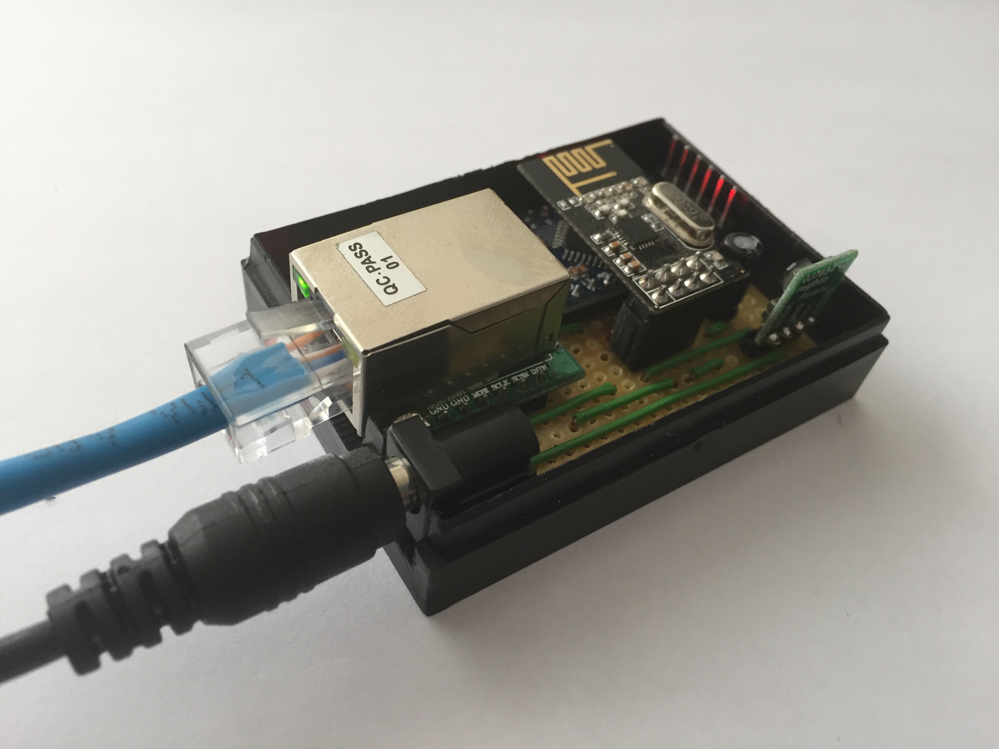
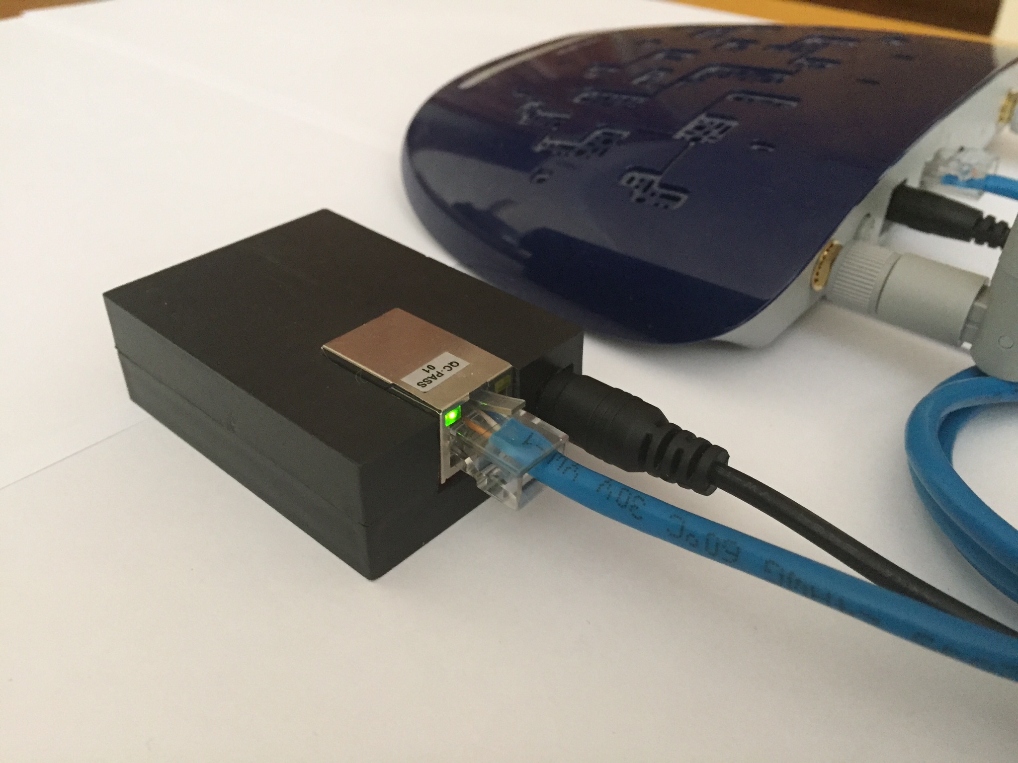
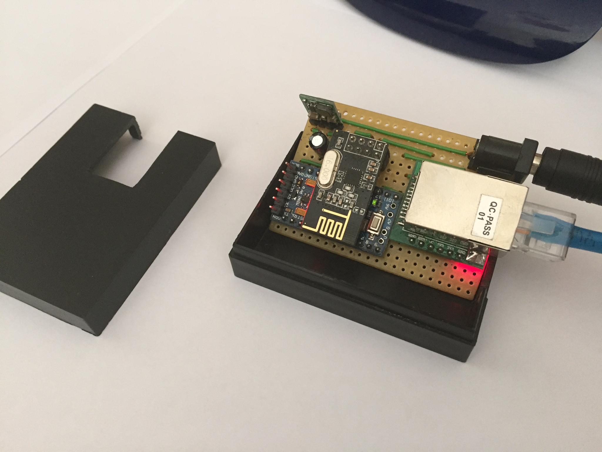
    I have it running with an MQTT broker, MQTT Gateway and some sensors. In fact, it’s running in parallel with a Domoticz Controller, both registering the same data from my sensors, installed on the same Raspberry.

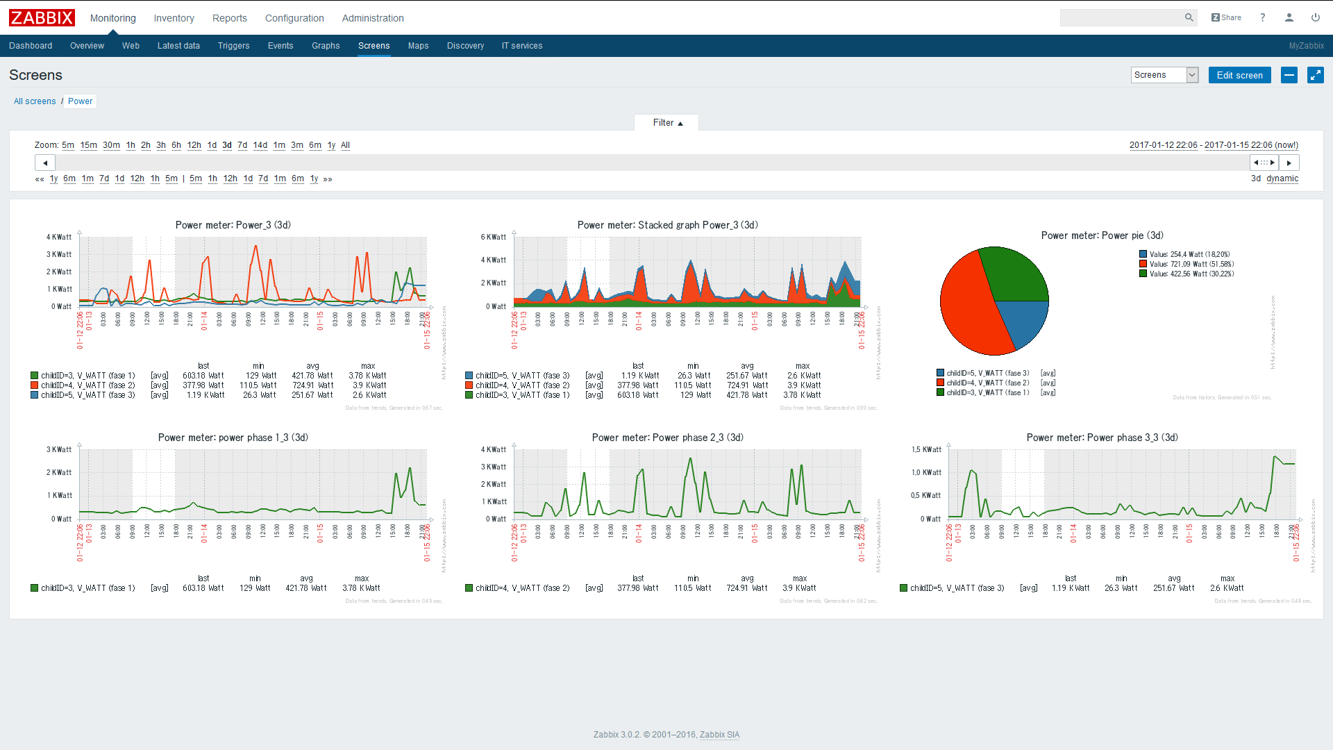
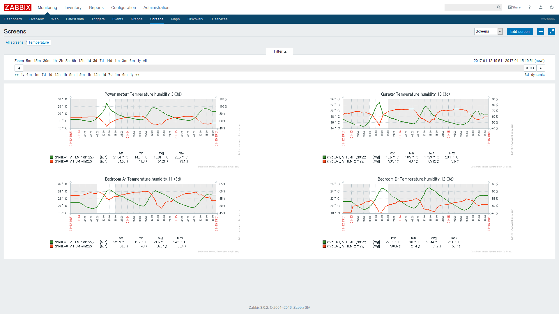
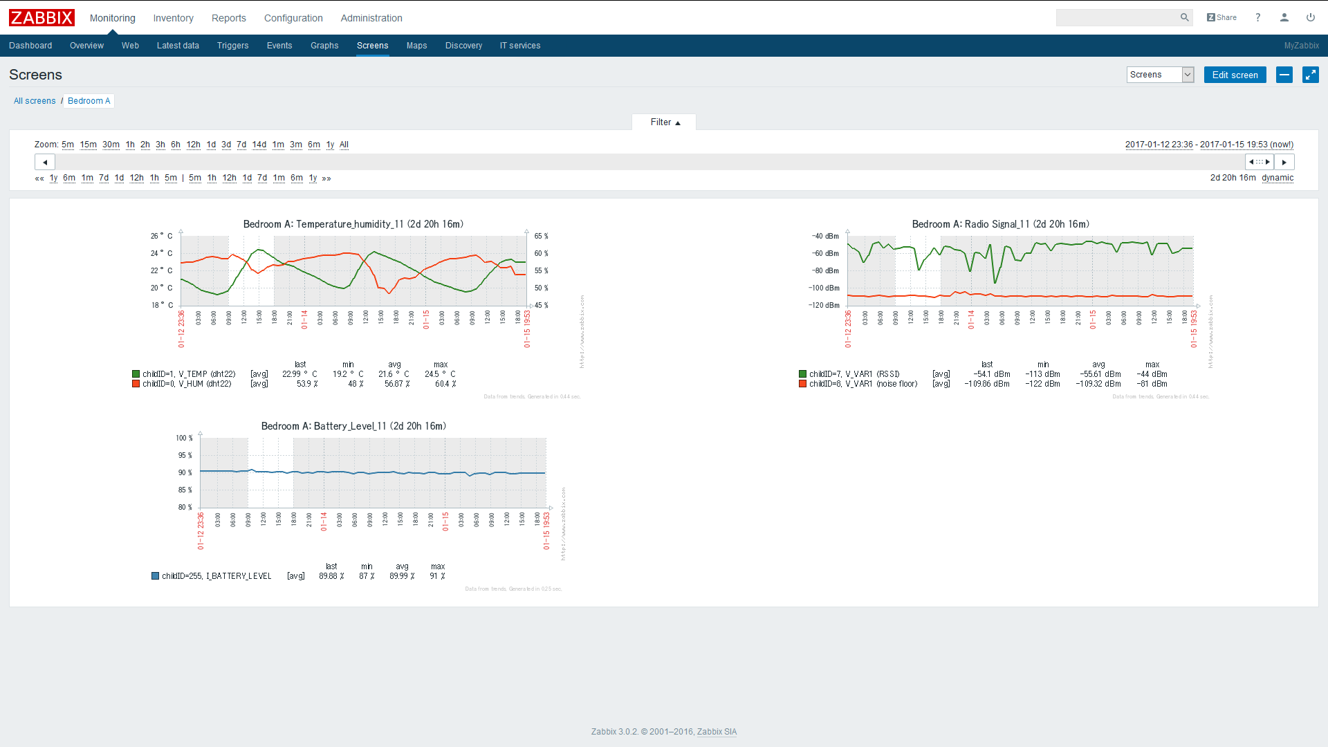
    • Here are a couple of screens from my setup, showing temperature and energy sensors in operation.

    0_1484536092844_zabbix power_2.png
    0_1484528051690_zabbix temperature.png
    0_1484528092916_zabbix dht22.png

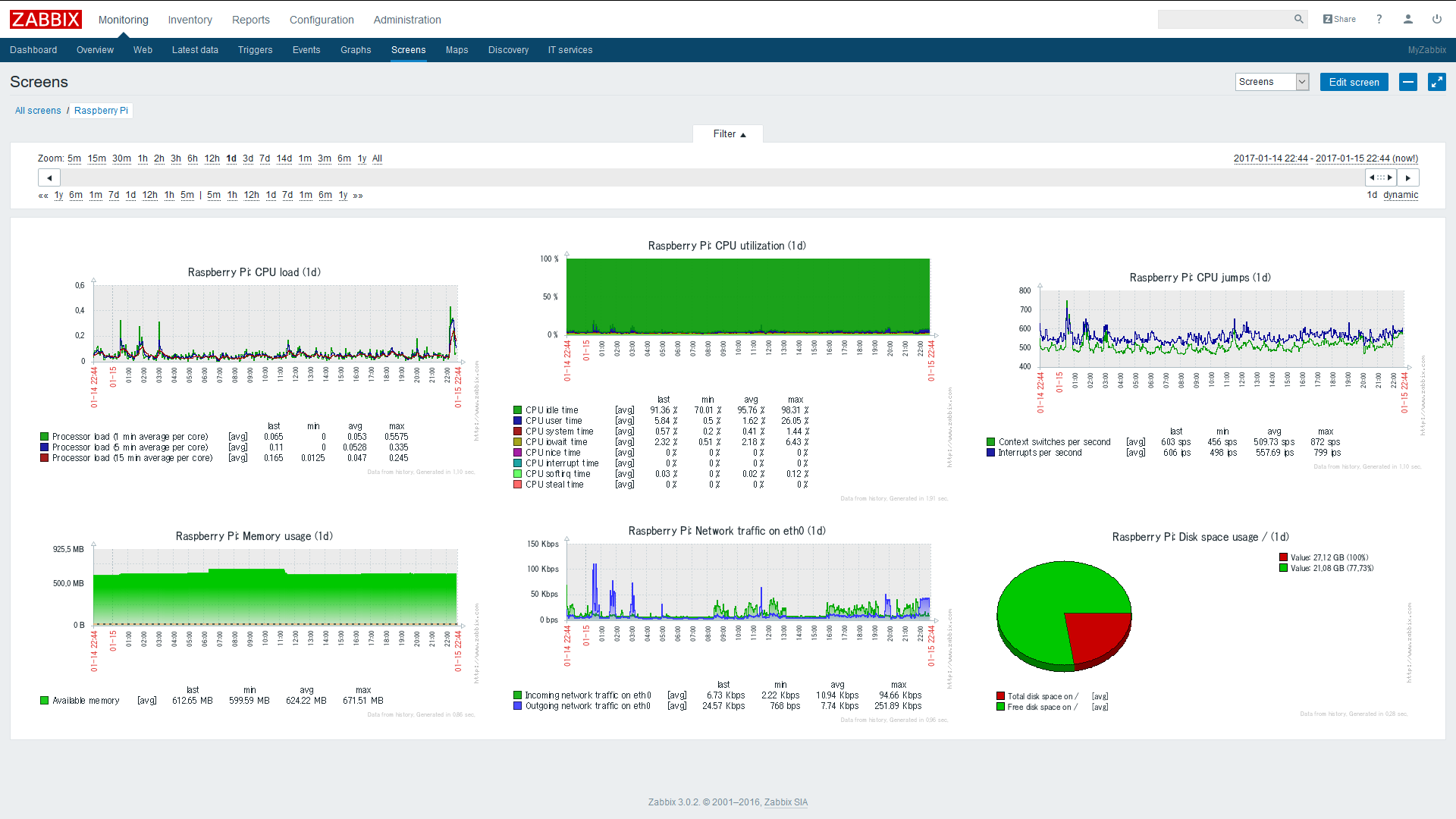
    • Zabbix comes with a Plug and Play Linux Servers monitoring setup via preinstalled templates, like the Raspberry Pi. It sends alerts automatically if there’s some issue. Here's a screen example from my setup.

    0_1484538364986_zabbix Linux_2.png

    1. Setup procedure. MQTT Broker

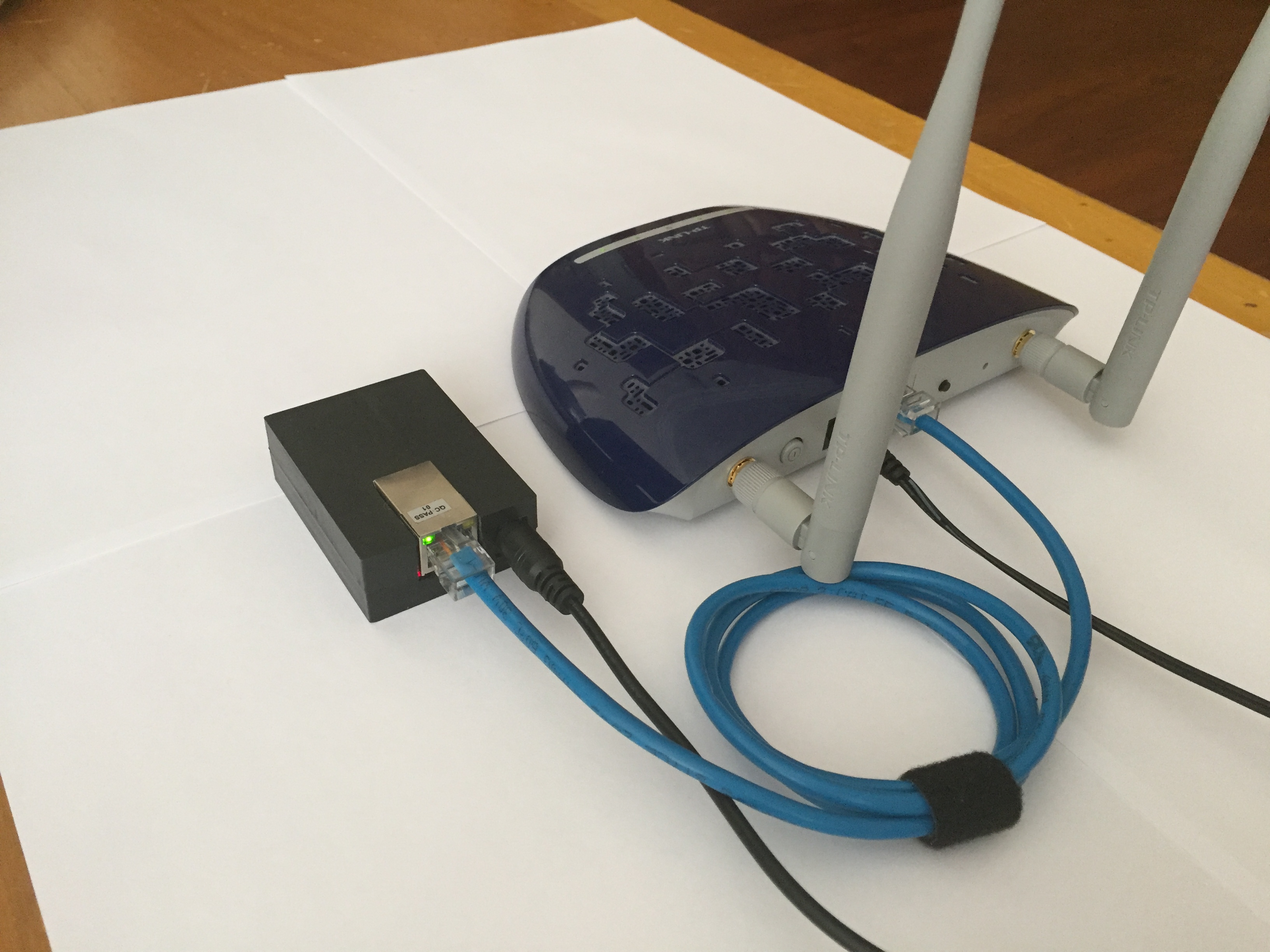
    First the Raspberry needs to have an MQTT broker running to capture and distribute MQTT messages, from a MySensors MQTT gateway client in this case. Mosquitto I guess is the best choice.
    Follow the instructions on this page to install the MQTT Mosquitto Broker:
    http://www.instructables.com/id/Installing-MQTT-BrokerMosquitto-on-Raspberry-Pi/
    Or run directly with the following commands on your Raspberry Pi:

    sudo apt-get update
    sudo apt-get install mosquitto
    sudo apt-get install mosquitto-clients
    
    1. Instructions on how to install zabbix on the Raspberry Pi, using MySQL as database

    Zabbix needs a database to run. MySQL is selected as database in this setup.
    There are two packages needed from Zabbix to get it working. zabbix-server-mysql and zabbix-frontend-php. As well it’s recommended you install zabbix-agent on the Raspberry. Zabbix can then monitor the Raspberry Pi performance automatically through the zabbix-agent tpgether with pre-installed templates.
    If you install Zabbix directly via "apt-get install" the version you get is rather old (zabbix 2.x), and I got into some trouble trying to get it to work. The web page further down did work straight forward in my case. It installs zabbix v3.0. Have a look at the zabbix 3.0 manual: https://www.zabbix.com/documentation/3.0/manual

    If you don't have mysql installed. Do this first on the Raspberry:

    sudo apt-get install mysql-server mysql-client
    
    1. Installing zabbix 3.0

    Follow the page, step by step, to install Zabbix on your Raspberry Pi. It installs the version zabbix 3.0:

    http://devopsish.blogspot.com/2016/05/installing-zabbix-3-on-raspberry-pi.html

    You should now have got installed

    • zabbix-server-mysql

    • zabbix-frontend-php

    • zabbix-agent

    on your Raspberry Pi. You can now access Zabbix from a web browser pointing at the Raspberry IP address. Eg. http://192.168.1.70/zabbix

    • You should get to the login screen.

    0_1484528956759_zabbix Login.png
    Enter with User = Admin, Password = zabbix. Later on you can add and modify other users for access control.

    1. Setup zabbix-sender

    Additionally we’ll need to install the package zabbix-sender to be able to send the MQTT messages from a script to the Zabbix Server.
    On your Raspberry Pi enter:

    cd ~
    cd zabbix3-rpi-master
    sudo dpkg –i zabbix-sender_3.0.*-1+jessie_armhf.deb
    
    1. Zabbix setup concepts

    To pass MQTT messages from the MQTT broker to Zabbix I wrote a small Python script. Please note, the MQTT format with MySensors is "topic/a/b/c/d/e", but Zabbix doesn't allow the letter "/" in an “item key”, it's therefore changed in the Python script to the format "topic.a.b.c.d.e".
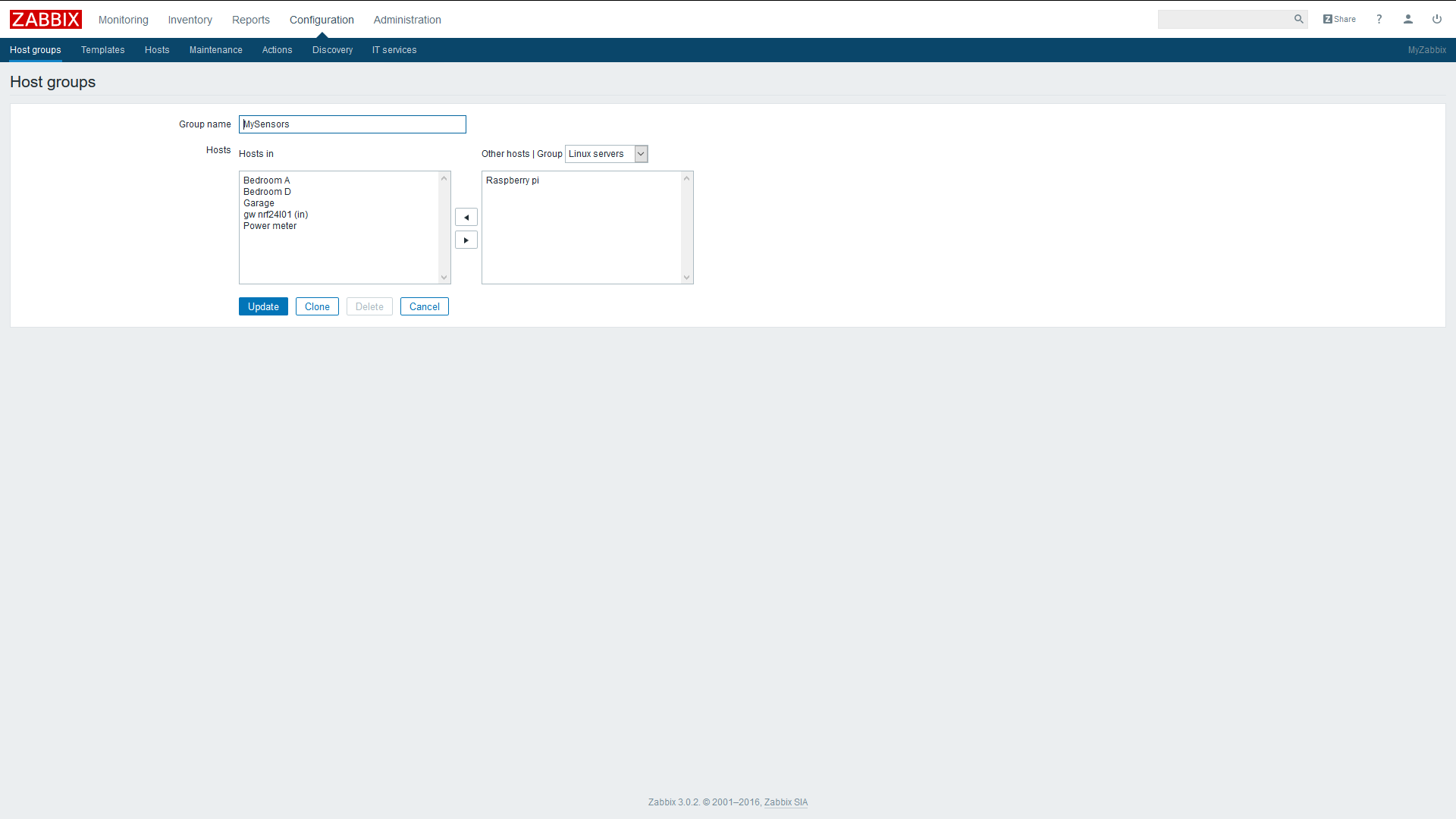
    In Zabbix I have setup a hostgroup named “MySensors”. Added to the hostgroup are the sensor nodes (hosts). To the hosts are added the sensor children (items) following the MySensors MQTT format:

    MY_MQTT_TOPIC_PREFIX/SENSOR-NODE-ID/SENSOR-CHILD-ID/CMD-TYPE/ACK-FLAG/SUB-TYPE

    • hostgroup = "MySensors”

    • host = MY_MQTT_TOPIC_PREFIX + "." + MY_NODE_ID
      eg. mygateway1-out.5

    • item = CHILD_ID + "." + CMD-TYPE + "." + "ACK-FLAG" + "." + SUB-TYPE
      eg. 1.1.0.0 (Child Id = 1, Cmdtype = set, Ack = 0, Subtype = V_TEMP)

    The Zabbix items should be set to the type “zabbix trapper”. You find the items at -configuration-, -host-, -item-. Zabbix trapper listens to messages sent from “zabbix-sender”, which we’re going to use here.
    Be aware. No automatic node assignment to the Sensor Nodes from the Controller would work with Zabbix in this setup.
    So we need to preset the Node_ID in the MySensor arduino scripts e.g.:

    #define MY_NODE_ID   1
    
    1. Zabbix setup
    • Define a hostgroup and give it a name.

    0_1484529453507_zabbix hostgroup.png

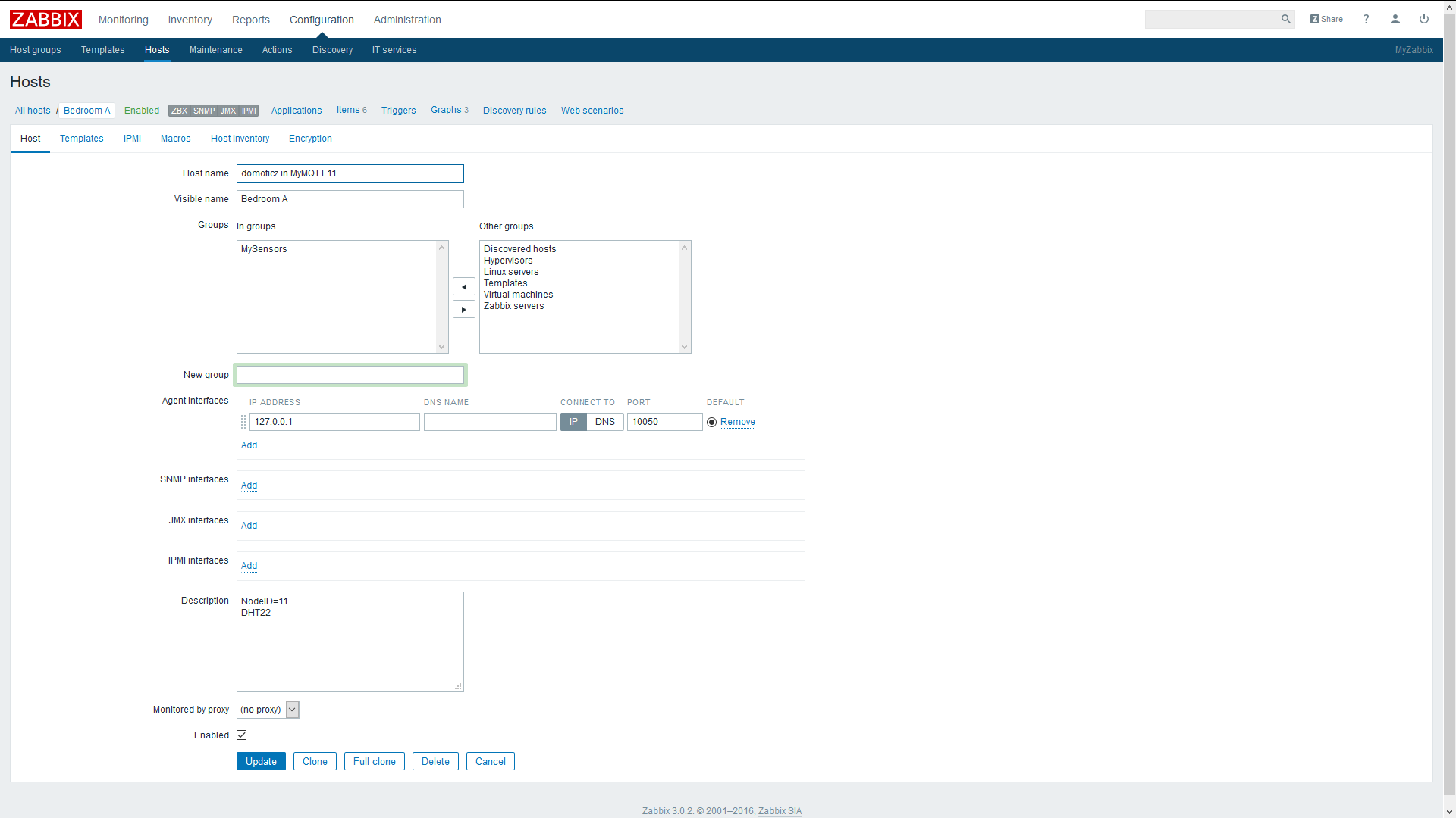
    • Define some hosts (sensor nodes). The host name must have an exact match with your mqtt gateway topic name and node id separated with a dot (MY_MQTT_TOPIC_PREFIX + "." + MY_NODE_ID)
      In this example I'm using “domoticz.in.MyMQTT.11” with the node = 11.

    0_1484529557434_zabbix host.png

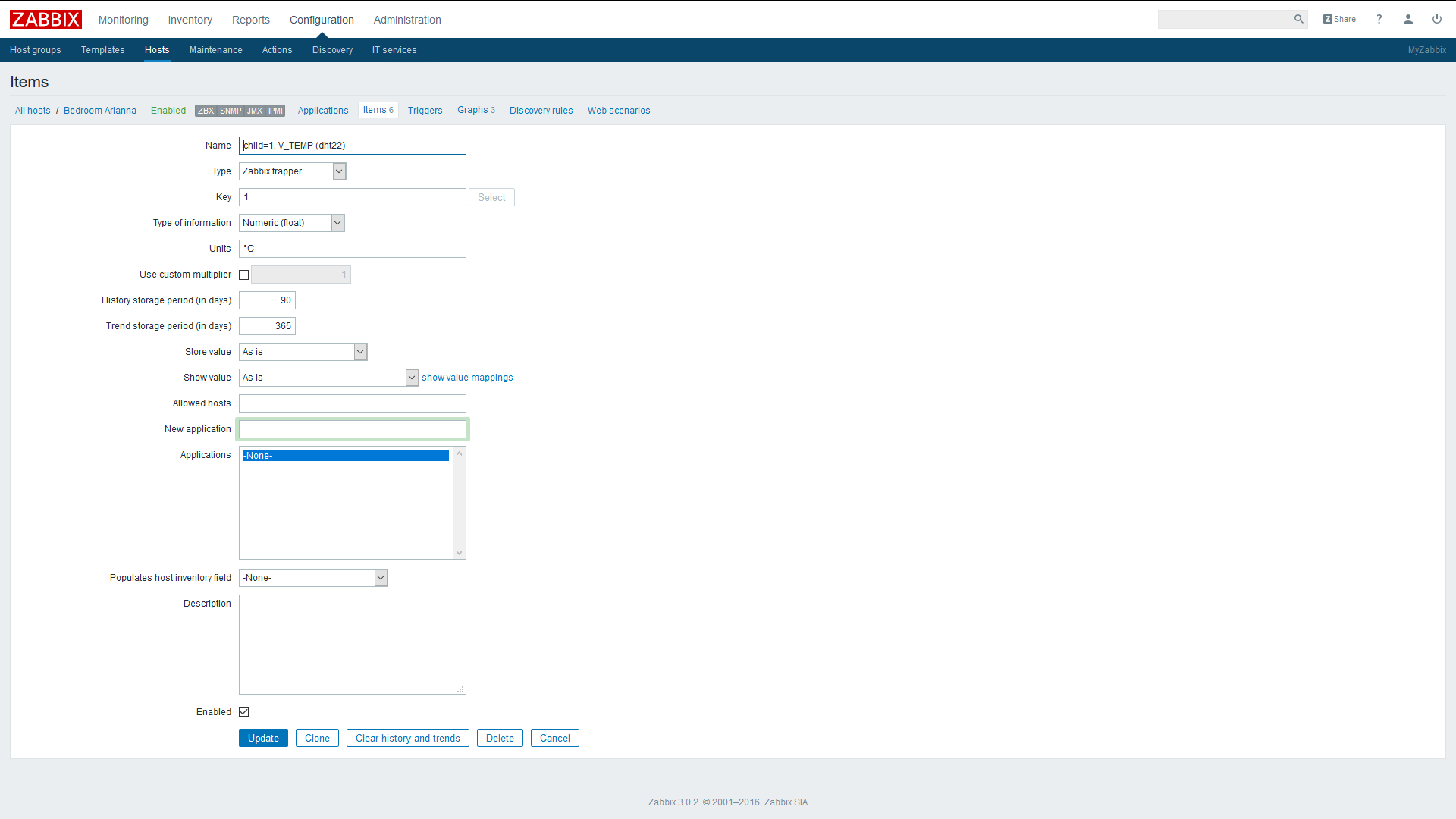
    • Define some items (children) to your sensor nodes
      Give them a name of your choice. Select Type = Zabbix trapper. The key for each item is the Child-Id taken from the MySensors MQTT message. In this case Child-ID = 1.

    Note: edited 2017-01.22. Key for items has been modified to only use Child-id, to fit integration of Auto-Discovery. See part 2.

    0_1485145829823_zabbix item.png

    1. Zabbix-sender

    There is an executable that’s now available “zabbix_sender” that you can use to test directly from the command line in the Raspberry. Try sending to an item that’s been previously setup in Zabbix by executing the command:

    zabbix_sender -v -z localhost -s domoticz.in.MyMQTT.11 -k 1 -o 10.5
    

    A response should look something like:

    info from server: "processed: 1; failed: 0; total: 1; seconds spent: 0.000176"
    sent: 1; skipped: 0; total: 1
    

    If failed = 0, sent = 1 everything should be ok in the setup.

    You should now see the message show up in Zabbix. Look it up in Zabbix, in “Monitoring” and select “Latest Data”. You should see an event with temperature 10.5 °C registered in the node = 11, Child = 1. That is, hostname = “domoticz.in.MyMQTT.11” with key item = “1” and with the payload = 10.5 received.

    Note: edited 2017-01-22. Key format modified to key=child-id to fit Auto-Discovery. Check on part 2.

    1. Python script

    The Python script uses two libraries that we have to download first:
    Mosquito client library. See: www.mosquitto.org and https://pypi.python.org/pypi/paho-mqtt

    pip install paho-mqtt
    

    Library that uses zabbix-sender / zabbix-api See: https://www.zabbix.org/wiki/Docs/api/libraries
    And: https://github.com/blacked/py-zabbix

    pip install py-zabbix
    

    Prepare a script named e.g. “mqtt_zabbix.py”, with your favorite editor, like vi or nano.

    nano mqtt_zabbix.py
    

    Paste the Python script below and save the file. Run for example the script in the background, as a daemon, from the command line. The script stores the stdout and stderr printouts in the text file “zabbix.log”:

    python -u mqtt_zabbix.py > zabbix.log 2>&1 &
    

    The file zabbix.log stores the sent MQTT events, with a time stamp and the result received from zabbix-sender. Useful for debugging.

    Python script:

    import paho.mqtt.client as mqtt
    import time
    from  pyzabbix import ZabbixMetric, ZabbixSender
    
    topic_sub = "domoticz/in/MyMQTT/"
    
    # The callback for when the client receives a CONNACK response from the server.
    def on_connect(client, userdata, flags, rc):
        print("Connected with result code "+str(rc))
    
        # Subscribing in on_connect() means that if we lose the connection and
        # reconnect then subscriptions will be renewed.
        client.subscribe(topic_sub+"+/+/+/+/+")
    
    # The callback for when a PUBLISH message is received from the server.
    def on_message(client, userdata, msg):
        msg.topic = msg.topic.replace("/", ".")
    
        myNode = msg.topic[:msg.topic.find(".", len(topic_sub)+1)]
        myItem = msg.topic[len(myNode)+1:]
        mySplit = myItem.split('.')  # split topic to indexed list
    
        if mySplit[1] == '1':        # type = set
            myItem = mySplit[0]      # change item to child-id
    
        metrics = [ZabbixMetric(myNode, myItem, msg.payload)]
        result = ZabbixSender(use_config=True).send(metrics)
    
        print(time.strftime("%c")+" "+str(result)+" : "+myNode+" "+myItem+" "+str(msg.payload))
    
    
    client = mqtt.Client()
    client.on_connect = on_connect
    client.on_message = on_message
    
    client.connect("localhost", 1883, 60)


    In the script, to change the MQTT format from topic/a/b/c/d/e to topic.a.b.c.d.e, required by zabbix, this Python line fixes it:

        msg.topic = msg.topic.replace("/", ".")
    

    These two lines make the deal to send the MQTT events to Zabbix:

        metrics = [ZabbixMetric(myNode, myItem, msg.payload)]
        result = ZabbixSender(use_config=True).send(metrics)
    

    It’s possible to add triggers to the items in Zabbix, to generate alerts from MQTT sensor events received. Alerts can as well be sent by e.g. SMS, Email or script (outside this scope).

    My next steps will be to create sensor nodes automatically (hosts) and it’s children (items), by preparing some Templates in Zabbix together with zabbix.api or zabbix LLD. And as well have a look into how to send messages from Zabbix to MySensor relays and actuators, and for autonomous flow actions.

    Enjoy and have fun!

    Controllers

  • Domoticz now supports the MySensors MQTT Gateway
    J jpaulin

    I just wanted to share my latest discovery. Domoticz now supports the MySensors MQTT Gateway.
    A push was made by Rogier Reedijk, xs4free in November. Thanks Rogier, really great stuff! This was the main reason why I personally didn´t use Domoticz before as a controller. For the moment it's only available as Beta version.
    Pls. have a look at the Domoticz Wiki page, showing how to setup the MySensors MQTT GW in the Domoticz environment.

    Domoticz

  • [solved] RFM69 based nodes unable to report Lib Version
    J jpaulin

    @korttoma Sharing a pair of photos of my gw. Became pretty neat, I think. It's parked permanently beside the WiFi Router.
    0_1478804847890_IMG_5989.JPG

    0_1478804919975_IMG_6002.JPG

    Bug Reports

  • RFM69 RSSI value report
    J jpaulin

    @rmtucker Here's the complete sketch. It's a DHT22 temp/humidity battery powered sensor node with an RFM69 radio.

    /**
     * The MySensors Arduino library handles the wireless radio link and protocol
     * between your home built sensors/actuators and HA controller of choice.
     * The sensors forms a self healing radio network with optional repeaters. Each
     * repeater and gateway builds a routing tables in EEPROM which keeps track of the
     * network topology allowing messages to be routed to nodes.
     *
     * Created by Henrik Ekblad <henrik.ekblad@mysensors.org>
     * Copyright (C) 2013-2015 Sensnology AB
     * Full contributor list: https://github.com/mysensors/Arduino/graphs/contributors
     *
     * Documentation: http://www.mysensors.org
     * Support Forum: http://forum.mysensors.org
     *
     * This program is free software; you can redistribute it and/or
     * modify it under the terms of the GNU General Public License
     * version 2 as published by the Free Software Foundation.
     *
     *******************************
     *
     * REVISION HISTORY
     * Version 1.0 - Henrik EKblad
     * 
     * DESCRIPTION
     * This sketch provides an example how to implement a humidity/temperature
     * sensor using DHT11/DHT-22 
     * http://www.mysensors.org/build/humidity
     */
    
    // Enable debug prints
    #define MY_DEBUG
    
    // Enable and select radio type attached
    //#define MY_RADIO_NRF24
    #define MY_RADIO_RFM69
    
    #define MY_RFM69_FREQUENCY   RF69_433MHZ
    
    #define MY_NODE_ID 13                        // Identity for temp/hum sensor
    
    // Set blinking period
    #define MY_DEFAULT_LED_BLINK_PERIOD 50
    
    // Flash leds on rx/tx/err
    //#define MY_DEFAULT_ERR_LED_PIN 7           // Error led pin  red
    //#define MY_DEFAULT_RX_LED_PIN  6           // Receive led pin  yellow
    #define MY_DEFAULT_TX_LED_PIN  9             // Transmit led pin  green
    
    #define MY_WITH_LEDS_BLINKING_INVERSE
    
    const byte BATT_ADC = 1;                     // ADC Pin to measure battery level
    
    #include <MySensors.h>
    #include <DHT.h>
    
    
    unsigned long SLEEP_TIME = 300000;           // Sleep time between reads (in milliseconds)


    #define CHILD_ID_HUM 0
    #define CHILD_ID_TEMP 1
    #define DHTPIN 18                            // Input pin from DHT22
    #define DHT22_PWR 6                          // Vdc pin DHT22 to get it to sleep
    #define DHTTYPE DHT22
    
    DHT dht(DHTPIN, DHTTYPE);
    
    
    #define CHILD_ID_RSSI_HIGH  7                // RSSI received signal level
    #define CHILD_ID_RSSI_LOW   8                // RSSI background noise level
    #define CHILD_ID_TEMP2      9                // internal temperature RFM69 chip
    
    int rssi;                                    // RSSI RFM69 chip
    int temp2;                                   // Internal temperature RFM69 chip
    
    int batteryLevel;                            // measured battery level
    int batteryPcnt;                             // measured battery level in percentage
    
    MyMessage msgHum(CHILD_ID_HUM, V_HUM);
    MyMessage msgTemp(CHILD_ID_TEMP, V_TEMP);
    
    MyMessage msgRSSI1(CHILD_ID_RSSI_HIGH, V_VAR1);
    MyMessage msgRSSI2(CHILD_ID_RSSI_LOW, V_VAR1);
    MyMessage msgTemp2(CHILD_ID_TEMP2, V_TEMP);
    
    
    void setup()  
    { 
      pinMode(DHT22_PWR,OUTPUT);
      digitalWrite(DHT22_PWR,HIGH);              // power-on dht22
      wait(2000);
    
      dht.begin();                               // Start-up DHT22 sensor Temperature/Humidity
    }
    
    void presentation() 
    {
      // Send the sketch version information to the gateway and Controller
      sendSketchInfo("Temp_Hum", "1.0");
    
      // Register all sensors to gw (they will be created as child devices)
      present(CHILD_ID_HUM, S_HUM);
      present(CHILD_ID_TEMP, S_TEMP);
    
      present(CHILD_ID_RSSI_HIGH, S_CUSTOM);
      present(CHILD_ID_RSSI_LOW, S_CUSTOM);
      present(CHILD_ID_TEMP2, S_TEMP);
    }
    
    void loop()      
    {
      float humidity = dht.readHumidity();       // get dht22 humidity
      if (isnan(humidity)) {
        Serial.println("Failed reading humidity from DHT");
      } else {
        send(msgHum.set(humidity, 1));           // send dht22 humidity
        wait(200);
      }
    
      float temperature = dht.readTemperature(); // get dht22 temperature
      if (isnan(temperature)) {
        Serial.println("Failed reading temperature from DHT");
      } else {
        send(msgTemp.set(temperature, 1));       // send dht22 temperature
      }
      digitalWrite(DHT22_PWR,LOW);               // save some power
      
      rssi = _radio.readRSSI();                  // read RSSI in RFM69. Measure reception signal from gw
      send(msgRSSI1.set(rssi));                  // send RSSI level
      wait(500);                                 // wait to get idle
      
      rssi = _radio.readRSSI();                  // read RSSI in RFM69. Wait and measure background noise
      send(msgRSSI2.set(rssi));                  // send RSSI level
      wait(200);                                 // wait for next send
      
      temp2 = _radio.readTemperature(1);         // read temperature in RFM69
      send(msgTemp2.set(temp2));                 // send temperature
    
      batteryLevel = analogRead(BATT_ADC);       //  (* 0.0032225806)
      batteryPcnt = batteryLevel / 10;           // battery percentage
      
      sendBatteryLevel(batteryPcnt);             // send battery level in percentage to controller
    
      // if (oldBatteryPcnt != batteryPcnt) {    // use if not to send every cycle
      //     sendBatteryLevel(batteryPcnt);
      //     oldBatteryPcnt = batteryPcnt;
      // }
    
      
      sleep(SLEEP_TIME);                         // sleep a bit
      digitalWrite(DHT22_PWR,HIGH);              // wake up DHT sensor
      wait(2000);                                // warm up DHT sensor
    }
    
    void receive(const MyMessage &message) {
      // We only expect one type of message from controller. But we better check anyway.
      Serial.println("something came in");
      
      if (message.type==V_VAR1) {                // reception to change SLEEP_TIME.
         SLEEP_TIME = message.getULong();        // send topic: eg. my_RFM69_gw1-in/3/1/1/0/24 30000 (payload in ms)
       }                                         // MQTT_publish_topic_prefix/Node_Id/Sensor_Id/Cmd_Type/Ack_flag/type(V_VAR1=24) payload
    }


    readRSSI(); is an internal function in the RFM69.h / RFM69.cpp library that I'm calling in the sketch to get the RSSI and background noise level.

    Feature Requests

  • Instructions how-to use Zabbix as your Controller with MQTT, part 2 (Auto-Discovery of Sensors)
    J jpaulin

    Part 2. First have a look at part 1.

    Here's an additional script created in Python to implement Auto-Discovery and automatic creation of sensors and nodes in Zabbix. It's using the Zabbix-API to check and create hostgroup, hosts and items automatically, if they're new and presented to the Controller (after power-on of the node sensors). The script runs on my RPI, where my Mosquitto and Zabbix is installed too.

    Script description.
    The script connects to the mosquitto broker and listens to the MQTT traffic from the MySensors network.

    1. First it checks if the Zabbix-hostgroup exists, named "MySensors". If not it's created automatically.
    2. When a new sensor-node is presented via MQTT a Zabbix-host is created automatically, added to the hostgroup, and the host is named with the Topics prefix + Node-ID.
    3. When a new Child sensor is presented a Zabbix-Item is created, added to the host, and given the name of the Presentation Topic. The key of the Zabbix-Item is set to the value of Child-Id. The Item-name can later be modified to anything of your preference.

    Run the script in the background together with the script described in part 1. The first script passes the data to Zabbix. And this script handles the automatic creation of the sensors.

    Script:

    import paho.mqtt.client as mqtt
    import time
    from  pyzabbix import ZabbixMetric, ZabbixSender
    from zabbix.api import ZabbixAPI
    
    
    # Create ZabbixAPI class instance
    zapi = ZabbixAPI(url='http://localhost/zabbix/', user='Admin', password='zabbix')
    
    # Moquitto Topic Prefix
    topic_sub = "domoticz/in/MyMQTT/"
    
    # Name of Zabbix hostgroup
    hostGroup = 'MySensors'
    
    # Create hostgroup, if missing
    result = zapi.do_request('hostgroup.get', {'filter': {'name': [hostGroup]}})
    if [name['name'] for name in result['result']] == []:
         zapi.hostgroup.create(name=hostGroup)
         result = zapi.do_request('hostgroup.get', {'filter': {'name': [hostGroup]}})
         print(time.strftime("%c")+" Hostgroup created: "+hostGroup+" : "+str(result))      # log hostgroup creation
    
    # Get hostgroup-id
    groupId = [name['groupid'] for name in result['result']]
    
    
    # Mosquitto: the callback for when the client receives a CONNACK response from the server.
    def on_connect(client, userdata, flags, rc):
        print("Connected with result code "+str(rc))
    
        # Mosquitto: subscribing in on_connect() means that if we lose the connection and
        # reconnect then subscriptions will be renewed.
        client.subscribe(topic_sub+"+/+/+/+/+")
    
    # Mosquitto: the callback for when a PUBLISH message is received from the server.
    def on_message(client, userdata, msg):
        msg.topic = msg.topic.replace("/", ".")
    
        myNode  = msg.topic[:msg.topic.find(".", len(topic_sub)+1)]
        myItem  = msg.topic[len(myNode)+1:]
        mySplit = myItem.split('.')
    
    
        # Check if host (node) exist, or create new host.
        # 255 = child, 0 = presentation, 17 = S_ARDUINO_NODE
        if myItem == '255.0.0.17':
            result = zapi.do_request('host.get', {'filter':{'host':[myNode]}})
            if [host['host'] for host in result['result']] == []:                           # new node sensor, create host
                result = zapi.do_request('host.create', {'host': myNode, 'interfaces': [{'type': 1, 'main': 1, 'useip': 1, 'ip': '127.0.0
    .1', 'dns': '', 'port': '10050'}], 'groups': [{'groupid': groupId[0]}]})
                print(time.strftime("%c")+" Host created: "+myNode+" : "+str(result))       # log host creation
    
                # create item I_BATTERY_LEVEL
                result = zapi.do_request('host.get', {'filter':{'host':[myNode]}})
                hostId = [item['hostid'] for item in result['result']]
                result = zapi.do_request('item.create', {'hostid': hostId[0], 'value_type': '0','type': '2', 'name': 'I_BATTERY_LEVEL', '
    key_': '255.3.0.0'})
                print(time.strftime("%c")+" Item created: I_BATTERY_LEVEL : "+str(result))  # log item creation
    
        if mySplit[1] == '0':        # command = presentation
            if mySplit[0] != '255':  # child = 255, don't create item
                result = zapi.do_request('item.get', {'host': myNode, 'filter': {'key_':[mySplit[0]]}})
                if [host['key_'] for host in result['result']] == []:                       # new child, create item
                    result = zapi.do_request('host.get', {'filter':{'host':[myNode]}})
                    hostId = [item['hostid'] for item in result['result']]
                    result = zapi.do_request('item.create', {'hostid': hostId[0], 'value_type': '0','type': '2', 'name': myItem, 'key_':
    mySplit[0]})
                    print(time.strftime("%c")+" Item created: "+myItem+" : "+str(result))   # log item creation


    # Mosquitto: client start-up.
    client = mqtt.Client()
    client.on_connect = on_connect
    client.on_message = on_message
    
    client.connect("localhost", 1883, 60)
    
    
    # Mosquitto: blocking call that processes network traffic, dispatches callbacks and
    # handles reconnecting.
    client.loop_forever()


    Run the script e.g. in the background as a daemon and printouts sent to a log file "zabbix_cnfg.log

    python -u mqtt_zabbix_api.py > zabbix_cnfg.log 2>&1 &
    

    I'm quite new with Python scripting, so it's possible the code isn't that elegant. But it works fine for me. :simple_smile:
    And it's fun! :smile:

    Controllers

  • LEDs on GW and nodes aren't working as expected
    J jpaulin

    The LEDs, both om my GWs and on my nodes, aren't working as expected. I'm using ATmega328, RFM69W, MQTT Ethernet on the GW and an updated version from the development branch.
    Making some traces in the code of MyLeds.cpp it looks like the variable "prevTime" isn't being updated correctly.
    In the routine "ledsProcess()" the variable "prevTime" is expected to be udated when timeout occurs comparing it with hwMillis(); and prepare itself for the next timeout to update the LEDs. But the variable is getting out of track and the LEDs get stuck for moments or aren't flickering when they should.

    Making the following change solves it.
    Change line: https://github.com/mysensors/MySensors/blob/development/core/MyLeds.cpp#L58

    prevTime += LED_PROCESS_INTERVAL_MS;
    

    to:

    prevTime = hhMillis();
    

    Maybe @hek or @tbowmo could look into this and verify if' it's the preferred solution or perhaps propose a better one.
    If you need some more detailed traces from my rig, pls. let me know.:smiley:

    Bug Reports

  • RFM69 RSSI value report
    J jpaulin

    @rmtucker In my RFM69 sensors using ver2.1 I'm doing as follows to check RSSI and, as well, how to check the background noise level. I have them implemented as two sensor values being reported every 5 minutes in the loop() to the gateway and controller.

    void loop()      
    {
      float humidity = dht.readHumidity();       // get dht22 humidity
      if (isnan(humidity)) {
        Serial.println("Failed reading humidity from DHT");
      } else {
        send(msgHum.set(humidity, 1));           // send dht22 humidity
      }
    
      float temperature = dht.readTemperature(); // get dht22 temperature
      if (isnan(temperature)) {
        Serial.println("Failed reading temperature from DHT");
      } else {
        send(msgTemp.set(temperature, 1));       // send dht22 temperature
      }
      digitalWrite(DHT22_PWR,LOW);               // save some power. Turn off dht22 module.
      
      rssi = _radio.readRSSI();                  // read RSSI in RFM69. Measure reception signal level from gw
      send(msgRSSI1.set(rssi));                  // send RSSI, signal level to gateway
    
      wait(500);                                 // wait to get idle
      rssi = _radio.readRSSI();                  // read RSSI in RFM69. Measure background noise
      send(msgRSSI2.set(rssi));                  // send RSSI, noise level to gateway
      
      sleep(SLEEP_TIME);                         // sleep a bit
      digitalWrite(DHT22_PWR,HIGH);              // wake up dht22 module
      wait(2000);                                // warm up dht22 module
    }
    

    To get the RSSI value it's read in the sketch ( int rssi = _radio.readRSSI(); ) immediately after sending something, in this case the dht22 temperature. To check the background noise the RSSI level is read again 500ms after being kept idle (probably a shorter waiting period would work as well, but haven't studied it as it's not a critical issue for me). Normally the background noise-floor should be something around -95dBm and -115dBm. If you have some external interference, it could be easily detected with this method.

    Feature Requests

  • [solved] RFM69 based nodes unable to report Lib Version
    J jpaulin

    @korttoma
    My RFM69 - Ethernet - GW has the following setup.

    On the RFM69 radio I'm using D10 as CS pin (Chip Select). This is because in my case the RFM69 radio is hard-wired to pin D10, as with eg. a Moteino or Anarduino. But this is not mandatory. If you use an Arduino Pro Mini you could select another pin for the RFM69 CS-pin on the Arduino, if you want.

    The Ethernet W5100 uses the Arduino IDE pre-installed library Ethernet.h. In the library the CS-pin is as well fixed to D10. CS of course has to be unique for each SPI slave device. I changed directly in the Ethenet.h library the CS pin to be D7. But D9, D8 or some other pin is ok to use as well.

    Take care, if none of your SPI Slave devices (radio and W5100) uses D10 as CS-pin. In this case make sure to set the D10 pin to OUTPUT in your sketch to keep the Arduino as SPI Master. On the ATmega328 the D10 pin is hard-wired to be the SS pin (Slave Select). The Arduino has to always be the SPI Master and the devices SPI Slaves on the SPI bus to get everything to work.

    Another consideration is:
    The RFM69 radio uses the SPI functions during the interrupt sequence (Pin D2). The Ethernet.h library won't work correctly if another device uses SPI signalling during an interrupt sequence. The fix I'm using is to block interrupts from the radio-unit during SPI usage of the W5100 unit. I haven't seen any flaws with this fix so far. I've found other people on the internet using the same fix too without issues.

    To use RFM69 CS=D10 pin and W5100 CS=D9 pin do the following change in the W5100.h that is part of the Ethernet library.
    If you use a Windows computer you'll find the file here:

    C:\Program Files (x86)\Arduino\libraries\Ethernet\src\utility\w5100.h

    Look for the following lines at the end of the file.

    #else
      inline static void initSS()    { DDRB  |=  _BV(2); };
      inline static void setSS()     { PORTB &= ~_BV(2); };
      inline static void resetSS()   { PORTB |=  _BV(2); };
    #endif
    

    If you use D9 as CS pin for the W5100 module change as follows:

    #else
      inline static void initSS()    { DDRB  |=  _BV(1); };
      inline static void setSS()     { cli(); PORTB &= ~_BV(1); };
      inline static void resetSS()   { PORTB |=  _BV(1); sei(); };
    #endif
    

    If you uses, as I do, D7 as CS pin then change as follows:

    #else
      inline static void initSS()    { DDRD  |=  _BV(7); };
      inline static void setSS()     { cli(); PORTD &= ~_BV(7); };
      inline static void resetSS()   { PORTD |=  _BV(7); sei(); };
    #endif
    

    If you want to keep D10 for the W5100 just add the cli(); and sei(); macros. (cli = clear interrupt. sei = set interrupt).

    If you want to use another SPI CS pin than D10 on the RFM69 radio (eg. D9) it should be safe to modify it directly in the sketch with the preprocessor constant:

    #define MY_RF69_SPI_CS 9
    

    For the MOSI, MISO and SCK pins use as mentioned above, they are as well hard-wired in the ATmega328 chip to D11,D12 and D13.

    If you have any doubts please let me know.

    Bug Reports

  • My Ethernet Gateway Board (W5500)
    J jpaulin

    @mtiutiu
    I'm using MY_SOFTSPI to separate the SPI ports. I've never tried to share the SPI-bus with an NRF24 radio and W5500.

    I've seen Adafruit has released a library named "Ethernet2.h" for the W5500 module. It's a nice alternative, no need to replace the library when switching between a W5100 and W5500 Ethernet module. Haven't tested it, though.

    For an RFM69 gateway that I've built with a W5500 Ethernet module I'm sharing the SPI bus. No SOFTSPI setup is available yet for the RFM69, as far as I know. In the following thread you can see my setup sharing the SPI port between an RFM69 radio and W5500 Ethernet module.
    I saw a major transport rework was released Mar 28 in the development branch with a lot of new stuff. Maybe some solution has been included to share the SPI port Out of the Box?

    Hardware

  • RFM69 RSSI value report
    J jpaulin

    @rmtucker Another feature I'm using in the sketch, by calling directly the RFM69 library, is reading the temperature sensor in the RFM69.

    temp2 = _radio.readTemperature(1);         // read temperature in RFM69
    

    The value (1) sent in the call above to the RFM69 library is a calibration in Centigrades (e.g. 1 = +1 °C). Added here to show the possibility to adjust the measured temperature. The temperature sensor on the chip is not as accurate as for example a dht22 and needs sometimes some manual adjustment.

    Feature Requests

  • Presentation of local sensor with GatewayESP8266MQTTClient seems to fail
    J jpaulin

    @hek
    Yes, that fixed the issue. Thanks. :smiley:

    Bug Reports

  • My Ethernet Gateway Board (W5500)
    J jpaulin

    @treborjm87
    Sorry. I missed your chat.
    Here's the code. I'm using the standard W5100 example with mqtt.

    /**
     * The MySensors Arduino library handles the wireless radio link and protocol
     * between your home built sensors/actuators and HA controller of choice.
     * The sensors forms a self healing radio network with optional repeaters. Each
     * repeater and gateway builds a routing tables in EEPROM which keeps track of the
     * network topology allowing messages to be routed to nodes.
     *
     * Created by Henrik Ekblad <henrik.ekblad@mysensors.org>
     * Copyright (C) 2013-2015 Sensnology AB
     * Full contributor list: https://github.com/mysensors/Arduino/graphs/contributors
     *
     * Documentation: http://www.mysensors.org
     * Support Forum: http://forum.mysensors.org
     *
     * This program is free software; you can redistribute it and/or
     * modify it under the terms of the GNU General Public License
     * version 2 as published by the Free Software Foundation.
     *
     *******************************
     *
     * REVISION HISTORY
     * Version 1.0 - Henrik Ekblad
     *
     * DESCRIPTION
     * The W5100 MQTT gateway sends radio network (or locally attached sensors) data to your MQTT broker.
     * The node also listens to MY_MQTT_TOPIC_PREFIX and sends out those messages to the radio network
     *
     * LED purposes:
     * - To use the feature, uncomment WITH_LEDS_BLINKING in MyConfig.h
     * - RX (green) - blink fast on radio message recieved. In inclusion mode will blink fast only on presentation recieved
     * - TX (yellow) - blink fast on radio message transmitted. In inclusion mode will blink slowly
     * - ERR (red) - fast blink on error during transmission error or recieve crc error
     *
     * See http://www.mysensors.org/build/esp8266_gateway for wiring instructions.
     * nRF24L01+  ESP8266
     * VCC        VCC
     * CE         GPIO4
     * CSN/CS     GPIO15
     * SCK        GPIO14
     * MISO       GPIO12
     * MOSI       GPIO13
     *
     * Not all ESP8266 modules have all pins available on their external interface.
     * This code has been tested on an ESP-12 module.
     * The ESP8266 requires a certain pin configuration to download code, and another one to run code:
     * - Connect REST (reset) via 10K pullup resistor to VCC, and via switch to GND ('reset switch')
     * - Connect GPIO15 via 10K pulldown resistor to GND
     * - Connect CH_PD via 10K resistor to VCC
     * - Connect GPIO2 via 10K resistor to VCC
     * - Connect GPIO0 via 10K resistor to VCC, and via switch to GND ('bootload switch')
     *
      * Inclusion mode button:
     * - Connect GPIO5 via switch to GND ('inclusion switch')
     *
     * Hardware SHA204 signing is currently not supported!
     *
     * Make sure to fill in your ssid and WiFi password below for ssid & pass.
     */
    
    
    // Enable debug prints to serial monitor
    #define MY_DEBUG
    
    // Enables and select radio type (if attached)
    #define MY_RADIO_NRF24
    //#define MY_RADIO_RFM69
    
    #define MY_GATEWAY_MQTT_CLIENT
    
    // Set this node's subscribe and publish topic prefix
    #define MY_MQTT_PUBLISH_TOPIC_PREFIX "mygateway1-out"
    #define MY_MQTT_SUBSCRIBE_TOPIC_PREFIX "mygateway1-in"
    
    // Set MQTT client id
    #define MY_MQTT_CLIENT_ID "mysensors-1"
    
    // W5100 Ethernet module SPI enable (optional if using a shield/module that manages SPI_EN signal)
    //#define MY_W5100_SPI_EN 4
    
    // Enable Soft SPI for NRF radio (note different radio wiring is required)
    // The W5100 ethernet module seems to have a hard time co-operate with
    // radio on the same spi bus.
    #if !defined(MY_W5100_SPI_EN) && !defined(ARDUINO_ARCH_SAMD)
      #define MY_SOFTSPI
      #define MY_SOFT_SPI_SCK_PIN 14
      #define MY_SOFT_SPI_MISO_PIN 16
      #define MY_SOFT_SPI_MOSI_PIN 15
    #endif
    
    // When W5100 is connected we have to move CE/CSN pins for NRF radio
    #ifndef MY_RF24_CE_PIN
      #define MY_RF24_CE_PIN 5
    #endif
    #ifndef MY_RF24_CS_PIN
      #define MY_RF24_CS_PIN 6
    #endif
    
    // Enable these if your MQTT broker requires usenrame/password
    //#define MY_MQTT_USER "username"
    //#define MY_MQTT_PASSWORD "password"
    
    // Enable MY_IP_ADDRESS here if you want a static ip address (no DHCP)
    #define MY_IP_ADDRESS 192,168,1,72
    
    // If using static ip you need to define Gateway and Subnet address as well
    #define MY_IP_GATEWAY_ADDRESS 192,168,1,1
    #define MY_IP_SUBNET_ADDRESS 255,255,255,0
    
    // MQTT broker ip address or url. Define one or the other.
    //#define MY_CONTROLLER_URL_ADDRESS "m20.cloudmqtt.com"
    #define MY_CONTROLLER_IP_ADDRESS 192, 168, 1, 70
    
    // The MQTT broker port to to open
    #define MY_PORT 1883
    
     /*
    // Enable inclusion mode
    #define MY_INCLUSION_MODE_FEATURE
    // Enable Inclusion mode button on gateway
    //#define MY_INCLUSION_BUTTON_FEATURE
    // Set inclusion mode duration (in seconds)
    #define MY_INCLUSION_MODE_DURATION 60
    // Digital pin used for inclusion mode button
    //#define MY_INCLUSION_MODE_BUTTON_PIN  3
    
    // Set blinking period
    #define MY_DEFAULT_LED_BLINK_PERIOD 300
    
    // Flash leds on rx/tx/err
    // Uncomment to override default HW configurations
    //#define MY_DEFAULT_ERR_LED_PIN 16  // Error led pin
    //#define MY_DEFAULT_RX_LED_PIN  16  // Receive led pin
    //#define MY_DEFAULT_TX_LED_PIN  16  // the PCB, on board LED
    */
    
    #include <Ethernet.h>
    #include <MySensors.h>
    
    void setup() {
    }
    
    void presentation() {
      // Present locally attached sensors here
    }
    
    
    void loop() {
      // Send locally attached sensors data here
    }
    
    Hardware

  • Domoticz now supports the MySensors MQTT Gateway
    J jpaulin

    @MikeF
    Domoticz can now interpret the MySensors MQTT format from a MySensors MQTT Client Gateway without JSON stuff, it's straight forward. To make it work just change the Topic Prefix in the MySensors Gateway and the rest is solved under the hood. Auto discovery etc works now as any other MySensors Gateway with Domoticz.

    Change in your MQTT GW setup:

    #define MY_MQTT_PUBLISH_TOPIC_PREFIX "mygateway1-out"
    #define MY_MQTT_SUBSCRIBE_TOPIC_PREFIX "mygateway1-in"
    

    To:

    #define MY_MQTT_PUBLISH_TOPIC_PREFIX "domoticz/in/MyMQTT"
    #define MY_MQTT_SUBSCRIBE_TOPIC_PREFIX "domoticz/out/MyMQTT"
    

    The MQTT Publish and Subscribe topic prefixes are hardcoded in Domoticz.
    And of course an MQTT broker is needed.

    Domoticz

  • Instructions how-to use Zabbix as your Controller with MQTT, part 1
    J jpaulin

    @mhe
    Zabbix works very well with a Raspberry Pi in my opinion. I have a Raspberry-2B and the interactions with graphs, maps and screens are instantaneous. Click a graph or screen and the response is immediate. It's accessible over the wifi to any device with a web-browser. Make a zoom of the graphical data and the response is instantaneous. Even with more than one year of sensor data stored in Zabbix it's still equally smooth and fast. The CPU load in the RPI is low. See the example graph above (CPU below 5%). Have tested some other controllers, but Zabbix has been my best experience so far. The data collected from the MQTT broker from the sensors is stored as well without any delay in Zabbix.
    One thing I could notice. There's a higher rate of Read/Write to the SD-micro card. I guess it probably wears out faster. I did have an SD-card that crashed with my RPI where Zabbix runs.

    Templates is a good solution when there are many sensors of the same type. I didn't use templates in this project, no need in my case. If you look at part 2, there's an Auto-Discovery solution with Zabbix I made to create the hosts with sensor data automatically.
    If you refer to the examples above of Screens I prepared. They are easily created inside Zabbix to organize and display the sensor data at you preference.

    Controllers

  • [solved] RFM69 based nodes unable to report Lib Version
    J jpaulin

    @korttoma

    I get exactly the same bug. I found a way to solve it, but not sure if it's the root cause.
    I use RFM69W and the latest release from the Development Branch.

    From your message dump:

    TSF:MSG:SEND,101-101-0-0,s=255,c=3,t=15,pt=6,l=2,sg=0,ft=0,st=OK:0100
    !TSF:MSG:SEND,101-101-0-0,s=255,c=0,t=17,pt=0,l=10,sg=0,ft=0,st=NACK:2.0.1-beta
    TSF:MSG:SEND,101-101-0-0,s=255,c=3,t=6,pt=1,l=1,sg=0,ft=1,st=OK:0
    

    The Internal Presentation Message with Lib Version as payload always fails. (!TSF: c=0, t=17, st=NACK:2.0.1-beta)

    The message is sent immediately after the previously sent internal message (TSF: c=3, t=15, st=OK:0100) (t=15 => I_REQUEST_SIGNING).
    The Gateway responds the Signing Preference Message to the node exactly at the same time the node tries to send the Lib Version Presentation Message to the Gateway. Seems that won't work. There's no buffering?
    I added a 1s delay for test purpose in MySensorsCore.cpp to give time to finish the response from the gateway before sending the Lib Version Presentation Message.

    New message dump from my test-node after changes:

    TSF:MSG:SEND,3-3-0-0,s=255,c=3,t=15,pt=6,l=2,sg=0,ft=0,st=OK:0100
    TSF:MSG:READ,0-0-3,s=255,c=3,t=15,pt=6,l=2,sg=0:0100
    TSF:MSG:SEND,3-3-0-0,s=255,c=0,t=17,pt=0,l=10,sg=0,ft=0,st=OK:2.0.1-beta
    TSF:MSG:SEND,3-3-0-0,s=255,c=3,t=6,pt=1,l=1,sg=0,ft=0,st=OK:0
    

    Now a new message appears in the node, the response message from the Gateway to the Signing Preference Message, and the presentation of the Lib Version works as expected.

    TSF:MSG:READ,0-0-3,s=255,c=3,t=15,pt=6,l=2,sg=0:0100 
    TSF:MSG:SEND,3-3-0-0,s=255,c=0,t=17,pt=0,l=10,sg=0,ft=0,st=OK:2.0.1-beta
    

    In MySensorsCore.cpp at line 216 I added a wait(1000); to mitigate the issue.

    	// Send signing preferences for this node to the GW
    	signerPresentation(_msgTmp, GATEWAY_ADDRESS);
    
    wait(1000);
    
    		// Send presentation for this radio node
    	#if defined(MY_REPEATER_FEATURE)
    		(void)present(NODE_SENSOR_ID, S_ARDUINO_REPEATER_NODE);
    	#else
    		(void)present(NODE_SENSOR_ID, S_ARDUINO_NODE);
    	#endif
    

    I guess the final patch would look different and would need to be looked into by @Anticimex or @hek. :smiley:

    Bug Reports

  • Domoticz now supports the MySensors MQTT Gateway
    J jpaulin

    @meanmrgreen
    MQTT being a standard protocol and widely used opens a lot of doors for flexibility, mixing and integrating different kind of solutions. MySensors offers some MQTT Client Gateways. If you are ok with the serial gateway and with your setup you wouldn't gain much changing your gateway.

    Domoticz

  • [solved] RFM69 based nodes unable to report Lib Version
    J jpaulin

    @Anticimex
    I don't know how to file a pull request, so I put the test results here.

    Modified as follows to remove the preprocessor condition at: https://github.com/mysensors/MySensors/blob/development/core/MySigning.cpp#L154-L160

    // #if defined(MY_SIGNING_FEATURE)
        // If we do support signing, wait for the gateway to tell us how it prefer us to transmit our messages
        if (destination == GATEWAY_ADDRESS) {
    	    SIGN_DEBUG(PSTR("Waiting for GW to send signing preferences...\n"));
    	    wait(2000, C_INTERNAL, I_SIGNING_PRESENTATION);
    }
    // #endif
    

    solves the issue.

    At the same time the internal message received from the gateway seems to be erroneously transferred to the receive() function in a sketch. Adding to the sketch

    void receive(const MyMessage &message) {
        Serial.println("something came in");
    }
    

    gets the message dump:

    2310 TSF:MSG:SEND,3-3-0-0,s=255,c=3,t=15,pt=6,l=2,sg=0,ft=0,st=OK:0100
    2332 TSF:MSG:READ,0-0-3,s=255,c=3,t=15,pt=6,l=2,sg=0:0100
    something came in
    2409 TSF:MSG:SEND,3-3-0-0,s=255,c=0,t=17,pt=0,l=10,sg=0,ft=0,st=OK:2.0.1-beta
    2496 TSF:MSG:SEND,3-3-0-0,s=255,c=3,t=6,pt=1,l=1,sg=0,ft=0,st=OK:0
    

    To solve this I made the following change to _processInternalMessages(void) in MySensorsCore.cpp.
    Line https://github.com/mysensors/MySensors/blob/development/core/MySensorsCore.cpp#L407 is replaced with:

    	else if (type == I_SIGNING_PRESENTATION) {
    	}
    	else return false;
    

    The message dump now looks like this:

    2250 TSF:MSG:SEND,3-3-0-0,s=255,c=3,t=15,pt=6,l=2,sg=0,ft=0,st=OK:0100
    2269 TSF:MSG:READ,0-0-3,s=255,c=3,t=15,pt=6,l=2,sg=0:0100
    2331 TSF:MSG:SEND,3-3-0-0,s=255,c=0,t=17,pt=0,l=10,sg=0,ft=0,st=OK:2.0.1-beta
    2441 TSF:MSG:SEND,3-3-0-0,s=255,c=3,t=6,pt=1,l=1,sg=0,ft=0,st=OK:0
    

    At the API description page https://www.mysensors.org/download/serial_api_20 seems to be another error.
    For the internal message t=15 the name description

    I_REQUEST_SIGNING 	15 	Used between sensors when initialting signing.
    

    should be changed to

    I_SIGNING_PRESENTATION 	15 	Provides signing related preferences.
    

    This I think is relevant both for the master and the development branch.

    Bug Reports

  • [solved] RFM69 based nodes unable to report Lib Version
    J jpaulin

    @korttoma I have an up and running RFM69 GW with W5100 (actually a W5500, but it's the same). I'm not using softSerial in my setup. With this it is possible to integrate with eg. Moteino or Anarduino, which comes with the radio chip preinstalled on the Arduino compatible boards. But a standard arduino with a separate chip would work as well (lower price). The GW-RFM69 has been stable and flawless, as far as I can see, for quite some time. The SPI for the RFM69 and W5500 uses the following pins in my setup.

    RFM69W:

    • SCK = 13
    • MISO = 12
    • MOSI = 11
    • CS = 10
    • IRQ = 2

    W5500:

    • SCK = 13
    • MISO = 12
    • MOSI = 11
    • CS = 7

    I'll try to share wire diagrams and software setup later. I had to do some tweakings in the ethernet.h file to make it work.

    Bug Reports

  • [solved] RFM69 based nodes unable to report Lib Version
    J jpaulin

    @korttoma
    Here's my sketch. It's an MQTT GW with LEDs.

    /**
     * The MySensors Arduino library handles the wireless radio link and protocol
     * between your home built sensors/actuators and HA controller of choice.
     * The sensors forms a self healing radio network with optional repeaters. Each
     * repeater and gateway builds a routing tables in EEPROM which keeps track of the
     * network topology allowing messages to be routed to nodes.
     *
     * Created by Henrik Ekblad <henrik.ekblad@mysensors.org>
     * Copyright (C) 2013-2015 Sensnology AB
     * Full contributor list: https://github.com/mysensors/Arduino/graphs/contributors
     *
     * Documentation: http://www.mysensors.org
     * Support Forum: http://forum.mysensors.org
     *
     * This program is free software; you can redistribute it and/or
     * modify it under the terms of the GNU General Public License
     * version 2 as published by the Free Software Foundation.
     *
     *******************************
     *
     * REVISION HISTORY
     * Version 1.0 - Henrik Ekblad
     *
     * DESCRIPTION
     * The W5100 MQTT gateway sends radio network (or locally attached sensors) data to your MQTT broker.
     * The node also listens to MY_MQTT_TOPIC_PREFIX and sends out those messages to the radio network
     *
     * LED purposes:
     * - RX (yellow) - blink fast on radio message recieved. In inclusion mode will blink fast only on presentation received
     * - TX (green) - blink fast on radio message transmitted. In inclusion mode will blink slowly
     * - ERR (red) - fast blink on error during transmission error or receive crc error
     *
     */
    
    
    // Enable debug prints to serial monitor
    #define MY_DEBUG
    
    // Enables and select radio type (if attached)
    //#define MY_RADIO_NRF24
    #define MY_RADIO_RFM69
    
    #define MY_RFM69_FREQUENCY   RF69_433MHZ
    
    
    #define MY_GATEWAY_MQTT_CLIENT
    
    // Set this node's subscribe and publish topic prefix
    #define MY_MQTT_PUBLISH_TOPIC_PREFIX "my_RFM69_gw1-out"
    #define MY_MQTT_SUBSCRIBE_TOPIC_PREFIX "my_RFM69_gw1-in"
    
    // Set MQTT client id
    #define MY_MQTT_CLIENT_ID "mysensors_RFM69-1"
    
    // W5100 Ethernet module SPI enable (optional if using a shield/module that manages SPI_EN signal)
    //#define MY_W5100_SPI_EN 4
    
    // Enable these if your MQTT broker requires username/password
    //#define MY_MQTT_USER "username"
    //#define MY_MQTT_PASSWORD "password"
    
    // Enable MY_IP_ADDRESS here if you want a static ip address (no DHCP)
    #define MY_IP_ADDRESS 192,168,1,93
    
    // If using static ip you need to define Gateway and Subnet address as well
    #define MY_IP_GATEWAY_ADDRESS 192,168,1,1
    #define MY_IP_SUBNET_ADDRESS 255,255,255,0
    
    // MQTT broker ip address or url. Define one or the other.
    //#define MY_CONTROLLER_URL_ADDRESS "m20.cloudmqtt.com"
    #define MY_CONTROLLER_IP_ADDRESS 192, 168, 1, 90
    
    // The MQTT broker port to to open
    #define MY_PORT 1883
    
    
    // Set blinking period
    #define MY_DEFAULT_LED_BLINK_PERIOD 50
    
    // Flash leds on rx/tx/err
    // Uncomment to override default HW configurations
    #define MY_DEFAULT_ERR_LED_PIN A3  // Error led pin
    #define MY_DEFAULT_RX_LED_PIN  A2  // Receive led pin
    #define MY_DEFAULT_TX_LED_PIN  A0  // Transmit led pin
    
    
    #include <Ethernet.h>    // modified for W5500 module and with CS pin = D7 (Default CS pin D10 is already used by RFM69W module)
    #include <MySensors.h>
    
    void setup() {
    }
    
    void presentation() {
      // Present locally attached sensors here
    }
    
    void loop() {
      // Send locally attached sensors data here
    }
    
    Bug Reports
  • Login

  • Don't have an account? Register

  • Login or register to search.
  • First post
    Last post
0
  • MySensors
  • OpenHardware.io
  • Categories
  • Recent
  • Tags
  • Popular