Navigation

    • Register
    • Login
    • OpenHardware.io
    • Categories
    • Recent
    • Tags
    • Popular
    1. Home
    2. kisse66
    3. Posts
    • Profile
    • Following
    • Followers
    • Topics
    • Posts
    • Best
    • Groups

    Posts made by kisse66

    • RE: NRF52 watchdog problem (myBoardNRF5)

      @monte yes, makes sense. I know it takes quite a lot of energy to do one cycle due to multiple (slow) sensors and sending those, but have not really looked into a short wake, skip everything and back to sleep. Could easily count wakeups and only do the sensors every Nth wakeup. Maybe it's actually a good way.
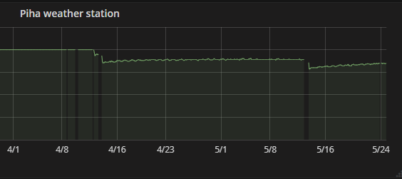
      I have some weird issues for which I need the WDG. Found and fixed one forever loop in I2C, but it did not fix all. Can't pinpoint the issue and now it drains the battery randomly by getting stuck somewhere after a week or a few months.

      Now I remember one experiment over a year ago with NRF51 based small board I used as mysensors remote. It has just one push button. This silicon version had problem with high current draw if waiting for pin change, so I just made it wakeup every 750ms, poll the button and if not pressed go back to sleep. CR2032 lasted way over a year. Had already forgotten that, good that you reminded!

      posted in Troubleshooting
      kisse66
      kisse66
    • RE: NRF52 watchdog problem (myBoardNRF5)

      yep.

      So if the description is wrong you can't really use WDG with sleeping sensors, unless the sleep period is less than WDG period ?

      posted in Troubleshooting
      kisse66
      kisse66
    • RE: NRF52 watchdog problem (myBoardNRF5)

      @monte understood, however the MySensorsNRF5 says

      "*The MySensors port for nRF5 supports using the Watchdog. You can use the same commands like defined in "avr/wdt.h" but disable cannot disable the watchdog. The watchdog is set to a period of 36h of CPU runtime.

      When the CPU is in a sleep mode, the watchdog timer is stopped*."

      Especially the suspend, or better lack of, under sleep is my problem. I could set it for >20 minutes (sleep time) perhaps, but if the CPU hangs the long period will use a lot of battery before recovering.

      posted in Troubleshooting
      kisse66
      kisse66
    • NRF52 watchdog problem (myBoardNRF5)

      Have I missed something or is there an issue with watchdog on NRF52 - watchdog does not get suspended when sleeping ?

      Using mysensors 2.3.1 and NRF52832 (Ebyte module) with myboardNRF5. I finally took the time to simplify the code and seems you only need minimum sketch to replicate this, just sleep for longer than wdg period.

      Disabling it manually (wdg_disable) before entering sleep does not change this. I did read the disable is not working, but should set it for long period. Now testing with 20s sleep and 10s wdg period, reboots at every sleep after 10s.

      Ignore the TEST_PIN stuff, it's there to make it easier to re-program (STlink can't connect while sleeping).
      wait() seems to be calling wdg_reset since it doesn't boot there.

      #define MY_DEBUG
      #define MY_RADIO_NRF5_ESB
      #include <MySensors.h>
      
      #ifdef MY_DEBUG
      #define DBG_PRINT(...)    Serial.print(__VA_ARGS__)
      #define DBG_PRINTLN(...)    Serial.println(__VA_ARGS__)
      #else
      #define DBG_PRINT(...)    do {} while (0)
      #define DBG_PRINTLN(...)    do {} while (0)
      #endif
      
      
      #define REED_PIN	18
      #define TEST_PIN	29	// sleep -> wait


      void setup()
      {
      	hwPinMode(REED_PIN, INPUT_PULLUP);
      	hwPinMode(TEST_PIN, INPUT_PULLUP);
      	Serial.begin(115200);
      
      	DBG_PRINT("PART: ");
      	DBG_PRINTLN((uint32_t)NRF_FICR->INFO.PART, HEX);
      	DBG_PRINT("VARIANT: ");
      	DBG_PRINTLN((uint32_t)NRF_FICR->INFO.VARIANT, HEX);
      
      	wdt_enable(10000);
      }
      
      void loop()
      {
      	int8_t stat=0;
      
      	if (digitalRead(TEST_PIN)) {
      		DBG_PRINTLN("sleep");
      		//wdt_disable();
      
      		//int8_t stat = smartSleep(digitalPinToInterrupt(REED_PIN), FALLING, 20000);
      		//int8_t stat = sleep(digitalPinToInterrupt(REED_PIN), FALLING, 20000);
      		int8_t stat = sleep(20000);
      
      		//wdt_enable(10000);
      	}
      	else {
      		DBG_PRINTLN("wait");
      		wait(20000);
      	}
      
      	DBG_PRINT("Wakeup, stat ");
      	DBG_PRINTLN(stat);
      	wdt_reset();
      }
      
      posted in Troubleshooting
      kisse66
      kisse66
    • RE: Battery based NRF52 sensor compile options?

      I tried all the options and maybe got a bit better battery life. However I have now found out, that the actual problem is not likely radio connection after all, but I2C related problem. Started getting more of random drops and after adding some more debug stuff I finally found, that it sometimes get stuck in HTU21 driver, that had a forever loop if there was no proper response. The driver code has later been modified (Adafruit) to avoid this loop. I had my own async version of it, which had the same bug (same code, but split into start() and read() to avoid the delay saving run time).

      So likely this random dead battery issue was forever loop draining the battery. Have no idea why it sometimes rebooted by itself, recently it has just died and after reset (battery off and back on) the battery is more or less empty.

      posted in Troubleshooting
      kisse66
      kisse66
    • RE: Battery based NRF52 sensor compile options?

      @nagelc

      good point, have to try. Actually I now have one repeater, but can remove it or maybe move it even closer and use that as static.

      posted in Troubleshooting
      kisse66
      kisse66
    • Battery based NRF52 sensor compile options?

      I have NRF52-based rain gauge. works well and got finally proper power consumption, but seem to have one problem to solve.
      It sends multiple sensor values and then goes to sleep for 20 minutes. This one is on the edge of radio coverage and occasionally seem to loose connection. Below is battery voltage measurement. You can see, that when there's a gap in the values (something wrong in radio coverage) the battery voltage drops rapidly, which suggests it does not sleep, but keeps trying something:

      0_1558718789617_2019-05-24 (2).png

      So the question is is there a good set of compile options to remove all checks etc, as I only want this one to send the values? If it fails just try again after the sleep period.

      Currently I have

      #define MY_SMART_SLEEP_WAIT_DURATION_MS  400
      #define MY_TRANSPORT_UPLINK_CHECK_DISABLED
      #define MY_TRANSPORT_WAIT_READY_MS  5000
      #define MY_RADIO_NRF5_ESB
      

      values are sent like

      send(msg);
      

      Any suggestions?

      posted in Troubleshooting
      kisse66
      kisse66
    • RE: E73 nrf52 sleep current

      @nca78

      about 27uA (Rigol DM3085) @3.2V. It only drops 1-2uA if I disconnect the sensors (all wires towards HTU21,BMP085,VEML6075, BH1750) which is about what the datasheet for those say under shutdown. So most is taken by NRF52. There can be other peripherals that could be turned off still before sleep maybe. Now I only handle the I2C errata and then shut it off before sleep (wire.end), the rest is in mysensors code for sleep.
      Sleep current does not change if I don't enable the DCDC. Perhaps the active current does a bit but can't measure it accurately (too fast).

      Just estimated that using AA-batteries it should last over 2 years. It only wakes up every 20min and runs about 400ms to send 7 values. But still I'd like to get better.

      This is my rain gauge / multisensor under upgrade. It was earlier powered by mega328+NRF24. Worked fine about a year, but then something happened and it started taking 2mA while sleeping. Didn't see any visible reason why.

      posted in Hardware
      kisse66
      kisse66
    • RE: E73 nrf52 sleep current

      @omemanti
      somehow missed that discussion...

      posted in Hardware
      kisse66
      kisse66
    • RE: E73 nrf52 sleep current

      @omemanti

      yes, I noticed it uses 3mA after re-program. Seems to keep debug circuits on. After power on/off goes down

      posted in Hardware
      kisse66
      kisse66
    • RE: E73 nrf52 sleep current

      Hmm, should read the manual?

      ERRATA [89] TWI: Static 400 µA current while using GPIOTE

      after adding the workaround before sleep

      *(volatile uint32_t *)0x40004FFC = 0;
      *(volatile uint32_t *)0x40004FFC;
      *(volatile uint32_t *)0x40004FFC = 1;
      

      sleep current goes down to 29uA. It's a bit high still but usable with AA batteries!

      NRF_FICR->INFO.VARIANT tells my chip is version AAB0

      posted in Hardware
      kisse66
      kisse66
    • RE: E73 nrf52 sleep current

      yes, you're right!
      Started experimenting and noticed I was stupid assuming the sensors have nothing to do with this because if I disconnect them while sleeping nothing changes. Well they do. The issue is I2C/TWI. If I comment out all sensorcode sleep current goes down to a few uA. It looks like I can do Wire.init() without this problem, but as soon as the first transaction is done it won't sleep properly. Wire.end() before sleeping does not help (disables TWI). So something changes after a transaction.
      To get it to minimum I commented all sensor code and only added (in setup())

      Wire.begin();
       Wire.beginTransmission(0x40);
      Wire.write(0xFE);
      Wire.endTransmission();
      

      if the last line is commented sleep works fine (this is reset command to HTU21, one byte transaction).
      I've tried undoing everything the wire-driver does before sleep, but can't figure out what helps.
      Any ideas?

      I think the 250uA difference is related to whether HFCLK is running or not - if the device uses 250uA while sleeping my STlinkV2 works fine (re-program). If it goes down to a few uamps STlink does not work ,"can't connect target" (no reset pin used).

      posted in Hardware
      kisse66
      kisse66
    • RE: E73 nrf52 sleep current

      hmm, I experimented with DCDC. Don't have correct inductors, but added 2x 4u7 axials in series and NRF_POWER->DCDCEN=1 in setup(). Active current did not change, but sleep went down to .25mA. Still way too high.

      Ordered SMD inductors, will see if it changes anything.

      posted in Hardware
      kisse66
      kisse66
    • E73 nrf52 sleep current

      I started experimenting with NRF52 /Ebyte E73 module and mysensors. Code works fine, but the issue is sleep current. It seems to take ~0.5mA under sleep(). Anyone else using batteries with this module?
      I'm on latest dev mysensors and arduino 1.8.8, sandeep nrf5 0.6.0.

      About a year ago I tried mysensors on small NRF51 board. It has the interrupt wakeup errata, so my code sleeps 750ms, wakes up and checks button press (it's a simple remote). If not pressed sleep again This has now lasted over half a year on CR2032, so I'm surpriced by the E73 sleep current.

      I do not have the inductor for DCDC, but as I read from Nordic articles it mainly saves on higher currents plus I don't know how to enable it on myseonsrs environment...

      The module seems to use ~16mA while working and then .5 after sleep() powered from 2x1.5V battery. It does have multiple I2C sensors, but if I disconnect the sensor cable while it's sleeping the .5mA does not change.

      posted in Hardware
      kisse66
      kisse66
    • RE: OTA FW update using I2C EEPROM

      @manutremo

      now merged, thanks!

      So this should fix the bootloader hang without pullups. The binary got a bit bigger again, but does not change much of anything since it still fits into 2k (1024W).
      I tested it with 8 and 16MHz pro mini with a few different EEPROMs (256 and 512kb).

      posted in Development
      kisse66
      kisse66
    • RE: OTA FW update using I2C EEPROM

      @manutremo

      been quite busy lately, can't promise anything but I'll try. It is an issue, but I don't think it's very urgent since if one uses I2C bootloader at least the pullups should be there.

      I was thinking of two things to try. Perhaps enabling the internal pullups may help (need to check if it works when TWI is enabled) or better fix the forever loops in the I2C code. There's already some retry counters for errors, but not everywhere. I guess when the pullups are not there TWI controller gets weird states and the code just loops retries somewhere. So perhaps add a counter to all the retrys (several locations in i2c.h, begin-label at readbyte would be my first choice. restart-label already has a counter).

      posted in Development
      kisse66
      kisse66
    • RE: Debug to a sd-card module?

      There's also OpenLog. Haven't tested yet, but just got one (China clone for about $4, Sparkfun $14.95). It's about the size of microSD card and logs all serial input. Spec says "2mA idle, 6mA at maximum recording rate" which means something like 2 weeks with 2xAA. One issue might be voltage, it says 3.3 - 12V input, don't know if it works unmodified with less, i.e. without step-up.

      I might also like to use the BT you included in your version.

      posted in Development
      kisse66
      kisse66
    • RE: OTA FW update using I2C EEPROM

      @manutremo

      Good to hear. I'm aware of one issue only as described above by @melwinek, haven't found time to fix. So "seems to work", but have done limited testing.

      Yes, you need older Arduino IDE version. I have actually two versions installed, latest and 1.0.6. Using latest for all except bootloader.
      I don't have to copy anything, I just cd to the bootloader located under old arduino tree (git cloned to Program Files (x86)\arduino-1.0.6\hardware\arduino\bootloaders\DualOptiboot) and do

      omake atmega328_e8

      from windows cmd prompt.

      This is forked from mysensors bootloader, maybe it could be merged back there some day with step by step instructions.

      posted in Development
      kisse66
      kisse66
    • RE: [SOLVED] Weird serial GW problem

      One more update:

      have not fully verified, but it seems like this was RF interference issue (maybe a transmitted ACK??).

      I added a 100n ceramic cap to power in line (at the GPIO connector) and 10nF caps from UART TX and RX to ground (small SMD caps at the connector). I also moved the antenna a bit higher by soldering coaxial cable to RFM and then peeling off the outer shield of the coax for the ~80mm. Problem gone!

      I'll add a ground plane to the antenna by putting aluminium tape to the top cover (missing here) and connecting the coax shield to it. Makes a better antenna and better shielding towards RPi. Have not re-checked range yet, but checked the UART signals with scope and the 10nF looks good as noise filter.

      0_1498848693734_WP_20170630_003 (2).jpg

      posted in Troubleshooting
      kisse66
      kisse66
    • RE: RS485 network not running... please help!

      Note about RS485:

      I've had (non-MySensors) issues with RS485 with some setups due to the fact that while the bus is not driven (no one sends anything) it's floating and not in idle state. This makes receivers pick random garbage. To make it stable you'd need to add pullup to the A line and pulldown to the B line (hope I remember polarity right way). Those will make sure the line stays idle. With two 120R terminators (both ends) the pullup/down needs to be quite small to create enough voltage across 60R. One could calculate (I think spec says 200mV), but I've used 470..680R with 5V system. Some interface modules may have these or similar current source on board.

      Termination with low speeds and short lines seems not so critical in practise.

      posted in Troubleshooting
      kisse66
      kisse66
    • RE: [SOLVED] Weird serial GW problem

      ok/FYI,
      seems there is nothing wrong with GW HW nor arduino code - I removed my GW module from RPi and used a USB serial to attach it to a windows PC running MYSController in GW mode instead. My nodejs controller connects to it rather than the local serial port and suddenly everything works, no more missing newlines. I even feed power only through FTDI cable and it still feels stable, even OTA completed fine.

      Before this I did try increasing Arduino serial TX_BUFFER to 128 bytes, but it had no visible effect.

      So it must be something in RPi serial port or nodejs serial interface. At this point I don't think its in my controller code (loosely based on the MySensorsSampleController), since I print the raw data from serial port first at the event handler and that already shows the missing data:

      }).on('data', function(rd) {
                                      logger.debug('gw' + i + " data: appending '" + rd + "'");
                                      appendRfData(rd.toString(), db, i);
      

      e.g. I saw

      [2017-06-14 12:23:06.975] [DEBUG] [default] - gw 2: appending '243;255;4;0;2;03'
      [2017-06-14 12:23:07.980] [DEBUG] [default] - gw 2: appending '243;255;'
      [2017-06-14 12:23:07.982] [DEBUG] [default] - gw 2: appending '4;0;2;03'
      [2017-06-14 12:23:07.984] [DEBUG] [default] - gw 2: appending '000200E7'
      [2017-06-14 12:23:07.986] [DEBUG] [default] - gw 2: appending '05
      '
      [2017-06-14 12:23:07.987] [DEBUG] [default] - rfm69 RX: 243;255;4;0;2;03243;255;4;0;2;03000200E705
      

      so one newline missing assembling two messages together.

      So problem kind of solved, at least there is no issue in MySensors side. It's been running now for 30 minutes, 3 ping-pong test msg per second and none lost.

      posted in Troubleshooting
      kisse66
      kisse66
    • [SOLVED] Weird serial GW problem

      Been looking into this a few days now, but maybe it's worth asking if someone else has seen similar:

      Have RFM69HW based serial GW on 8MHz pro mini. This is then hooked up to RPi2 via direct serial (RPi runs a nodejs based simple controller). I'm using latest (few days ago) dev branch from git. Radio does have separate regulator and proper bypass caps. Serial GW sketch is empty, i.e. no extra functionality. About default settings, new RFM driver, no signing, no encryption.

      Basically it works, but there are two issues. Main one is the controller over the serial line (added a debug print of raw data in serial event handler) sometimes gets concatenated messages, i.e. the separating newline is randomly missing. This makes the message parser fail with incorrect payload for instance. This is very random and seems it gets more likely as I increase the rate of messaging (attempting OTA for instance). Originally I used the default 38600 bps, but tried to increase it to 57600. No real change and the message rate I see should not exceed the serial speed (a few msg per second). Not only connected to the message length as I have seen it also with short messages (2 byte payload), but mostly happens when attempting OTA.
      Slow sensors seen to work fine, but OTA never goes through. When testing there's only GW and test node powered.

      Another issue is lost messages towards the GW. Haven't looked deeper yet, but I do get radio acks every time, but sometimes one message just never appears out of the gw (nodes are a few meters apart with good RSSI). I mean nothing comes out.

      I'll keep looking and simplifying the setup, but if someone has seen something like this I'd appreciate any info.

      posted in Troubleshooting
      kisse66
      kisse66
    • RE: OTA FW update using I2C EEPROM

      @melwinek
      Thanks, good info. Middle of vacation activities here but I looked the code a bit more. It does have the retry limit, but also forever loops with certain I2C events. Can be fixed quite easily I believe. I need to setup test bed for it to see myself.

      Not an urgent thing I believe?

      posted in Development
      kisse66
      kisse66
    • RE: OTA FW update using I2C EEPROM

      @melwinek
      hmm, interesting. There should be a timeout, but I need to re-check. Are the I2C pins floating or are the pullup resistors still there?

      posted in Development
      kisse66
      kisse66
    • RE: OTA FW update using I2C EEPROM

      @Nca78
      Good question - Have only tested 256 and 512kbit (32/64kB), nothing bigger than 64kB. Unfortunately I2C protocol is slightly different between different EEPROMs, so code does have limitations. There's two sides of it. MySensors side now uses extEEPROM underneath, so what it supports should work. Address type is 32-bit, so the interface supports >64kB. Haven't checked the code, but at least it defines 2Mbit type (see extEEPROM.h). My patch now assumes EEPROM is 32kB (64 fine) as it's enough for mega328.

      Bigger issue is the bootloader, which has more assumptions. Likely not working as is for anything bigger than 64kB. Would be interesting to hear if someone can try, I don't have larger EEPROMs.

      posted in Development
      kisse66
      kisse66
    • RE: OTA FW update using I2C EEPROM

      It's up to the maintainers to decide if it's good enough implementation and then when to merge the PR. There has been no comments yet.

      I don't like to update my version now as it's pending.

      posted in Development
      kisse66
      kisse66
    • RE: OTA FW update using I2C EEPROM

      The bootloader at github is not verified yet, it's an updated version from pieces I used to test. That's why I haven't mentioned it yet here. Looks like linking adresses are wrong. Will fix but can't promise when. Might have time next week.

      If you need it now, try lowering the --section-start=.text=0x7c00 at Makefile line 618 to 0x7a00 (or down to 0x7800). The 7c00 only allow for 1kB bootloader. You also need to have fuses set for max boot block. Luckily they are so as default in many pro mini's at least.

      I'll see if I still have the binary I used. It's for 8MHz pro mini.

      I'm interested in hearing if it works on your case as well. I'll be doing some more testing also and update github accordingly.

      posted in Development
      kisse66
      kisse66
    • RE: OTA FW update using I2C EEPROM

      It seems to work now. Boot loader needs some more work, but MySensors part should be usable. If someone likes to have a look you can find it at http://github.com/kisse66/MySensors fork. By default it still uses SPI flash and works just like the original. To use I2C EEPROM uncomment (MyConfig.h) or define MY_OTA_USE_I2C_EEPROM in your sketch. You'll need also MY_OTA_FIRMWARE_FEATURE of course.
      My code uses Wire library for I2C (new driver) and defaults to address 0x50 (real I2C address 0xA0) that most EEPROMs use I think. EEPROM has to use 16-bit addresses, 24(L)C256 or 512 should work.
      Only tested with MYScontroller, pro mini 8MHz with nRF24 and 24LC512 EEPROM on AVR HW I2C.

      Do note that I'm still working on the bootloader part which you'll need to make this actually work. I have a "seems like working" hack, but it needs some more work. Approach is to use DualOptiboot code and add option there for alternate I2C. I'll publish it when it's getting a bit better.

      posted in Development
      kisse66
      kisse66
    • OTA FW update using I2C EEPROM

      Hi,

      I have boards with I2C EEPROM (32 or 64kB) instead of a SPI flash already supported via dualoptiboot. Been looking a bit but haven't found any discussion about such so far? Sorry if I have missed one.
      I have both nRF24 and RFM69 radios in use and going to mysensors from my earlier proprietary system.

      Anyway I already started implementing changes to dualoptiboot and mysensors OTA code. IF someone knows of existing work please do point me there so I can stop working on it. My idea is to make a simple EEPROM (24(L)Cxxx) driver that looks like the SPI flash driver to make the changes to mysensors minimal. Seems so far only a few lines are needed in addition to the new driver. Bootloader is a bit more work. Any comments about this approach (in case it starts working well and someone else likes to use it) ?

      posted in Development
      kisse66
      kisse66