Tested a arduino node with a arduino gateway (433 rfm69hw) that works fine, used the same node code as posted above. This narrows it down the RPI Zero W gateway.
M
MaDDoG
@MaDDoG
Posts
-
PIzeroW + RFM69HW + arduino node connection problem -
PIzeroW + RFM69HW + arduino node connection problemAn other update:
Did a radio test:
Test program (only difference is the node id):
// ***************************************************************************************
// Sample RFM69 sketch for Moteino to illustrate:
//   - sending
//   - receiving
//   - automatic transmission control
//   - button reading/interrupts
// ***************************************************************************************
// When you press the button on the SENDER Moteino, it will send a short message to the
// RECEIVER Moteino and wait for an ACK (acknowledgement that message was received) from
// the RECEIVER Moteino. If the ACK was received, the SENDER will blink the onboard LED
// a few times. The RECEIVER listens to a specific token, and it alternates the onboard LED
// state from HIGH to LOW or vice versa whenever this token is received.
// ***************************************************************************************
// Hardware setup:
// ***************************************************************************************
// On the sender, hook up a momentary tactile button to D3 like this:
//          __-__
//        __|   |___
// GND ----> BTN ----> D3 (D11 on MoteinoMEGA)
// Load this sketch on the RECEIVER with NODEID=RECEIVER (adjust in config section below)
// Load this sketch on the SENDER with NODEID=SENDER (adjust in config section below)
// RFM69 library and code by Felix Rusu - felix@lowpowerlab.com
// Get libraries at: https://github.com/LowPowerLab/
// Make sure you adjust the settings in the configuration section below !!!
// **********************************************************************************
// Copyright Felix Rusu 2016, http://www.LowPowerLab.com/contact
// **********************************************************************************
// License
// **********************************************************************************
// This program is free software; you can redistribute it
// and/or modify it under the terms of the GNU General
// Public License as published by the Free Software
// Foundation; either version 3 of the License, or
// (at your option) any later version.
//
// This program is distributed in the hope that it will
// be useful, but WITHOUT ANY WARRANTY; without even the
// implied warranty of MERCHANTABILITY or FITNESS FOR A
// PARTICULAR PURPOSE. See the GNU General Public
// License for more details.
//
// Licence can be viewed at
// http://www.gnu.org/licenses/gpl-3.0.txt
//
// Please maintain this license information along with authorship
// and copyright notices in any redistribution of this code
// **********************************************************************************
#include <RFM69.h>         //get it here: https://www.github.com/lowpowerlab/rfm69
#include <RFM69_ATC.h>     //get it here: https://github.com/lowpowerlab/RFM69
#include <SPI.h>           //included with Arduino IDE (www.arduino.cc)
#include <LowPower.h>      //get library from: https://github.com/lowpowerlab/lowpower

//****************************************************************************************************************
//**** IMPORTANT RADIO SETTINGS - YOU MUST CHANGE/CONFIGURE TO MATCH YOUR HARDWARE TRANSCEIVER CONFIGURATION! ****
//****************************************************************************************************************
#define NETWORKID     100  //the same on all nodes that talk to each other
#define RECEIVER      1    //unique ID of the gateway/receiver
#define SENDER        2
#define NODEID        SENDER  //change to "SENDER" if this is the sender node (the one with the button)
//Match frequency to the hardware version of the radio on your Moteino (uncomment one):
#define FREQUENCY     RF69_433MHZ
//#define FREQUENCY     RF69_868MHZ
//#define FREQUENCY     RF69_915MHZ
#define ENCRYPTKEY    "sampleEncryptKey" //exactly the same 16 characters/bytes on all nodes!
#define IS_RFM69HW_HCW  //uncomment only for RFM69HW/HCW! Leave out if you have RFM69W/CW!
//*****************************************************************************************************************************
#define ENABLE_ATC      //comment out this line to disable AUTO TRANSMISSION CONTROL
#define ATC_RSSI        -75
//*********************************************************************************************
#define SERIAL_BAUD   115200
#ifdef __AVR_ATmega1284P__
  #define LED           15 // Moteino MEGAs have LEDs on D15
  #define BUTTON_INT    1 //user button on interrupt 1 (D3)
  #define BUTTON_PIN    11 //user button on interrupt 1 (D3)
#else
  #define LED           13 // Moteinos have LEDs on D9
  #define BUTTON_INT    1 //user button on interrupt 1 (D3)
  #define BUTTON_PIN    3 //user button on interrupt 1 (D3)
#endif

#define LED_GREEN       4 //GREEN LED on the SENDER
#define LED_RED         5 //RED LED on the SENDER
#define RX_TOGGLE_PIN   7 //GPIO to toggle on the RECEIVER

#ifdef ENABLE_ATC
  RFM69_ATC radio;
#else
  RFM69 radio;
#endif

void setup() {
  Serial.begin(SERIAL_BAUD);
  radio.initialize(FREQUENCY,NODEID,NETWORKID);
#ifdef IS_RFM69HW_HCW
  radio.setHighPower(); //must include this only for RFM69HW/HCW!
#endif
  radio.encrypt(ENCRYPTKEY);

#ifdef ENABLE_ATC
  radio.enableAutoPower(ATC_RSSI);
#endif

  char buff[50];
  sprintf(buff, "\nListening at %d Mhz...", FREQUENCY==RF69_433MHZ ? 433 : FREQUENCY==RF69_868MHZ ? 868 : 915);
  Serial.println(buff);
  Serial.flush();
  pinMode(BUTTON_PIN, INPUT_PULLUP);
  pinMode(LED, OUTPUT);
  attachInterrupt(BUTTON_INT, handleButton, FALLING);

  pinMode(LED_GREEN, OUTPUT);
  pinMode(LED_RED, OUTPUT);
  pinMode(RX_TOGGLE_PIN, OUTPUT);
  digitalWrite(LED_GREEN, LOW);
  digitalWrite(LED_RED, HIGH);
}

//******** THIS IS INTERRUPT BASED DEBOUNCING FOR BUTTON ATTACHED TO D3 (INTERRUPT 1)
#define FLAG_INTERRUPT 0x01
volatile int mainEventFlags = 0;
boolean buttonPressed = false;
void handleButton()
{
  mainEventFlags |= FLAG_INTERRUPT;
}

byte LEDSTATE=LOW; //LOW=0
void loop() {
  //******** THIS IS INTERRUPT BASED DEBOUNCING FOR BUTTON ATTACHED TO D3 (INTERRUPT 1)
  if (mainEventFlags & FLAG_INTERRUPT)
  {
    LowPower.powerDown(SLEEP_120MS, ADC_OFF, BOD_ON);
    mainEventFlags &= ~FLAG_INTERRUPT;
    if (!digitalRead(BUTTON_PIN)) {
      buttonPressed=true;
    }
  }

  if (buttonPressed)
  {
    Serial.println("Button pressed!");
    buttonPressed = false;

    if(LEDSTATE==LOW)
    {
      LEDSTATE=HIGH;
      digitalWrite(LED_GREEN, HIGH);
      digitalWrite(LED_RED, LOW);
    }
    else
    {
      LEDSTATE=LOW;
      digitalWrite(LED_GREEN, LOW);
      digitalWrite(LED_RED, HIGH);
    }

    if (radio.sendWithRetry(RECEIVER, "Hi", 2)) //target node Id, message as string or byte array, message length
      Blink(LED, 40, 3); //blink LED 3 times, 40ms between blinks
  }

  //check if something was received (could be an interrupt from the radio)
  if (radio.receiveDone())
  {
    //print message received to serial
    Serial.print('[');Serial.print(radio.SENDERID);Serial.print("] ");
    Serial.print((char*)radio.DATA);
    Serial.print("   [RX_RSSI:");Serial.print(radio.RSSI);Serial.print("]");
    Serial.println();

    //check if received message is 2 bytes long, and check if the message is specifically "Hi"
    if (radio.DATALEN==2 && radio.DATA[0]=='H' && radio.DATA[1]=='i')
    {
      if(LEDSTATE==LOW)
        LEDSTATE=HIGH;
      else LEDSTATE=LOW;
      digitalWrite(LED, LEDSTATE);
      digitalWrite(RX_TOGGLE_PIN, LEDSTATE);
    }

    //check if sender wanted an ACK
    if (radio.ACKRequested())
    {
      radio.sendACK();
      Serial.print(" - ACK sent");
    }
  }

  radio.receiveDone(); //put radio in RX mode
  Serial.flush(); //make sure all serial data is clocked out before sleeping the MCU
  LowPower.powerDown(SLEEP_8S, ADC_OFF, BOD_ON); //sleep Moteino in low power mode (to save battery)
}

void Blink(byte PIN, byte DELAY_MS, byte loops)
{
  for (byte i=0; i<loops; i++)
  {
    digitalWrite(PIN,HIGH);
    delay(DELAY_MS);
    digitalWrite(PIN,LOW);
    delay(DELAY_MS);
  }
}
which results in:
Listening at 433 Mhz...
[2] Hi   [RX_RSSI:-56]
 - ACK sent[2] Hi   [RX_RSSI:-58]
 - ACK sent[2] Hi   [RX_RSSI:-58]
 - ACK sent[2] Hi   [RX_RSSI:-57]
 - ACK sent[2] Hi   [RX_RSSI:-57]
 - ACK sent[2] Hi   [RX_RSSI:-59]
 - ACK sent[2] Hi   [RX_RSSI:-59]
 - ACK sent[2] Hi   [RX_RSSI:-59]
 - ACK sent[2] Hi   [RX_RSSI:-59]
 - ACK sent[2] Hi   [RX_RSSI:-59]
 - ACK sent[2] Hi   [RX_RSSI:-60]
 - ACK sent[2] Hi   [RX_RSSI:-60]
 - ACK sent[2] Hi   [RX_RSSI:-61]
 - ACK sent[2] Hi   [RX_RSSI:-62]
 - ACK sent[2] Hi   [RX_RSSI:-62]
 - ACK sent[2] Hi   [RX_RSSI:-62]
 - ACK sent[2] Hi   [RX_RSSI:-63]
 - ACK sent[2] Hi   [RX_RSSI:-62]
 - ACK sent[2] Hi   [RX_RSSI:-64]
 - ACK sent[2] Hi   [RX_RSSI:-64]
 - ACK sent[2] Hi   [RX_RSSI:-65]
So my radio"s and arduino"s are fine.
Which brings me to the question is the Raspberry pi zero w not supported? Will try the RPI3 tomorrow.
-
PIzeroW + RFM69HW + arduino node connection problemI just tried the nrf24 and those work fine. Im stuck, all i can think is: rfm69 issue
-
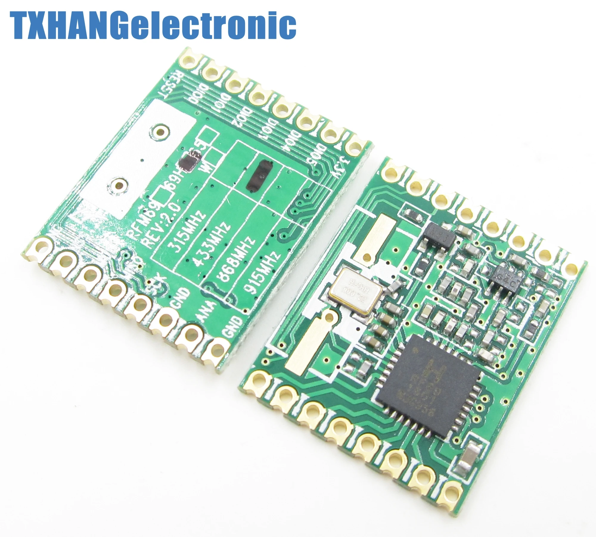
PIzeroW + RFM69HW + arduino node connection problemSame as I have, but have a look at the markings, only the H is marked.. same like mine
-
PIzeroW + RFM69HW + arduino node connection problem@gohan I surely orderd the HW but its marked with only the H and now the HW. Is there any difference between them?
-
PIzeroW + RFM69HW + arduino node connection problem@gohan Checked it, everything is connected correctly. One thing I saw, it is the rfm69H not HW. Don't really know the difference.
-
PIzeroW + RFM69HW + arduino node connection problemNo there is no output to the sensor, this is the only output i get, which is the controller i think:
mysgw: Client 0 connected
mysgw: Client 0: 0;255;3;0;18;
mysgw: Client 0: 255;255;3;0;20;
mysgw: TSF:MSG:SEND,0-0-255-255,s=255,c=3,t=20,pt=0,l=0,sg=0,ft=0,st=OK:
mysgw: Client 0: 0;255;3;0;18;
mysgw: Client 0: 0;255;3;0;2;
mysgw: TSM:READY:NWD REQ
mysgw: TSF:MSG:SEND,0-0-255-255,s=255,c=3,t=20,pt=0,l=0,sg=0,ft=0,st=OK:
Changing the distance does not help
-
PIzeroW + RFM69HW + arduino node connection problemHi All,
For my project I want to use the PIzeroW as the GW and Controller and multiple GPS sensors.
My setup:
PiZeroW with raspian stretch + rfm69HW using dev branch
Controller: Mycontroller.org
build the gateway:
./configure --my-transport=rfm69 --my-rfm69-frequency=433 --my-is-rfm69hw --my-gateway=ethernet --my-port=5003Got one warning:
g++ -MT build/examples_linux/mysgw.o -MMD -MP -march=armv6zk -mtune=arm1176jzf-s -mfpu=vfp -mfloat-abi=hard -DMY_RADIO_RFM69 -DMY_RFM69_NEW_DRIVER -DMY_GATEWAY_LINUX -DMY_DEBUG -DLINUX_SPI_BCM -DLINUX_ARCH_RASPBERRYPI -DMY_PORT=5003 -DMY_IS_RFM69HW -DMY_RFM69_FREQUENCY=RFM69_433MHZ  -Ofast -g -Wall -Wextra  -I. -I./core -I./drivers/Linux -I./drivers/BCM -c examples_linux/mysgw.cpp -o build/examples_linux/mysgw.o
In file included from ./MySensors.h:328:0,
                 from examples_linux/mysgw.cpp:83:
./drivers/RFM69/new/RFM69_new.cpp:662:12: warning: ‘void RFM69_ATCmode(bool, int16_t)’ defined but not used [-Wunused-function]
 LOCAL void RFM69_ATCmode(const bool onOff, const int16_t targetRSSI)
Some unused define (bug?)
Right thing is build! Lets start:
sudo ./bin/mysgw -dOutput: mysgw: Starting gateway... mysgw: Protocol version - 2.2.0-beta mysgw: MCO:BGN:INIT GW,CP=RPNG----,VER=2.2.0-beta mysgw: TSF:LRT:OK mysgw: TSM:INIT mysgw: TSF:WUR:MS=0 mysgw: TSM:INIT:TSP OK mysgw: TSM:INIT:GW MODE mysgw: TSM:READY:ID=0,PAR=0,DIS=0 mysgw: MCO:REG:NOT NEEDED mysgw: Listening for connections on 0.0.0.0:5003 mysgw: MCO:BGN:STP mysgw: MCO:BGN:INIT OK,TSP=1 mysgw: New connection from 127.0.0.1 mysgw: Client 0 connectedNice! Its working!
Well all good so far! Lets make an arduino node. Ok.. start simple:
Using version 2.1.1
// Enable debug prints to serial monitor
#define MY_DEBUG

// Enable and select radio type attached
#define MY_RADIO_RFM69
#define MY_RFM69_NEW_DRIVER
#define MY_DEBUG_VERBOSE_RFM69
#define MY_RFM69_FREQUENCY RF69_433MHZ
#define MY_IS_RFM69HW
#define MY_RFM69_NETWORKID 100
#define MY_NODE_ID 1

#define CHILD_ID 1
#define OPEN 1
#define CLOSE 0

#include <MySensors.h>
#include <SPI.h>


MyMessage msg(CHILD_ID, V_TRIPPED);

uint8_t value = OPEN;

void presentation()
{
    present(CHILD_ID, S_DOOR);
}

void loop()
{
    value = value == OPEN ? CLOSE : OPEN;
    send(msg.set(value));
    sleep(10000);
}
And this is where im stuck:
Radios are fine, there are tested, voltages are fine 3.3V powered by a powersupply since the pi zero and arduino cant supply the current. Ok software problem then? Using this as a base: what is wrong?
Output:
0 MCO:BGN:INIT NODE,CP=RRNNA--,VER=2.1.1
4 TSM:INIT
4 TSF:WUR:MS=0
8 TSM:INIT:TSP OK
10 TSM:INIT:STATID=1
12 TSF:SID:OK,ID=1
14 TSM:FPAR
145 TSF:MSG:SEND,1-1-255-255,s=255,c=3,t=7,pt=0,l=0,sg=0,ft=0,st=OK:
2152 !TSM:FPAR:NO REPLY
2154 TSM:FPAR
2285 TSF:MSG:SEND,1-1-255-255,s=255,c=3,t=7,pt=0,l=0,sg=0,ft=0,st=OK:
4292 !TSM:FPAR:NO REPLY
4294 TSM:FPAR
4425 TSF:MSG:SEND,1-1-255-255,s=255,c=3,t=7,pt=0,l=0,sg=0,ft=0,st=OK:
6432 !TSM:FPAR:NO REPLY
6434 TSM:FPAR
6565 TSF:MSG:SEND,1-1-255-255,s=255,c=3,t=7,pt=0,l=0,sg=0,ft=0,st=OK:
8574 !TSM:FPAR:FAIL
8577 TSM:FAIL:CNT=1
8579 TSM:FAIL:PDT
18583 TSM:FAIL:RE-INIT
18585 TSM:INIT
18589 TSM:INIT:TSP OK
18591 TSM:INIT:STATID=1
18593 TSF:SID:OK,ID=1
18595 TSM:FPAR
18728 TSF:MSG:SEND,1-1-255-255,s=255,c=3,t=7,pt=0,l=0,sg=0,ft=0,st=OK:
20736 !TSM:FPAR:NO REPLY
20738 TSM:FPAR
20869 TSF:MSG:SEND,1-1-255-255,s=255,c=3,t=7,pt=0,l=0,sg=0,ft=0,st=OK:
22876 !TSM:FPAR:NO REPLY
22878 TSM:FPAR
23009 TSF:MSG:SEND,1-1-255-255,s=255,c=3,t=7,pt=0,l=0,sg=0,ft=0,st=OK:
25016 !TSM:FPAR:NO REPLY
25018 TSM:FPAR
25149 TSF:MSG:SEND,1-1-255-255,s=255,c=3,t=7,pt=0,l=0,sg=0,ft=0,st=OK:
kind regards,
MaDDoG