@mfalkvidd Yes i did but has you can see even when the hall sensor is not connected the arduino sends data and the water increases in the the gateway. I can work on the SEND_FREQUENCY and see if it fix this problem.
Thnaks for the replay
@mfalkvidd Yes i did but has you can see even when the hall sensor is not connected the arduino sends data and the water increases in the the gateway. I can work on the SEND_FREQUENCY and see if it fix this problem.
Thnaks for the replay
Hi.
I'm using this water flow sensor 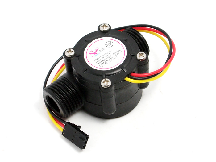 using the code available from the pulse water meter but the values i'me getting are all rong...
I'm triyng to adapt the code to this water flow sensor with no luck.
Could anyone give me an help with the code?
Thanks in advance.
@bart59 Yes i'm using the 3,3v from the arduino and i always connect everything with the arduino power off. Give me mor 5 minutes and i'll upload a photo from my sensor going to bring it inside home.
@mfalkvidd i think i don't have anything magnetic on the place were i'm putting the arduino and the sensor at this time.
Thanks for the replays.
Hi. yesterday i disassembled the rain gauge circuit removed from it the reed switch and created a new circuit.
I have connnected the reed switch to GND and PIN3 whit 10kOhm resistor.
I'll post an image tonight.
Up until now the values i'me getting from this new circuit is:

Values i'm getting from serial port:
Rain last 24 hours:
1.80
Rain last 48 hours:
12481.94
Rain last 72 hours:
28210.34
Rain last 96 hours:
43938.74
Rain last 120 hours:
59667.14
read and drop: 6-6-255 s=255,c=3,t=7,pt=0,l=0,sg=0:
read and drop: 6-6-255 s=255,c=3,t=7,pt=0,l=0,sg=0:
read and drop: 5-5-255 s=255,c=3,t=7,pt=0,l=0,sg=0:
read and drop: 6-6-255 s=255,c=3,t=7,pt=0,l=0,sg=0:
Seeing the graphic and this values it seems the problem i was having is fixed...
But tonight i'm going do spread some water over the bucket to see if i get any values and not just 0
This is my new code for this sensor and reajusted to library 2.1.1
/**
 * The MySensors Arduino library handles the wireless radio link and protocol
 * between your home built sensors/actuators and HA controller of choice.
 * The sensors forms a self healing radio network with optional repeaters. Each
 * repeater and gateway builds a routing tables in EEPROM which keeps track of the
 * network topology allowing messages to be routed to nodes.
 *
 * Created by Henrik Ekblad <henrik.ekblad@mysensors.org>
 * Copyright (C) 2013-2015 Sensnology AB
 * Full contributor list: https://github.com/mysensors/Arduino/graphs/contributors
 *
 * Documentation: http://www.mysensors.org
 * Support Forum: http://forum.mysensors.org
 *
 * This program is free software; you can redistribute it and/or
 * modify it under the terms of the GNU General Public License
 * version 2 as published by the Free Software Foundation.
 *
 *******************************
 *
 * REVISION HISTORY
 * Version 1.0 - epierre
 * Contribution: bulldoglowell, gizmocuz
 *
 * DESCRIPTION
 * Connect sensor ML8511 / Arduino:
 *
 *  3.3V = 3.3V
 *  OUT = A0
 *  GND = GND
 *  EN = 3.3V
 *  Arduino 3.3V = Arduino A1
 *
 * License: Attribution-NonCommercial-ShareAlike 3.0 Unported (CC BY-NC-SA 3.0)
 */

// Enable debug prints
#define MY_DEBUG

// Enable and select radio type attached
#define MY_RADIO_NRF24
//#define MY_RADIO_RFM69
//#define MY_RS485

#include <SPI.h>
#include <MySensors.h>
#include <SPI.h>

//Hardware pin definitions
int REF_3V3 = A1;
int UVOUT = A0;

#define CHILD_ID_UV 0

unsigned long SLEEP_TIME = 30*1000; // Sleep time between reads (in milliseconds)

MyMessage uvMsg(CHILD_ID_UV, V_UV);

float lastUV = -1;
unsigned long lastSend =0;

void presentation()
{
  // Send the sketch version information to the gateway and Controller
  sendSketchInfo("UV Sensor", "3.0");

  // Register all sensors to gateway (they will be created as child devices)
  present(CHILD_ID_UV, S_UV, "ML8511_UV");
}

void setup()
{
  //gw.begin(NULL, 9, true);
  pinMode(UVOUT, INPUT);
  pinMode(REF_3V3, INPUT);
}

void loop()
{
  int uvLevel = averageAnalogRead(UVOUT);
  int refLevel = averageAnalogRead(REF_3V3);
  unsigned long currentTime = millis();

  //Use the 3.3V power pin as a reference to get a very accurate output value from sensor
  float outputVoltage = 3.3 / refLevel * uvLevel;

  //float outputVoltage = 5.0 * uvLevel/1024;
  float uvIntensity = mapfloat(outputVoltage, 0.99, 2.8, 0.0, 15.0);          //Convert the voltage to a UV intensity level

  Serial.print("output: ");
  Serial.print(refLevel);

  Serial.print("ML8511 output: ");
  Serial.print(uvLevel);

  Serial.print(" / ML8511 voltage: ");
  Serial.print(outputVoltage);

  Serial.print(" / UV Intensity (mW/cm^2): ");
  Serial.print(uvIntensity);

  Serial.println();

  if ((uvIntensity != lastUV)||(currentTime-lastSend >= 5*60*1000))
  {
      lastSend=currentTime;
      send(uvMsg.set(uvIntensity,2));
      lastUV = uvIntensity;
  }
  delay(100);
}

//Takes an average of readings on a given pin
//Returns the average
int averageAnalogRead(int pinToRead)
{
  byte numberOfReadings = 8;
  unsigned int runningValue = 0;

  for(int x = 0 ; x < numberOfReadings ; x++)
    runningValue += analogRead(pinToRead);
  runningValue /= numberOfReadings;

  return(runningValue);
}

//The Arduino Map function but for floats
//From: http://forum.arduino.cc/index.php?topic=3922.0
float mapfloat(float x, float in_min, float in_max, float out_min, float out_max)
{
  return (x - in_min) * (out_max - out_min) / (in_max - in_min) + out_min;
}```