@Boots33 I have change to an arduino nano but still get some strange values. I'm going to make some changes over this project and see again what ill get.
Thanks for all the help.
@Boots33 I have change to an arduino nano but still get some strange values. I'm going to make some changes over this project and see again what ill get.
Thanks for all the help.
@zboblamont I have already read that pdf there they say this:
"The design of the Magnetic Transmission reduces the number of components
Operating in the water, increasing the reliability of the meter."
They also say this in the pdf:
"Any of these models can be supplied ready to receive the
Pulse transmission (see tele-count catalog). Ex .: MSV 1520t"
In this last information i made a search for MSV 1520t were i found again another pdf that talks about my water meter.
Here's the link: http://resopre.pt/conteudo.php?fam=CONTADORES,CONT_DOMESTICOS&pag=AGUA_RESOPRE.PT&detail=693
You can see 5 water meters on that link all off them say's Magnetic Transmission "Transmissão magnética" but has you can see none off them look like mine. Has i can understand mine is the more basic off them all i do belive that i have the first generation off this water meters.
I have done one last test yesterday leaving a water tap open and passed the hall sensor all over the water meter from side to side and top to bottom and never got any impulse digital led light turning on.
The led did turned on when i put my finger in the top off the sensor or in cables near the pins of the sensor.
@bart59 and @mfalkvidd Thanks for all the help. Today i toke the sensor to the water meter and for my luck my water meter is too old 1997 and no mater the position i put the hall sensor it just doesn't get any pulse at all :( at this time i really don't now what to use to get the data from my water meter...
I have already tried also the TCRT5000 and also does not work. Here's an image from my water meter
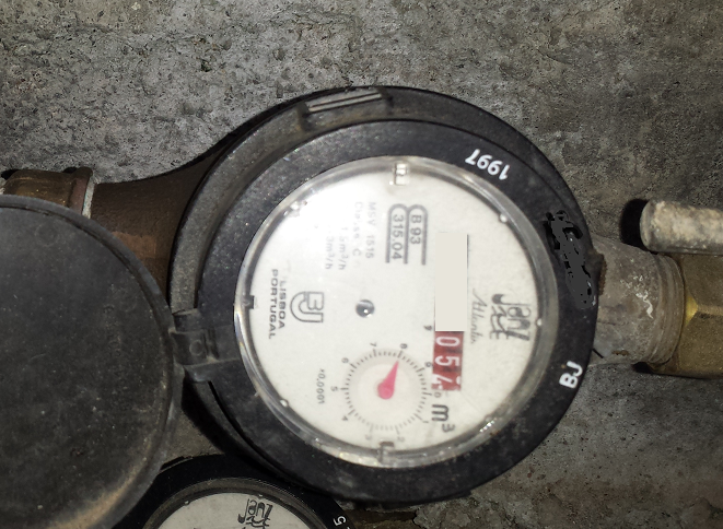
The TCRT5000 when i put over the glass the green led stays always on but when i remove it from the glass and point it to the black part of my meter the green led goes off the sensor is working ok but the glass from my meter does not help at all.
Any sugestions off other sensors i can try or use ?
I think i have fix my problem. I have been playing with the code and the sensor and notice that the power led and data led on the sensor were always on no mater the digital pin i was trying to use.
This also happened with the analog pin A0.
In one last attempt i decided to use the digital pin 3 with the resistor soldered on the board for sensors like dallas and dht11 or dht22.
Now the first thing i had noticed was the data led was not on and now it only comes on when i passe a magnet under my sensor... it does not count any pulsecount if i passe the magnet over the sensor only under it.
Counted the times i had passed the magnet under the sensor and my gateway received te exact number 30 times = 0.030 volume and now the volume is stop at this number no more ghost encrease numbers.
Tomorrow morning i'm going to mount the sensor over the water meter to see if this finaly works.
The only problem i'm getting now is some NACK over the transmissions... like this:
6604747 TSF:MSG:SEND,1-1-0-0,s=1,c=1,t=25,pt=5,l=4,sg=0,ft=3,st=OK:30
volume:0.030
604794 !TSF:MSG:SEND,1-1-0-0,s=1,c=1,t=35,pt=7,l=5,sg=0,ft=0,st=NACK:0.030
pulsecount:30
634781 !TSF:MSG:SEND,1-1-0-0,s=1,c=1,t=25,pt=5,l=4,sg=0,ft=1,st=NACK:30
volume:0.030
634828 !TSF:MSG:SEND,1-1-0-0,s=1,c=1,t=35,pt=7,l=5,sg=0,ft=2,st=NACK:0.030
Ok here's the photo off my sensor. On my code i'm using the digital pin2 since digital pin3 has a resistor for Dallas and dht sensors but i'm not using them at this time. This arduino is only for water meter.
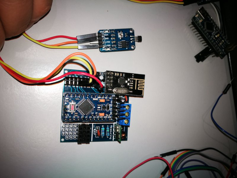
@bart59 Yes i'm using the 3,3v from the arduino and i always connect everything with the arduino power off. Give me mor 5 minutes and i'll upload a photo from my sensor going to bring it inside home.
@mfalkvidd i think i don't have anything magnetic on the place were i'm putting the arduino and the sensor at this time.
Thanks for the replays.
New update.... have change the arduino mini pro for another one flash a new code a new sensor and again i'm getting volume data when the sensor is not near the water meter. I dont understand what's happening.
@bart59 Thanks have done like you said and did clean the data from the gateway.
All day until 1h ago i had left my arduino connected on my pc and i did like mfalkvidd said connecting the digital pin 2 to gnd and my arduino did not send any strange value to the gateway always seend volume 0.00 this was perfect.
Now that i'm at home i had connect my arduino to the sensor 3.3v gnd and digital pin2 and in the first log there it was value increase on volume when my sensor was in front off me...
I have a arduino nano pro 3.3v on easy pcb board and i'm using the hall sensor i dont see why i'm getting this problem...
I have a WiFi AP inside home and my sensor is outside.
Even the water flow says i have a 2.00 L/min when the sensor is not near the water meter.
@mfalkvidd Thanks. Have now connected the digital pin2 to gnd and in the last 1h the values are always 0.000 going to leave it this way until night since now i'm at work. I would like to find out what was creating the spurious interrupts??
Other thing that ill find out tonight is when i connect the sensor to the arduino will it create rong data or will it only send real data only when the water meter starts running water...
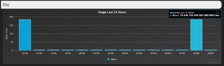
One more thing today at 8:00 when i did the pin2 to gnd the first "boot" over domoticz i got this value as you can see on the image below. Is this normal? Have been trying to deleted but it wont go away.
Once again thanks for your help.
Have been working with the code and have found one strange thing. When my sensor sends data to the gateway "domoticz" the gateway sends a value to the sensor. The strange thing is that my arduino does not have any sensor connected and sow the data send is zero but my gateway sends akways a positive value and increases this value every time it sends data to the arduino.
Even if i go to the arduino code and set the volume and pulseCount to 0 flash it to the arduino, load the value of zero to the gateway and then e flash the same code but this time i remove the volume and pulseCount to 0 the first time the arduino sends data to the gateway it always receive a value insted of zero since i dont have the hall sensor connected to the arduino.
I'm using a arduino mini pro 3.3v on a easy pcb by soundberg81 and i have setup the digital pin2 to connect the hall sensor.
Here's some log from my arduino:
0 MCO:BGN:INIT NODE,CP=RNNNA--,VER=2.1.1
3 TSM:INIT
4 TSF:WUR:MS=0
11 TSM:INIT:TSP OK
13 TSF:SID:OK,ID=1
14 TSM:FPAR
51 TSF:MSG:SEND,1-1-255-255,s=255,c=3,t=7,pt=0,l=0,sg=0,ft=0,st=OK:
1032 TSF:MSG:READ,0-0-1,s=255,c=3,t=8,pt=1,l=1,sg=0:0
1037 TSF:MSG:FPAR OK,ID=0,D=1
2058 TSM:FPAR:OK
2059 TSM:ID
2060 TSM:ID:OK
2062 TSM:UPL
2065 TSF:MSG:SEND,1-1-0-0,s=255,c=3,t=24,pt=1,l=1,sg=0,ft=0,st=OK:1
2172 TSF:MSG:READ,0-0-1,s=255,c=3,t=25,pt=1,l=1,sg=0:1
2178 TSF:MSG:PONG RECV,HP=1
2181 TSM:UPL:OK
2182 TSM:READY:ID=1,PAR=0,DIS=1
2187 TSF:MSG:SEND,1-1-0-0,s=255,c=3,t=15,pt=6,l=2,sg=0,ft=0,st=OK:0100
2320 TSF:MSG:READ,0-0-1,s=255,c=3,t=15,pt=6,l=2,sg=0:0100
2327 TSF:MSG:SEND,1-1-0-0,s=255,c=0,t=17,pt=0,l=5,sg=0,ft=0,st=OK:2.1.1
2335 TSF:MSG:SEND,1-1-0-0,s=255,c=3,t=6,pt=1,l=1,sg=0,ft=0,st=OK:0
3517 TSF:MSG:READ,0-0-1,s=255,c=3,t=6,pt=0,l=1,sg=0:M
3526 TSF:MSG:SEND,1-1-0-0,s=255,c=3,t=11,pt=0,l=11,sg=0,ft=0,st=OK:Water Meter
3535 TSF:MSG:SEND,1-1-0-0,s=255,c=3,t=12,pt=0,l=5,sg=0,ft=0,st=OK:2.4.B
3544 TSF:MSG:SEND,1-1-0-0,s=1,c=0,t=21,pt=0,l=11,sg=0,ft=0,st=OK:Hall Sensor
3551 MCO:REG:REQ
3589 !TSF:MSG:SEND,1-1-0-0,s=255,c=3,t=26,pt=1,l=1,sg=0,ft=0,st=NACK:2
5596 TSF:MSG:SEND,1-1-0-0,s=255,c=3,t=26,pt=1,l=1,sg=0,ft=1,st=OK:2
5665 TSF:MSG:READ,0-0-1,s=255,c=3,t=27,pt=1,l=1,sg=0:1
5670 MCO:PIM:NODE REG=1
5673 MCO:BGN:STP
5677 TSF:MSG:SEND,1-1-0-0,s=1,c=2,t=25,pt=0,l=0,sg=0,ft=0,st=OK:
5683 MCO:BGN:INIT OK,TSP=1
6484 TSF:MSG:READ,0-0-1,s=1,c=2,t=25,pt=0,l=1,sg=0:0
Received last pulse count from gw:2
pulsecount:2
35686 TSF:MSG:SEND,1-1-0-0,s=1,c=1,t=25,pt=5,l=4,sg=0,ft=0,st=OK:2
volume:0.003
35694 TSF:MSG:SEND,1-1-0-0,s=1,c=1,t=35,pt=7,l=5,sg=0,ft=0,st=OK:0.003
l/min:2.05
65687 TSF:MSG:SEND,1-1-0-0,s=1,c=1,t=34,pt=7,l=5,sg=0,ft=0,st=OK:2.05
pulsecount:4
65695 TSF:MSG:SEND,1-1-0-0,s=1,c=1,t=25,pt=5,l=4,sg=0,ft=0,st=OK:4
volume:0.004
65704 TSF:MSG:SEND,1-1-0-0,s=1,c=1,t=35,pt=7,l=5,sg=0,ft=0,st=OK:0.004
l/min:0.00
95688 TSF:MSG:SEND,1-1-0-0,s=1,c=1,t=34,pt=7,l=5,sg=0,ft=0,st=OK:0.00
pulsecount:5
95696 TSF:MSG:SEND,1-1-0-0,s=1,c=1,t=25,pt=5,l=4,sg=0,ft=0,st=OK:5
volume:0.005
95706 TSF:MSG:SEND,1-1-0-0,s=1,c=1,t=35,pt=7,l=5,sg=0,ft=0,st=OK:0.005
pulsecount:5
125689 TSF:MSG:SEND,1-1-0-0,s=1,c=1,t=25,pt=5,l=4,sg=0,ft=0,st=OK:5
volume:0.006
125698 TSF:MSG:SEND,1-1-0-0,s=1,c=1,t=35,pt=7,l=5,sg=0,ft=0,st=OK:0.006
l/min:2.00
155691 TSF:MSG:SEND,1-1-0-0,s=1,c=1,t=34,pt=7,l=5,sg=0,ft=0,st=OK:2.00
pulsecount:7
155699 TSF:MSG:SEND,1-1-0-0,s=1,c=1,t=25,pt=5,l=4,sg=0,ft=0,st=OK:7
volume:0.007
155708 TSF:MSG:SEND,1-1-0-0,s=1,c=1,t=35,pt=7,l=5,sg=0,ft=0,st=OK:0.007
l/min:0.00
185691 TSF:MSG:SEND,1-1-0-0,s=1,c=1,t=34,pt=7,l=5,sg=0,ft=0,st=OK:0.00
pulsecount:8
185699 TSF:MSG:SEND,1-1-0-0,s=1,c=1,t=25,pt=5,l=4,sg=0,ft=0,st=OK:8
volume:0.008
185708 TSF:MSG:SEND,1-1-0-0,s=1,c=1,t=35,pt=7,l=5,sg=0,ft=0,st=OK:0.008
pulsecount:8
215696 TSF:MSG:SEND,1-1-0-0,s=1,c=1,t=25,pt=5,l=4,sg=0,ft=0,st=OK:8
volume:0.009
215707 TSF:MSG:SEND,1-1-0-0,s=1,c=1,t=35,pt=7,l=5,sg=0,ft=0,st=OK:0.009
l/min:2.00
245693 TSF:MSG:SEND,1-1-0-0,s=1,c=1,t=34,pt=7,l=5,sg=0,ft=0,st=OK:2.00
pulsecount:10
245701 TSF:MSG:SEND,1-1-0-0,s=1,c=1,t=25,pt=5,l=4,sg=0,ft=0,st=OK:10
volume:0.010
245710 TSF:MSG:SEND,1-1-0-0,s=1,c=1,t=35,pt=7,l=5,sg=0,ft=0,st=OK:0.010
l/min:0.00
275694 TSF:MSG:SEND,1-1-0-0,s=1,c=1,t=34,pt=7,l=5,sg=0,ft=0,st=OK:0.00
pulsecount:11
275702 TSF:MSG:SEND,1-1-0-0,s=1,c=1,t=25,pt=5,l=4,sg=0,ft=0,st=OK:11
volume:0.011
275714 TSF:MSG:SEND,1-1-0-0,s=1,c=1,t=35,pt=7,l=5,sg=0,ft=0,st=OK:0.011
pulsecount:11
305695 TSF:MSG:SEND,1-1-0-0,s=1,c=1,t=25,pt=5,l=4,sg=0,ft=0,st=OK:11
volume:0.012
305703 TSF:MSG:SEND,1-1-0-0,s=1,c=1,t=35,pt=7,l=5,sg=0,ft=0,st=OK:0.012
l/min:2.00
335698 TSF:MSG:SEND,1-1-0-0,s=1,c=1,t=34,pt=7,l=5,sg=0,ft=0,st=OK:2.00
pulsecount:13
335707 TSF:MSG:SEND,1-1-0-0,s=1,c=1,t=25,pt=5,l=4,sg=0,ft=0,st=OK:13
volume:0.013
335718 TSF:MSG:SEND,1-1-0-0,s=1,c=1,t=35,pt=7,l=5,sg=0,ft=0,st=OK:0.013
l/min:0.00
365732 TSF:MSG:SEND,1-1-0-0,s=1,c=1,t=34,pt=7,l=5,sg=0,ft=0,st=OK:0.00
pulsecount:14
365776 !TSF:MSG:SEND,1-1-0-0,s=1,c=1,t=25,pt=5,l=4,sg=0,ft=0,st=NACK:14
volume:0.014
365788 TSF:MSG:SEND,1-1-0-0,s=1,c=1,t=35,pt=7,l=5,sg=0,ft=1,st=OK:0.014
376929 TSF:MSG:READ,0-0-255,s=255,c=3,t=20,pt=0,l=0,sg=0:
376934 TSF:MSG:BC
377041 TSF:MSG:SEND,1-1-0-0,s=255,c=3,t=21,pt=1,l=1,sg=0,ft=0,st=OK:0
l/min:5.36
395735 !TSF:MSG:SEND,1-1-0-0,s=1,c=1,t=34,pt=7,l=5,sg=0,ft=0,st=NACK:5.36
pulsecount:16
Again since i'm geting this problem i don't have my sensor connected to the arduino.
@mfalkvidd Yes i did but has you can see even when the hall sensor is not connected the arduino sends data and the water increases in the the gateway. I can work on the SEND_FREQUENCY and see if it fix this problem.
Thnaks for the replay
Hi. i'm having a strange problem using a arduino nano connecting a hall sensor to read my water meter. My water meter is dated from 1996 and i can't use the TCRT5000 sensor so i'm trying my luck with the hall sensor. My problem is that my arduino is always sending data.... even if i have the water turned off the most strange thing is that even when the arduino is not connected to the hall sensor it send's data. How can i fix this problem ?
@Boots33 I'm going to change the arduino mini for an arduino nano to have the 5V still have one in the house.
Acs712 have already buy 2 off them just in case if i have to go back to arduino mini.
I was thinking on booting all my outside arduinos from this solar panel i have 2 more off them that i can connect.
Hi. sorry for my late replay....
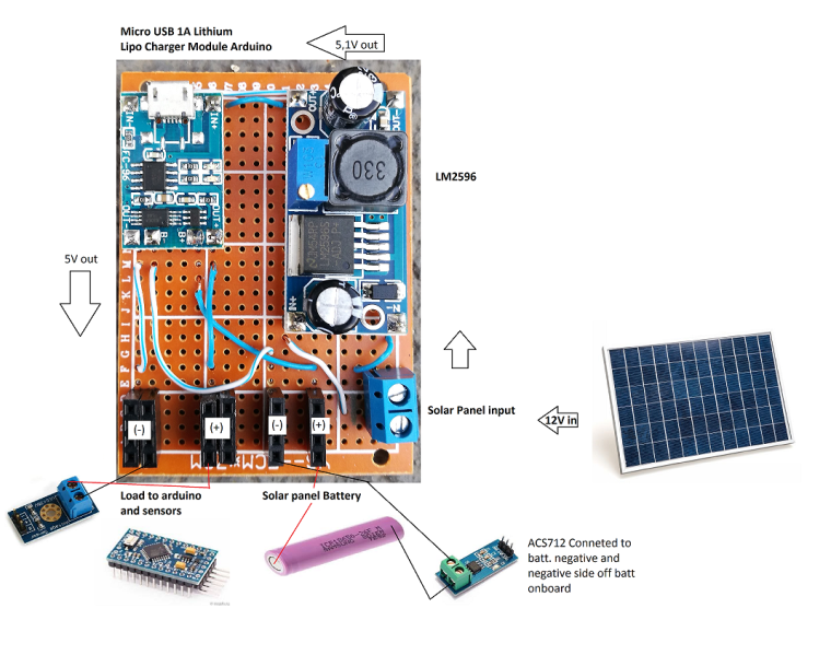
Here's the way i'm powering things up.
I don't have a solar charge since last summer we had a big fire on my island and all my arduino and sensors that were outside were all damage from the fire and hot temperatures. So to fiz this problem i'm using the LM2596 to reduce the 12V from the solar panels to 5.5V so that the lipo charger can work. Above the 5v this charger will get damage.
Some data from this charger:
LED: Red = Charging, Green = Complete
Input Voltage: 4.5 to 5.5V
Battery Max Charge Voltage: 4.2V - charges a 1S Lithium Ion Polymer Battery
This outputs a 4.2V on the load and batt connections.
My arduino and sensors are connected to the load pins from the lipo charger as you can see on the picture.
Thanks for your replay and help.
This is my new code for this sensor and reajusted to library 2.1.1
/**
 * The MySensors Arduino library handles the wireless radio link and protocol
 * between your home built sensors/actuators and HA controller of choice.
 * The sensors forms a self healing radio network with optional repeaters. Each
 * repeater and gateway builds a routing tables in EEPROM which keeps track of the
 * network topology allowing messages to be routed to nodes.
 *
 * Created by Henrik Ekblad <henrik.ekblad@mysensors.org>
 * Copyright (C) 2013-2015 Sensnology AB
 * Full contributor list: https://github.com/mysensors/Arduino/graphs/contributors
 *
 * Documentation: http://www.mysensors.org
 * Support Forum: http://forum.mysensors.org
 *
 * This program is free software; you can redistribute it and/or
 * modify it under the terms of the GNU General Public License
 * version 2 as published by the Free Software Foundation.
 *
 *******************************
 *
 * REVISION HISTORY
 * Version 1.0 - epierre
 * Contribution: bulldoglowell, gizmocuz
 *
 * DESCRIPTION
 * Connect sensor ML8511 / Arduino:
 *
 *  3.3V = 3.3V
 *  OUT = A0
 *  GND = GND
 *  EN = 3.3V
 *  Arduino 3.3V = Arduino A1
 *
 * License: Attribution-NonCommercial-ShareAlike 3.0 Unported (CC BY-NC-SA 3.0)
 */

// Enable debug prints
#define MY_DEBUG

// Enable and select radio type attached
#define MY_RADIO_NRF24
//#define MY_RADIO_RFM69
//#define MY_RS485

#include <SPI.h>
#include <MySensors.h>
#include <SPI.h>

//Hardware pin definitions
int REF_3V3 = A1;
int UVOUT = A0;

#define CHILD_ID_UV 0

unsigned long SLEEP_TIME = 30*1000; // Sleep time between reads (in milliseconds)

MyMessage uvMsg(CHILD_ID_UV, V_UV);

float lastUV = -1;
unsigned long lastSend =0;

void presentation()
{
  // Send the sketch version information to the gateway and Controller
  sendSketchInfo("UV Sensor", "3.0");

  // Register all sensors to gateway (they will be created as child devices)
  present(CHILD_ID_UV, S_UV, "ML8511_UV");
}

void setup()
{
  //gw.begin(NULL, 9, true);
  pinMode(UVOUT, INPUT);
  pinMode(REF_3V3, INPUT);
}

void loop()
{
  int uvLevel = averageAnalogRead(UVOUT);
  int refLevel = averageAnalogRead(REF_3V3);
  unsigned long currentTime = millis();

  //Use the 3.3V power pin as a reference to get a very accurate output value from sensor
  float outputVoltage = 3.3 / refLevel * uvLevel;

  //float outputVoltage = 5.0 * uvLevel/1024;
  float uvIntensity = mapfloat(outputVoltage, 0.99, 2.8, 0.0, 15.0);          //Convert the voltage to a UV intensity level

  Serial.print("output: ");
  Serial.print(refLevel);

  Serial.print("ML8511 output: ");
  Serial.print(uvLevel);

  Serial.print(" / ML8511 voltage: ");
  Serial.print(outputVoltage);

  Serial.print(" / UV Intensity (mW/cm^2): ");
  Serial.print(uvIntensity);

  Serial.println();

  if ((uvIntensity != lastUV)||(currentTime-lastSend >= 5*60*1000))
  {
      lastSend=currentTime;
      send(uvMsg.set(uvIntensity,2));
      lastUV = uvIntensity;
  }
  delay(100);
}

//Takes an average of readings on a given pin
//Returns the average
int averageAnalogRead(int pinToRead)
{
  byte numberOfReadings = 8;
  unsigned int runningValue = 0;

  for(int x = 0 ; x < numberOfReadings ; x++)
    runningValue += analogRead(pinToRead);
  runningValue /= numberOfReadings;

  return(runningValue);
}

//The Arduino Map function but for floats
//From: http://forum.arduino.cc/index.php?topic=3922.0
float mapfloat(float x, float in_min, float in_max, float out_min, float out_max)
{
  return (x - in_min) * (out_max - out_min) / (in_max - in_min) + out_min;
}```I'm working again on this system but i'm having some troubles... The code has you caan see i have already adapted it to version 2.1.1 Now on the hardware i'm building i have this:
My problem is that when i have the system online the values i'm getting are not right. For the battery voltage i get 5,5v when i believe i should be getting 3,7v or 4,1v maximum.
The charge and load are always on 0,2A or 0,0A
I have the acs712 connected to the negative side off the battery and the Voltage sensor connected to the negative and positive side off the battery.
What i'm i doing rong here ????
Hi. i have been working on this solar code and have made the changes to work over mysensors 2.1.1
I'm now triyng to add a line code to monitor the voltage from the solar panels. Can anyone give me a help on this?
I want to now the voltage watts or kws produce over my pannels. The idea is to have domoticz monitoring all data produce over the solar pannel.
Thanks
/*Sketch for a MySensor node to monitor a 12v battery with a solar panel for charging
 * The node monitors battery voltage,current into and out of the battery, ambient temperature and battery temperature.
 * 2 x DS18b20 dallas temperature ic's their data pins connected to arduino digital pin 3
 * 1 x ACS712 current sensor module connected to  arduino analog pin A4
 * 1 x 25v voltage sensor module connected to arduino analog pin A0
 * 1 x nRF24L01+  2.4ghz tranceiver connected as per the MySensors web site.
 * 1 x LED connected via a 330 ohm resistor to pin 6
 * 1 x push button connected to pin 5
 */

// Enable debug prints to serial monitor
#define MY_DEBUG

// Enable and select radio type attached
#define MY_RADIO_NRF24
//#define MY_RADIO_RFM69

// Enable repeater functionality for this node
#define MY_REPEATER_FEATURE

#include <MySensors.h>
#include <SPI.h>
#include <OneWire.h>
#include <DallasTemperature.h>

#define ONE_WIRE_BUS 3                            // Ds18b20 data wire is connected to digital pin 3 on the Arduino
#define ID_S_TEMP_A 0                             // First temp device
#define ID_S_TEMP_B 1                             // Second temp device
#define ID_S_MULTIMETERV 3                        // Multimeter device for voltage measurement
#define ID_S_MULTIMETERC 4                        // Multimeter device for positive current measurement
#define ID_S_MULTIMETERC1 5                       // Multimeter device for negative current measurement
#define NUM_SAMPLES 10                            // number of analog voltage samples to take per reading

int ledPin = 6;                                   // the pin for the LED
int buttonPin = 5;                                // the input pin for offset pushbutton
int buttonState = 0;                              // variable for reading the pin status
unsigned long SLEEP_TIME = 30000;                 // Sleep time between reads (in milliseconds)
int lastmilli = 25000;                            // set to an arbitary number outside of expected current sensor range to ensure a change when first run
float sensitivity = 66 ;                          // change this to 185 for ACS712-5 or to 100 for ACS712-20A or to 66 for ACS712-30A
int VQ = 0;                                       // Placeholder for quiescent voltage calculations
int ACSPin = A4;                                  // Analog pin number the ACS712 data pin connects to
float lastTemperature[2];                         // Array to hold the last temp readings sent to gateway, only send new data if different
int sum = 0;                                      // sum of voltage samples taken
unsigned char sample_count = 0;                   // current sample number
int lastVoltage = 30000;                          // set to an arbitary number outside of expected voltage sensor range to ensure a change when first run
int voltagePin = A0;                              // analog pin voltage sensor or voltage divider is connected to
int voltSenseMax = 25000;                         // set to the maximum input voltage in millivolts of your voltage divider input
OneWire oneWire(ONE_WIRE_BUS);                    // Setup a oneWire instance to communicate with any OneWire devices (not just Maxim/Dallas temperature ICs)
DallasTemperature sensors(&oneWire);              // Pass our oneWire reference to Dallas Temperature.

// ------ Initialize  messages ------- //
MyMessage msg(0,V_TEMP);
MyMessage msg_S_MULTIMETERv(ID_S_MULTIMETERV,V_VOLTAGE);
MyMessage msg_S_MULTIMETERc(ID_S_MULTIMETERC,V_CURRENT);
MyMessage msg_S_MULTIMETERc1(ID_S_MULTIMETERC1,V_CURRENT);

void presentation()
{
  // Send the sketch version information to the gateway
  sendSketchInfo("Battery Status Sensor", "2.1.1");

  // Register all sensors to gw (they will be created as child devices)
  present(ID_S_TEMP_A, S_TEMP);
  present(ID_S_TEMP_B, S_TEMP);
  present(ID_S_MULTIMETERV,V_VOLTAGE);
  present(ID_S_MULTIMETERC,V_CURRENT);
  present(ID_S_MULTIMETERC1,V_CURRENT);
}

void setup()
{
  sensors.begin();                                      // Start up the onewire library
  pinMode(buttonPin, INPUT_PULLUP);                     // Set buttonPin as input and turn on internal pull up resistor
  pinMode(ledPin, OUTPUT);                              // Set ledPin as output
  digitalWrite(ledPin, LOW);                            // Make sure ledPin is off

  // ------ load offset for current sensor
  int validCheck = loadState(0);
  if (validCheck == 120)                                // check to see if valid data exists
  {
    VQ = loadState(1);                                  // Load count offset into VQ
    //Serial.print(" positive VQ offset loaded..."); Serial.println(VQ);
  }
  else if (validCheck == 125)
  {
    VQ = -abs(loadState(1));
    //Serial.print(" negative VQ offset loaded..."); Serial.println(VQ);
  }
  else
  {
    //Serial.println("VQ offset not set");
  }
  delay(500);
}

void loop()
{
  buttonState = digitalRead(buttonPin);
  //Serial.print("buttonstate..."); Serial.println(buttonState);
  if (buttonState == LOW)
  {
    VQ = determineVQ(ACSPin);                           // Returns the offset count needed to show zero with no load
    if (VQ >= 0 && VQ < 255)
    {                                                   // check for valid data. VQ is positive number
      saveState(0, 120);                                // Store 120 value  in eeprom position 0. use this to check for valid data at boot
      saveState(1, VQ);                                 // Store offset count in eeprom. in case of re-boot
    }
    else if (VQ < 0 && VQ > -255)                       // VQ is a negative number. negatives cannot be stored in eeprom
    {
      saveState(0, 125);                                // Store 125 value  in eeprom position 0. use this to check for valid data at boot
      saveState(1, abs(VQ));                            // convert VQ to positive and  Store offset count in eeprom. in case of re-boot
    }
  }

//-------------------------------------------- Start voltage readings ----------------------------------------------------

  sample_count = 0;
  sum = 0;
  while (sample_count < NUM_SAMPLES)                     // take a number of voltage samples
  {
    sum += analogRead(voltagePin);
    sample_count++;
    delay(10);
  }

  //Serial.print("sum count..."); Serial.println((sum / NUM_SAMPLES));        // print the count result. will be between 0 and 1023
  int voltageI = map(sum/NUM_SAMPLES,0,1023,0,voltSenseMax);                  // map the reading and get our result in millivolts
  //Serial.print("mapped volts..."); Serial.println(voltageI / 1000.0, 1);    // convert millivolts back to volts and print. the 1 at the end determines how many decimal places to show

  if ( voltageI != lastVoltage)                                               // check if we have a new value. only send data if it is different
  {
    send(msg_S_MULTIMETERv.set(voltageI / 1000.0, 1));                        // voltagel is in millivolts so we divide by 1000 to convert back to volts and send voltage message to gateway with 1 decimal place
    lastVoltage = voltageI;                                                   // copy the current voltage reading for testing on the next loop
  }

//---------------------------------------- Start Current readings ---------------------------------------------------------

  int milli = readCurrent(ACSPin);                                            // take a reading from the ACS712 and send to the readcurrent function
  //Serial.print("Milliamps..."); Serial.println(milli);                      // print the value (in milliamps) returned
  if ( milli != lastmilli)                                                    // check if value has changed
  {
    if ( milli > 0)                                                           // Battery is charging
    {
      send(msg_S_MULTIMETERc.set(milli/1000.0, 1));                           // Send new data to charging amp device
      send(msg_S_MULTIMETERc1.set(0));                                        // set the dis-charging amp device to zero
      lastmilli =  milli;
    }
    else if (milli < 0)                                                       // Battery is discharging
    {
      send(msg_S_MULTIMETERc.set(0));                                         // set the charging amp device to zero
      send(msg_S_MULTIMETERc1.set(abs(milli)/1000.0, 1));                     //  use abs(milli) to Send a positive number  to dis-charging amp device
      lastmilli =  milli;
    }
    else                                                                      // No current flowing, set both to zero
    {
      send(msg_S_MULTIMETERc.set(0));
      send(msg_S_MULTIMETERc1.set(0));
      lastmilli =  milli;
    }
  }

//--------------------------------------- Temperature readings start ------------------------------------------------------------

  Serial.println(" Requesting temperatures...");
  // Fetch temperatures from Dallas sensors
  sensors.requestTemperatures();                              // call sensors.requestTemperatures() to issue a global temperature request to all devices on the bus

  // ------- query conversion time and sleep until conversion completed ------
  int16_t conversionTime = sensors.millisToWaitForConversion(sensors.getResolution());
  sleep(conversionTime);

  for (int i=0; i<2; i++)
  {
    //Serial.print("Temperature for Device: ");Serial.print(i);Serial.print(" is: ");
    //Serial.println(sensors.getTempCByIndex(i)); // Why "byIndex"?
    // You can have more than one IC on the same bus.
    // 0 refers to the first IC on the wire

    float temperature = static_cast<float>(static_cast<int>((sensors.getTempCByIndex(i)) * 10.)) / 10.;    // Fetch and round temperature to one decimal in celcius
    if (lastTemperature[i] != temperature)                                                                 // check for a changed temperature reading
    {
      send(msg.setSensor(i).set(temperature,1));                                                           // Send in the new temperature
      lastTemperature[i]=temperature;                                                                      // Save new temperatures for next compare
    }
  }
  sleep(SLEEP_TIME);
}

/*-------------- Function to get the offset required for ACS712 to show zero with no current flowing -----------------*/
int determineVQ(int PIN)
{
  digitalWrite(ledPin, HIGH);                                             // Turn on LED to indicate offset being calculated
  delay(500);                                                             // Delay to hold LED on
  digitalWrite(ledPin, LOW);                                              // Turn off LED
  delay(150);                                                             // Delay to let readings stabilise
  //Serial.print("estimating avg. quiscent voltage:");
  long acsCount = 0;
  for (int i=0; i<5000; i++)                                              // read 5000 samples to stabilise value
  {
    acsCount += analogRead(PIN);                                          // read the count value between 0 and 1023 and add it to acsCount
    delay(1);
  }
  acsCount /= 5000;                                                       // acsCount now eaquals the average of the 5000 readings taken
  //Serial.print(map(acsCount, 0, 1023, 0, 5000));Serial.println(" mV");  // Print the avg in millivolts
  //Serial.print("acsCount:");Serial.println(acsCount);                   // Print the actual count value
  return int(acsCount - 512);                                             // return the count difference. 512 is the count for 2.5v which is what the reading should be with no current flow

}

/*--------------- Function to read current flowing ------------------*/
int readCurrent(int PIN)
{
 int count = 0;
 for (int i=0; i<5; i++)                                                  // read 5 analog count samples to stabilise value
  {
   count += analogRead(PIN) - VQ;                                         // subtract the offset count VQ to improve accuracy
   delay(1);
  //Serial.print("raw count..."); Serial.println(count);
  }

/* Notes on the conversion below
 *  .00488 is the volt value per count of the arduino adc. The analog pin measures from 0 to 5 volt and then assigns the result to
 *  a count from 0 to 1023, thats 1024 counts including zero. If we devide 5v by 1024 we get .oo488 volts for each count.
 *
 *  The (count/5) just gets us the average of our 5 count samples.
 *
 *  So after the first part of the equation  (.00488 * (count/5) is complete we have converted our count reading into volts.
 *
 *  The ACS712 can measure current flow in both directions so it outputs a voltage of  2.5v as it's center point (when no current is flowing).
 *  To allow for this offset we must subtract the 2.5v to center our voltage reading.
 *
 * Thats what the next part does (.00488 * (count/5)) - 2.5) After this is complete we are left with either a negative or  positive voltage
 * reading or a reading of zero for no current flow.
 *
 * NOTE: While the ACS712 is a 5v device it does not use the full 0 to 5v for it's output. The datasheet shows the 20A version has a sensitivity of
 *  100mv per amp, so if we multiply 100mv by 20 we get 2v.  That means the 20A ACS712 has an output range from .5v to 4.5v.
 *
 * So to convert our reading in volts to a reading in amps we need to add the last part ((.00488 * (count/5)) - 2.5)/(sensitivity/1000).
 * The variable sensitivity is defined at the begining of the sketch and holds the ACS712 sensitvity amount, it is stored in millivolts.
 * That is 66mv for the 30amp,  100mv for the 20amp and 185mv for the 5amp. As sensitivity is in millivolts we need to devide it by 1000
 * to convert it back to volts so we can use it in the equation.
 *
 * Now we have our Amps value stored in the float amps. Integers are much easier to work with when checking for zero so we multiply by 1000
 * to convert it to milliamps and return it as an integer.
*/

//Serial.print("VQ = ..."); Serial.println(VQ);
//Serial.print("current count..."); Serial.println(count/5);
//Serial.print("map  milliamps..."); Serial.println(map((count/5), 102, 922, -20000, 20000));
  float amps = ((.00488 * (count/5)) - 2.5) / (sensitivity/1000);
//Serial.print("float amps..."); Serial.println(amps, 1);
  return int (amps * 1000);                                         // convert to milliamps and return as an integer
}```@sundberg84 Hi here's the code i'm using
// Enable debug prints to serial monitor
#define MY_DEBUG

// Enable and select radio type attached
#define MY_RADIO_NRF24
//#define MY_RADIO_RFM69

#define MY_NODE_ID 7

#include <MySensors.h>


#define UV_SENSOR_ANALOG_PIN 0

#define CHILD_ID_UV 0

unsigned long SLEEP_TIME = 30*1000; // Sleep time between reads (in milliseconds)

MyMessage uvMsg(CHILD_ID_UV, V_UV);

unsigned long lastSend =0;
float uvIndex;
float lastUV = -1;
uint16_t uvIndexValue [12] = { 50, 227, 318, 408, 503, 606, 696, 795, 881, 976, 1079, 1170};


void presentation()
{
    // Send the sketch version information to the gateway and Controller
    sendSketchInfo("UV Sensor", "1.2");

    // Register all sensors to gateway (they will be created as child devices)
    present(CHILD_ID_UV, S_UV);
}

void loop()
{
    unsigned long currentTime = millis();

    uint16_t uv = analogRead(UV_SENSOR_ANALOG_PIN);// Get UV value
    if (uv>1170) {
        uv=1170;
    }

    //Serial.print("UV Analog reading: ");
    //Serial.println(uv);

    int i;
    for (i = 0; i < 12; i++) {
        if (uv <= uvIndexValue[i]) {
            uvIndex = i;
            break;
        }
    }

    //calculate 1 decimal if possible
    if (i>0) {
        float vRange=uvIndexValue[i]-uvIndexValue[i-1];
        float vCalc=uv-uvIndexValue[i-1];
        uvIndex+=(1.0/vRange)*vCalc-1.0;
    }

    //Serial.print("UVI: ");
    //Serial.println(uvIndex,2);

    //Send value to gateway if changed, or at least every 5 minutes
    if ((uvIndex != lastUV)||(currentTime-lastSend >= 5UL*60UL*1000UL)) {
        lastSend=currentTime;
        send(uvMsg.set(uvIndex,2));
        lastUV = uvIndex;
    }

    //sleep(SLEEP_TIME);
}```@sundberg84 Here's my debug data with sensor connecte to pin A0:
Starting sensor (RNNNA-, 2.0.0)
TSM:INIT
TSM:RADIO:OK
TSP:ASSIGNID:OK (ID=7)
TSM:FPAR
TSP:MSG:SEND 7-7-255-255 s=255,c=3,t=7,pt=0,l=0,sg=0,ft=0,st=bc:
TSP:MSG:READ 0-0-7 s=255,c=3,t=8,pt=1,l=1,sg=0:0
TSP:MSG:FPAR RES (ID=0, dist=0)
TSP:MSG:PAR OK (ID=0, dist=1)
TSM:FPAR:OK
TSM:ID
TSM:CHKID:OK (ID=7)
TSM:UPL
TSP:PING:SEND (dest=0)
TSP:MSG:SEND 7-7-0-0 s=255,c=3,t=24,pt=1,l=1,sg=0,ft=0,st=ok:1
TSP:MSG:READ 0-0-7 s=255,c=3,t=25,pt=1,l=1,sg=0:1
TSP:MSG:PONG RECV (hops=1)
TSP:CHKUPL:OK
TSM:UPL:OK
TSM:READY
TSP:MSG:SEND 7-7-0-0 s=255,c=3,t=15,pt=6,l=2,sg=0,ft=0,st=ok:0100
!TSP:MSG:SEND 7-7-0-0 s=255,c=0,t=17,pt=0,l=5,sg=0,ft=0,st=fail:2.0.0
TSP:MSG:SEND 7-7-0-0 s=255,c=3,t=6,pt=1,l=1,sg=0,ft=1,st=ok:0
TSP:MSG:READ 0-0-7 s=255,c=3,t=6,pt=0,l=1,sg=0:M
TSP:MSG:SEND 7-7-0-0 s=255,c=3,t=11,pt=0,l=9,sg=0,ft=0,st=ok:UV Sensor
TSP:MSG:SEND 7-7-0-0 s=255,c=3,t=12,pt=0,l=3,sg=0,ft=0,st=ok:1.2
TSP:MSG:SEND 7-7-0-0 s=0,c=0,t=11,pt=0,l=0,sg=0,ft=0,st=ok:
Request registration...
TSP:MSG:SEND 7-7-0-0 s=255,c=3,t=26,pt=1,l=1,sg=0,ft=0,st=ok:2
TSP:MSG:READ 0-0-7 s=255,c=3,t=27,pt=1,l=1,sg=0:1
Node registration=1
Init complete, id=7, parent=0, distance=1, registration=1
TSP:MSG:SEND 7-7-0-0 s=0,c=1,t=11,pt=7,l=5,sg=0,ft=0,st=ok:0.00
And here's my debug without sensor connected to arduino A0:
TSM:CHKID:OK (ID=7)
TSM:UPL
TSP:PING:SEND (dest=0)
TSP:MSG:SEND 7-7-0-0 s=255,c=3,t=24,pt=1,l=1,sg=0,ft=0,st=ok:1
TSP:MSG:READ 0-0-7 s=255,c=3,t=25,pt=1,l=1,sg=0:1
TSP:MSG:PONG RECV (hops=1)
TSP:CHKUPL:OK
TSM:UPL:OK
TSM:READY
TSP:MSG:SEND 7-7-0-0 s=0,c=1,t=11,pt=7,l=5,sg=0,ft=0,st=ok:9.17
TSP:MSG:SEND 7-7-0-0 s=0,c=1,t=11,pt=7,l=5,sg=0,ft=0,st=ok:8.75
TSP:MSG:SEND 7-7-0-0 s=0,c=1,t=11,pt=7,l=5,sg=0,ft=0,st=ok:9.46
TSP:MSG:SEND 7-7-0-0 s=0,c=1,t=11,pt=7,l=5,sg=0,ft=0,st=ok:7.90
TSP:MSG:SEND 7-7-0-0 s=0,c=1,t=11,pt=7,l=5,sg=0,ft=0,st=ok:9.46
TSP:MSG:SEND 7-7-0-0 s=0,c=1,t=11,pt=7,l=5,sg=0,ft=0,st=ok:8.07
TSP:MSG:SEND 7-7-0-0 s=0,c=1,t=11,pt=7,l=5,sg=0,ft=0,st=ok:9.46
TSP:MSG:SEND 7-7-0-0 s=0,c=1,t=11,pt=7,l=5,sg=0,ft=0,st=ok:8.79
TSP:MSG:SEND 7-7-0-0 s=0,c=1,t=11,pt=7,l=5,sg=0,ft=0,st=ok:8.84
TSP:MSG:SEND 7-7-0-0 s=0,c=1,t=11,pt=7,l=5,sg=0,ft=0,st=ok:9.38
TSP:MSG:SEND 7-7-0-0 s=0,c=1,t=11,pt=7,l=5,sg=0,ft=0,st=ok:8.49
TSP:MSG:SEND 7-7-0-0 s=0,c=1,t=11,pt=7,l=5,sg=0,ft=0,st=ok:9.46
TSP:MSG:SEND 7-7-0-0 s=0,c=1,t=11,pt=7,l=5,sg=0,ft=0,st=ok:8.25
TSP:MSG:SEND 7-7-0-0 s=0,c=1,t=11,pt=7,l=5,sg=0,ft=0,st=ok:9.46
TSP:MSG:SEND 7-7-0-0 s=0,c=1,t=11,pt=7,l=5,sg=0,ft=0,st=ok:8.80
TSP:MSG:SEND 7-7-0-0 s=0,c=1,t=11,pt=7,l=5,sg=0,ft=0,st=ok:9.36
TSP:MSG:SEND 7-7-0-0 s=0,c=1,t=11,pt=7,l=5,sg=0,ft=0,st=ok:9.11
TSP:MSG:SEND 7-7-0-0 s=0,c=1,t=11,pt=7,l=5,sg=0,ft=0,st=ok:8.61
TSP:MSG:SEND 7-7-0-0 s=0,c=1,t=11,pt=7,l=5,sg=0,ft=0,st=ok:9.46
TSP:MSG:SEND 7-7-0-0 s=0,c=1,t=11,pt=7,l=5,sg=0,ft=0,st=ok:8.18
TSP:MSG:SEND 7-7-0-0 s=0,c=1,t=11,pt=7,l=5,sg=0,ft=0,st=ok:9.43
TSP:MSG:SEND 7-7-0-0 s=0,c=1,t=11,pt=7,l=5,sg=0,ft=0,st=ok:8.97
TSP:MSG:SEND 7-7-0-0 s=0,c=1,t=11,pt=7,l=5,sg=0,ft=0,st=ok:8.95
TSP:MSG:SEND 7-7-0-0 s=0,c=1,t=11,pt=7,l=5,sg=0,ft=0,st=ok:9.36
TSP:MSG:SEND 7-7-0-0 s=0,c=1,t=11,pt=7,l=5,sg=0,ft=0,st=ok:8.52
TSP:MSG:SEND 7-7-0-0 s=0,c=1,t=11,pt=7,l=5,sg=0,ft=0,st=ok:9.46
TSP:MSG:SEND 7-7-0-0 s=0,c=1,t=11,pt=7,l=5,sg=0,ft=0,st=ok:8.71
TSP:MSG:SEND 7-7-0-0 s=0,c=1,t=11,pt=7,l=5,sg=0,ft=0,st=ok:9.32
TSP:MSG:SEND 7-7-0-0 s=0,c=1,t=11,pt=7,l=5,sg=0,ft=0,st=ok:9.31
TSP:MSG:SEND 7-7-0-0 s=0,c=1,t=11,pt=7,l=5,sg=0,ft=0,st=ok:9.15
TSP:MSG:SEND 7-7-0-0 s=0,c=1,t=11,pt=7,l=5,sg=0,ft=0,st=ok:9.39
Isn't this strange ??
I have already remove the sleep because i'm running this sensor on batteries.