Navigation

    • Register
    • Login
    • OpenHardware.io
    • Categories
    • Recent
    • Tags
    • Popular
    1. Home
    2. nelsonov
    3. Posts
    • Profile
    • Following
    • Followers
    • Topics
    • Posts
    • Best
    • Groups

    Posts made by nelsonov

    • RE: HomeAssitant MySensors plugin Roadmap

      What would be useful is a function that gets called (if it exists) between presentation and loop. Home Assistant requires that some sort of initial value be sent so that it can learn that the device exists. Obviously, these initial values have to be sent after presentation to the gateway.

      What people end up doing is something like this:

      void loop() 
      {
        if (!initialValuesSent) 
        {
          //send initial values
          initialValuesSent = true;
        }
        //rest of loop function
      } 
      

      That if-statement is executed in each iteration of loop() even though it only matters once. It looks ugly, but more importantly, it consumes unnecessary resources.

      posted in Home Assistant
      nelsonov
      nelsonov
    • RE: Multi Button Relay Sketch

      @korttoma Two years later.... I just wanted to say that your sketch is elegant and beautiful. Using arrays is an idea I had as well, but I was just starting to write something when I thought about looking to see if someone had already done it. You saved me days of yelling at the monitor trying work it out for myself. You should consider making a topic out of this script.

      posted in Development
      nelsonov
      nelsonov
    • RE: MySensor on Hass.io - can't get it work

      You might need to take this to the [Home Assistant Forum]
      (https://community.home-assistant.io). Something strange is going on at the OS level. Your kernel is recognizing the USB device, but the OS isn't creating the tty. You can try lsusb just to see if it's still there, but beyond that I'm out of advice. The error you are getting from Home Assistant has awkward wording, but it means that it can't find the serial device.

      posted in Home Assistant
      nelsonov
      nelsonov
    • RE: MySensor on Hass.io - can't get it work

      What do you get from ls -l /dev/tty*?

      posted in Home Assistant
      nelsonov
      nelsonov
    • RE: MySensor on Hass.io - can't get it work

      Are you sure that's the right device? It's /dev/ttyUSB0 that is the source of the error in your output. Maybe the device is something like /dev/ttyAMA0 or /dev/ttyACM0?

      posted in Home Assistant
      nelsonov
      nelsonov
    • RE: Any RFM95 user reports?

      I'm also having trouble with RFM95's. I'm confused about MY_RFM95_IRQ_PIN and MY_RFM95_IRQ_NUM. Does PIN mean the GPIO pin number or the interrupt pin number? I've noticed that the same physical pin has different numbers depending on their use.

      Also, what is the distinction between MY_RFM95_IRQ_PIN andMY_RFM95_IRQ_NUM?

      posted in Hardware
      nelsonov
      nelsonov
    • RE: PingPong without gateway or controller?

      The sketch works using a direct, wired connection (RS485).

      T received - starting test...
      Sending Ping to Ying Node
      2226167 TSF:MSG:SEND,201-201-1-200,s=1,c=1,t=24,pt=5,l=4,sg=0,ft=0,st=OK:2226165
      

      But it does not work with my RFM95's, but that is a completely different topic.

      posted in General Discussion
      nelsonov
      nelsonov
    • RF24:RBR:REG=23,VAL=17

      I'm having a problem similar to what is described in "NRF24 Radio does not link if MY_DEBUG_VERBOSE_RF24 is not defined. #941" https://github.com/mysensors/MySensors/issues/941. My local branch is up to date with the beta development branch (v2.2.0-beta).

      That issue that I referenced seems to deal with data arriving too quickly from the gateway. I am operating without a gateway doing some testing with PingPong, so I'm not sure the problem is the same. (See below for how I'm shutting off attempts to communicate with a Gateway in case it is relevant).

      I'm getting the same error RF24:RBR:REG=23,VAL=17 repeating endlessly, but only on 328P 3.3v 8MHz boards (knock offs from Robotdyn). I've tried two identical boards with the same results. However, the identical sketch runs fine on my 32u4 (Adafruit Feather). The problem, therefore, seems to be hardware specific. I have swapped radios back and forth and the trouble remains on the 328 even when using the radio that works on the 32u4.

      I have an identical 328p and NRF24 (from the same shipment) up and running under 2.1.1. Something seems to have crept in with the changes in the new beta. What can I do to help debug?

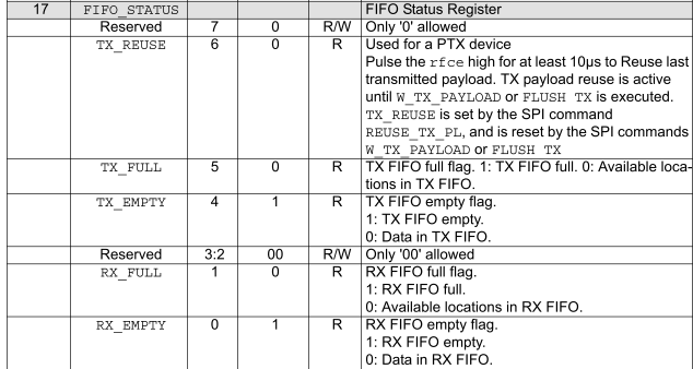
      Assuming that "REG=23" refers to decimal register 23, then looking up the register as hex 17 in the specification, I find this:

      0_1512018083126_Capture.PNG

      If I'm reading the chart right (assuming I'm even in the right place) then it looks like the NRF24 is reporting RX_EMPTY and TX_EMPTY.

      The radios are all NRF24L01+ from Makerfire.

      Shutting off Gateway communication:

      #define MY_TRANSPORT_WAIT_READY_MS 3000
      #define   MY_TRANSPORT_UPLINK_CHECK_DISABLED  //Don't check for uplink
      #define   MY_NODE_ID 199  //Fallback NodeId
      #define   MY_PARENT_NODE_ID  1
      #define   MY_PARENT_NODE_IS_STATIC
      
      posted in Development
      nelsonov
      nelsonov
    • RE: PingPong without gateway or controller?

      Based on what @gohan posted, I searched for 'without gateway' and found several useful posts. Sometimes all it takes is knowing how to ask the question.

      posted in General Discussion
      nelsonov
      nelsonov
    • RE: PingPong without gateway or controller?

      @gohan confirmed one of my guesses. I made some further guesses as well. I hard coded a node ID, disabled the uplink check, hard coded a parent ID and defined it as static. All of this seems to have gotten the node to be independent.

      One of the consequences of my modifications is that entering "0" or "1" in the terminal no longer has any real effect. Below is the output, including the results of me entering "T" from the serial monitor at the end.

       __  __       ____
      |  \/  |_   _/ ___|  ___ _ __  ___  ___  _ __ ___
      | |\/| | | | \___ \ / _ \ `_ \/ __|/ _ \| `__/ __|
      | |  | | |_| |___| |  __/ | | \__ \  _  | |  \__ \
      |_|  |_|\__, |____/ \___|_| |_|___/\___/|_|  |___/
              |___/                      2.2.0-rc.1
      
      18 MCO:BGN:INIT NODE,CP=RLNNA---,VER=2.2.0-rc.1
      28 TSM:INIT
      28 TSF:WUR:MS=0
      47 TSM:INIT:TSP OK
      49 TSM:INIT:STATID=201
      51 TSF:SID:OK,ID=201
      53 TSM:FPAR
      53 TSM:FPAR:STATP=1
      55 TSM:ID
      57 TSM:ID:OK
      59 TSM:UPL:DISABLED
      61 TSM:READY:ID=201,PAR=1,DIS=1
      15376 !TSF:MSG:SEND,201-201-1-0,s=255,c=3,t=15,pt=6,l=2,sg=0,ft=0,st=NACK:0100
      32694 !TSF:MSG:SEND,201-201-1-0,s=255,c=0,t=17,pt=0,l=10,sg=0,ft=1,st=NACK:2.2.0-rc.1
      48015 !TSF:MSG:SEND,201-201-1-0,s=255,c=3,t=6,pt=1,l=1,sg=0,ft=2,st=NACK:1
      65335 !TSF:MSG:SEND,201-201-1-0,s=1,c=0,t=23,pt=0,l=0,sg=0,ft=3,st=NACK:
      80656 !TSF:MSG:SEND,201-201-1-0,s=255,c=3,t=11,pt=0,l=9,sg=0,ft=4,st=NACK:Yang Node
      96006 !TSF:MSG:SEND,201-201-1-0,s=255,c=3,t=12,pt=0,l=4,sg=0,ft=5,st=NACK:v1.0
      
      Yang NodeReady.
      96014 MCO:REG:REQ
      111357 !TSF:MSG:SEND,201-201-1-0,s=255,c=3,t=26,pt=1,l=1,sg=0,ft=6,st=NACK:2
      111366 !TSM:READY:UPL FAIL,STATP
      128645 !TSF:MSG:SEND,201-201-1-0,s=255,c=3,t=26,pt=1,l=1,sg=0,ft=0,st=NACK:2
      145936 !TSF:MSG:SEND,201-201-1-0,s=255,c=3,t=26,pt=1,l=1,sg=0,ft=1,st=NACK:2
      163254 !TSF:MSG:SEND,201-201-1-0,s=255,c=3,t=26,pt=1,l=1,sg=0,ft=2,st=NACK:2
      165263 MCO:BGN:STP
      Setting node id to: 201.
      ***Please restart the node for changes to take effect.
      165267 MCO:BGN:INIT OK,TSP=1
      T received - starting test...
      Sending Ping to Ying Node
      289431 !TSF:MSG:SEND,201-201-1-200,s=1,c=1,t=24,pt=5,l=4,sg=0,ft=3,st=NACK:274122
      

      Here's is my hacked, diced and sliced version of the sketch. As noted, nothing is changed below void presentation()

      /***
       *  This is a simple sketch used to demenstrate and test node-to-node MySensor's communication.
       *  To use this sketch, assemble MySensors nodes - they need nothing more than a radio
       *  1.  Flash each node with the same sketch, open the console and type either 0 or 1 to the respective nodes to set thei ID
       *  2.  You only need to set the node id once, and restart the nodes
       *  3.  To being a ping-pong test, simply type T in the console for one of the nodes.
       *
       *  2015-05-25 Bruce Lacey v1.0
       */
      
      //The Node ID's are hard coded in this sketch, so the option described in #1 above
      //of specifying 0 or 1 no longer works.  Each node will need to be flahed with the
      //correct #define for eith NODE_YING or NODE_YANG
      
      //Which node is this?
      //#define NODE_YING
      #define NODE_YANG
      
      // Define two generic nodes with a single child
      #define YING 200
      #define YANG 201
      #define CHILD 1
      
      // Enable debug prints to serial monitor
      #define MY_DEBUG
      //#define   MY_SPECIAL_DEBUG
      #define   MY_TRANSPORT_UPLINK_CHECK_DISABLED  //Don't check for uplink
      #define   MY_NODE_ID 199  //Fallback NodeId
      
      //We don't care about a parent, but this satisfies various demands
      //We hard code a parent ID of 1 and say that it's static
      //so that the system won't check for one
      #define   MY_PARENT_NODE_ID  1
      #define   MY_PARENT_NODE_IS_STATIC
      
      //Override the fallback NodeId
      #ifdef NODE_YING
      #define MY_NODE_ID YING
      #endif
      #ifdef NODE_YANG
      #define MY_NODE_ID YANG
      #endif
      
      // Enable and select radio type attached
      //#define MY_RADIO_NRF24
      //#define MY_RADIO_NRF5_ESB
      //#define MY_RADIO_RFM69
      //#define MY_RADIO_RFM95
      
      //RFM95 with various trial settings
      #define   MY_RFM95_FREQUENCY RFM95_915MHZ
      #define   MY_RFM95_MODEM_CONFIGRUATION RFM95_BW125CR45SF128 
      #define   MY_RFM95_ATC_MODE_DISABLED
      #define   MY_RFM95_MAX_POWER_LEVEL_DBM 20
      
      //My nodes are different hardware with different pinouts
      #ifdef NODE_YING
      #define   RFM95_IRQ_PIN     5  // library 2.1.1 = GPIO Pin 9
      #define   RFM95_RST_PIN     5  // library 2.1.1
      #define   RFM95_SPI_CS      6  // library 2.1.1
      #define   MY_RFM95_IRQ_PIN  5  // library 2.2 beta = GPIO
      #define   MY_RFM95_RST_PIN  5  // library 2.2 beta
      #define   MY_RFM95_CS_PIN   6  // library 2.2 beta
      #endif
      #ifdef NODE_YANG
      #define   RFM95_IRQ_PIN     6  // library 2.1.1
      #define   RFM95_RST_PIN     9  // library 2.1.1
      #define   RFM95_SPI_CS     10  // library 2.1.1
      #define   MY_RFM95_IRQ_PIN  6  // library 2.2 beta = GPIO Pin 6
      #define   MY_RFM95_RST_PIN  9  // library 2.2 beta
      #define   MY_RFM95_CS_PIN  10  // library 2.2 beta
      #endif
      
      #define   MY_RADIO_RFM95
      //#define   MY_DEBUG_VERBOSE_RFM95
      
      #include <MySensors.h>
      #include "MYSLog.h"
      
      #define VSN "v1.0"
      
      MyMessage mPing(CHILD, V_VAR1);   //Ping message
      MyMessage mPong(CHILD, V_VAR2);   //Pong message
      
      void setup()
      {
      #ifdef NODE_YING
        setNodeId(YING);
      #endif
      #ifdef NODE_YANG
        setNodeId(YANG);
      #endif
      }
      
      //////////////////////////////////////////////
      //No changes have been made below this point
      //////////////////////////////////////////////
      
      void presentation()
      {
      	present(CHILD, S_CUSTOM);  //
      
      	sendSketchInfo( nodeTypeAsCharRepresentation( getNodeId() ), VSN );
      	LOG(F("\n%sReady.\n"), nodeTypeAsCharRepresentation(getNodeId()));
      }
      
      void loop()
      {
      
      	// Interactive command and control
      	// Entering a number from 0 or 1 will write the node 200 (YING) or 201 (YANG) to EEPROM
      	// Entering T on either node will initiatve a ping-pong test.
      	if (Serial.available()) {
      		byte inChar = Serial.read();
      		uint8_t node = getNodeId();
      
      		// Manual Test Mode
      		if (inChar == 'T' || inChar == 't') {
      			LOG(F("T received - starting test...\n"));
      			MyMessage msg = mPong;
      			msg.sender = (node == YING ? YANG : YING);
      			sendPingOrPongResponse( msg );
      		} else if (inChar == '0' or inChar == '1') {
      			byte nodeID = 200 + (inChar - '0');
      			setNodeId(nodeID);
      		} else {
      			LOG("Invalid input\n");
      		}
      	}
      }
      
      void receive(const MyMessage &message)
      {
      
      	LOG(F("Received %s from %s\n"), msgTypeAsCharRepresentation((mysensor_data)message.type),
      	    nodeTypeAsCharRepresentation(message.sender));
      
      	delay(250);
      	sendPingOrPongResponse( message );
      }
      
      void sendPingOrPongResponse( MyMessage msg )
      {
      
      	MyMessage response = (msg.type == V_VAR1 ? mPong : mPing);
      
      	LOG(F("Sending %s to %s\n"), msgTypeAsCharRepresentation( (mysensor_data)response.type ),
      	    nodeTypeAsCharRepresentation(msg.sender));
      
      	// Set payload to current time in millis to ensure each message is unique
      	response.set( (uint32_t)millis() );
      	response.setDestination(msg.sender);
      	send(response);
      }
      
      void setNodeId(byte nodeID)
      {
      	LOG(F("Setting node id to: %i.\n***Please restart the node for changes to take effect.\n"), nodeID);
      	hwWriteConfig(EEPROM_NODE_ID_ADDRESS, (byte)nodeID);
      }
      
      const char * msgTypeAsCharRepresentation( mysensor_data mType )
      {
      	return mType == V_VAR1 ? "Ping" : "Pong";
      }
      
      const char * nodeTypeAsCharRepresentation( uint8_t node )
      {
      	return node == YING ? "Ying Node" : "Yang Node";
      }
      
      posted in General Discussion
      nelsonov
      nelsonov
    • PingPong without gateway or controller?

      I am trying to test RFM95 radios. So far I can not get any communication between them. I would like to be able to test without having to worry about a gateway or controller. I just want to get communication of some kind between the two nodes. I have tried the Example sketch PingPongSensor, but it is going through the process of trying to communicate upstream:

       __  __       ____
      |  \/  |_   _/ ___|  ___ _ __  ___  ___  _ __ ___
      | |\/| | | | \___ \ / _ \ `_ \/ __|/ _ \| `__/ __|
      | |  | | |_| |___| |  __/ | | \__ \  _  | |  \__ \
      |_|  |_|\__, |____/ \___|_| |_|___/\___/|_|  |___/
              |___/                      2.2.0-rc.1
      
      18 MCO:BGN:INIT NODE,CP=RLNNA---,VER=2.2.0-rc.1
      28 TSM:INIT
      28 TSF:WUR:MS=0
      47 TSM:INIT:TSP OK
      49 TSM:FPAR
      2050 TSF:MSG:SEND,255-255-255-255,s=255,c=3,t=7,pt=0,l=0,sg=0,ft=0,st=OK:
      4059 !TSM:FPAR:NO REPLY
      4061 TSM:FPAR
      6064 TSF:MSG:SEND,255-255-255-255,s=255,c=3,t=7,pt=0,l=0,sg=0,ft=0,st=OK:
      8073 !TSM:FPAR:NO REPLY
      8075 TSM:FPAR
      10078 TSF:MSG:SEND,255-255-255-255,s=255,c=3,t=7,pt=0,l=0,sg=0,ft=0,st=OK:
      12087 !TSM:FPAR:NO REPLY
      12089 TSM:FPAR
      14092 TSF:MSG:SEND,255-255-255-255,s=255,c=3,t=7,pt=0,l=0,sg=0,ft=0,st=OK:
      16101 !TSM:FPAR:FAIL
      16103 TSM:FAIL:CNT=1
      16105 TSM:FAIL:DIS
      16107 TSF:TDI:TSL
      26112 TSM:FAIL:RE-INIT
      26114 TSM:INIT
      26130 TSM:INIT:TSP OK
      26132 TSM:FPAR
      28135 TSF:MSG:SEND,255-255-255-255,s=255,c=3,t=7,pt=0,l=0,sg=0,ft=0,st=OK:
      30144 !TSM:FPAR:NO REPLY
      30146 TSM:FPAR
      32149 TSF:MSG:SEND,255-255-255-255,s=255,c=3,t=7,pt=0,l=0,sg=0,ft=0,st=OK:
      34158 !TSM:FPAR:NO REPLY
      34160 TSM:FPAR
      36163 TSF:MSG:SEND,255-255-255-255,s=255,c=3,t=7,pt=0,l=0,sg=0,ft=0,st=OK:
      38172 !TSM:FPAR:NO REPLY
      38174 TSM:FPAR
      40177 TSF:MSG:SEND,255-255-255-255,s=255,c=3,t=7,pt=0,l=0,sg=0,ft=0,st=OK:
      42186 !TSM:FPAR:FAIL
      

      and so on, endlessly looking for a parent. It never gets to presentation() or loop().

      Is there some easy way to let the test go forward with needing a gateway controller? Since the sketch later sets the nodeId to with 200 or 201 and there is no need to communicate upstream for the simple purpose of a ping, I don't see a need for a gateway or controller to be present for this test.

      posted in General Discussion
      nelsonov
      nelsonov
    • RE: MY_SERIALDEVICE overrides MY_DEBUG_HWSERIAL

      @mfalkvidd I'm quite willing to open a pull request. This will be my first time. Do you want me to create an issue as well? Also what would this be called? Perhaps something like "Alternate Port Debugging"? It's hard to think of something that's 'googlable'.

      posted in Troubleshooting
      nelsonov
      nelsonov
    • RE: MY_SERIALDEVICE overrides MY_DEBUG_HWSERIAL

      @mfalkvidd I'm using an AVR board for my serial gateway. I modified hwDebugPrint in MyHwAVR.cpp with an extra #ifndef to look for MY_DEBUGDEVICE or copy MY_SERIALDEVICE to it. Then all occurrences of MY_SERIALDEVICE were changed to MY_DEBUGDEVICE.

      I added this to my sketch:

      #define MY_DEBUGDEVICE Serial  // Redirect debug to Serial
      

      The result was what I wanted. Controller <-> Gateway configuration went over Serial1 (/dev/ttyS0 on my RPi) and debugging output went to Serial (/dev/ttyACM0 on my RPi). This allows me to easily debug without having to take any special steps with my controller.

      void hwDebugPrint(const char *fmt, ... )
      {
      #ifndef MY_DEBUGDEVICE
      #define MY_DEBUGDEVICE MY_SERIALDEVICE
      #endif
      #ifndef MY_DISABLED_SERIAL
      	char fmtBuffer[MY_SERIAL_OUTPUT_SIZE];
      #ifdef MY_GATEWAY_SERIAL
      	// prepend debug message to be handled correctly by controller (C_INTERNAL, I_LOG_MESSAGE)
      	snprintf_P(fmtBuffer, sizeof(fmtBuffer), PSTR("0;255;%" PRIu8 ";0;%" PRIu8 ";%" PRIu32 " "),
      	           C_INTERNAL, I_LOG_MESSAGE, hwMillis());
      	MY_DEBUGDEVICE.print(fmtBuffer);
      #else
      	// prepend timestamp
      	MY_DEBUGDEVICE.print(hwMillis());
      	MY_DEBUGDEVICE.print(F(" "));
      #endif
      	va_list args;
      	va_start (args, fmt );
      	vsnprintf_P(fmtBuffer, sizeof(fmtBuffer), fmt, args);
      #ifdef MY_GATEWAY_SERIAL
      	// Truncate message if this is gateway node
      	fmtBuffer[sizeof(fmtBuffer) - 2] = '\n';
      	fmtBuffer[sizeof(fmtBuffer) - 1] = '\0';
      #endif
      	va_end (args);
      	MY_DEBUGDEVICE.print(fmtBuffer);
      	MY_DEBUGDEVICE.flush();
      #else
      	(void)fmt;
      #endif
      }
      
      posted in Troubleshooting
      nelsonov
      nelsonov
    • RE: MY_SERIALDEVICE overrides MY_DEBUG_HWSERIAL

      Everything makes much more sense to me now. I found that macro in a discussion on this forum:

      https://forum.mysensors.org/topic/5624/serial-gateway-using-arduino-mega-how-to-set-what-serial-to-use/3

      Now that I have re-read that discussion I understand that I was seeing what I wanted to see.

      Thank you.

      posted in Troubleshooting
      nelsonov
      nelsonov
    • MY_SERIALDEVICE overrides MY_DEBUG_HWSERIAL

      I'm building a serial gateway for my RFM95 radios. I already have a funcitoning ESP8266 gateway for my NRF24 radios. I want to use my device's Serial1 for communication with my controller (RPi running Home Assistant). I would like the debug output to go out my devices USB port, called Serial. So, I would expect to have these two configuration elements:

      #define MY_DEBUG
      #define MY_DEBUG_HWSERIAL Serial
      
      #define MY_GATEWAY_SERIAL
      #define MY_SERIALDEVICE Serial1
      

      However, all output, debug and otherwise, goes out Serial1. If I reverse the configuration, then all output goes out Serial. MY_DEBUG_HWSERIAL does not seem to have any effect.

      The top part of my sketch is included below. Any insight would be appreciated.

      // Enable debug prints to serial monitor
      #define MY_DEBUG
      //Want DEBUG output to Serial (USB Port)
      #define MY_DEBUG_HWSERIAL Serial  // Tried 'Serial' and 'Serial0'
      
      // Enable and select radio type attached
      //#define MY_RADIO_NRF24
      //#define MY_RADIO_RFM69
      // Set LOW transmit power level as default, if you have an amplified NRF-module and
      // power your radio separately with a good regulator you can turn up PA level.
      //#define MY_RF24_PA_LEVEL RF24_PA_LOW
      
      #define   RFM95_IRQ_PIN  6
      #define   RFM95_RST_PIN  9
      #define   RFM95_SPI_CS   10
      #define   MY_RADIO_RFM95
      #define   MY_DEBUG_VERBOSE_RFM95
      
      // Enable serial gateway
      #define MY_GATEWAY_SERIAL
      //Want Gateway <-> Controller communication over Serial1
      #define MY_SERIALDEVICE Serial1
      
      // Define a lower baud rate for Arduino's running on 8 MHz (Arduino Pro Mini 3.3V & SenseBender)
      //#if F_CPU == 8000000L
      #define MY_BAUD_RATE 38400
      //#endif
      
      // Enable inclusion mode
      //#define MY_INCLUSION_MODE_FEATURE
      // Enable Inclusion mode button on gateway
      //#define MY_INCLUSION_BUTTON_FEATURE
      
      // Inverses behavior of inclusion button (if using external pullup)
      //#define MY_INCLUSION_BUTTON_EXTERNAL_PULLUP
      
      // Set inclusion mode duration (in seconds)
      //#define MY_INCLUSION_MODE_DURATION 60
      // Digital pin used for inclusion mode button
      //#define MY_INCLUSION_MODE_BUTTON_PIN  3
      
      // Set blinking period
      //#define MY_DEFAULT_LED_BLINK_PERIOD 300
      
      // Inverses the behavior of leds
      //#define MY_WITH_LEDS_BLINKING_INVERSE
      
      // Flash leds on rx/tx/err
      // Uncomment to override default HW configurations
      //#define MY_DEFAULT_ERR_LED_PIN 4  // Error led pin
      //#define MY_DEFAULT_RX_LED_PIN  6  // Receive led pin
      //#define MY_DEFAULT_TX_LED_PIN  13  // the PCB, on board LED
      
      #include <MySensors.h>```
      posted in Troubleshooting
      nelsonov
      nelsonov