Tested and worked as well. I think this is preferable over the first solution (forward function declaration) as it gives a reference where the functions are defined. Thank you!
perIpI
Posts
-
Help coding: adding functionality relying on MySensors-func/library (saveState/loadState) (c++) -
Help coding: adding functionality relying on MySensors-func/library (saveState/loadState) (c++)@boum said in Help coding: adding functionality relying on MySensors-func/library (saveState/loadState) (c++):
/extern/
Wonderful, that did the trick! Thank you very much!
For namespace/class basically the problem was the same, without "mySensors.h" couldnt find saveState and with "include <mySensors.h>" I had "#error No forward link or gateway feature activated. This means nowhere to send messages! Pretty pointless."
-
Help coding: adding functionality relying on MySensors-func/library (saveState/loadState) (c++)Im using the mySensors functions saveState and loadState to read/write to EEPROM. To facilitate I have written some small functions that do the casting so that I can save uint16_T/float/other by single function call. I would like to organize these functions in a separate file so that I can add this functionality easily to each project. However I struggle to get the structure correct and overcome a compiler warning.
I have collected the functions in .h-file and .cpp-file
Example://mysEeprom.h - declaration of my help-files void save_uint16(uint8_t position, uint16_t value) //mysEeprom.cpp void save_uint16(uint8_t position, uint16_t value) { saveState(position, (uint8_t)value); saveState(position+1, (uint8_t)(value>>8)); } //Project file main.cpp (Radio-declaration etc.) ie #define MY_RADIO_RFM69 #include <mysensors.h> #include <mysEeprom.h> save_uint16(position, value);The compiler responds that saveState "was not declared in this scope" (the saveState is decleared inside MySensors/core/MySensorsCore.h.).
To tell the compiler where to look for saveState I add an #include <mySensors.h>-statement:
//In MysEeprom.h-file
#include "mySensors.h"
This time the compiler seems to believe that I want to includes "double" mySensors.h and responds with:
.pio\libdeps\pro8MHzatmega328\MySensors/mysensors.h:426:2: error: #error No forward link or gateway feature activated. This means nowhere to send messages! Pretty pointless.I had this message earlier when the #include <mySensors.h>-statement was positioned before #define MY_RADIO_RFM69 . Putting MY_RADIO_RFM69-statement before include <mySensors.h> solved it (ie my include-statements are put after definitions, just before declaration of global variables).
I have also experimented organizing my eeprom-functions inside a namespace and a class, but so far have not found a working solution. Help is appreciated, how should this be done, thanks!
-
Problems ethernet GW with ESP8266- NodeMcu V3.4I edited according to Yveaux's work around and its Alive! Connected to the local WIFI OK.
Im not home at the moment so integration with Openhab will have to wait. Thank you all for your help!
-
Problems ethernet GW with ESP8266- NodeMcu V3.4To report back, no progress here either. I've tried to comment out the radio-definition part of the code, and also to move the IRQ-pin between D1 to D4. The nodeMCU will not run and there is no serial output other than the 74880 bootload-message.
I have ordered some NodeMCU version 2 (the ones Ive tried are version 3.4) units as well, but would be surprised if they would be any different.
Is it possible to edit mysensors.h somewhere and enable debugging at some positions just to get a clue of whats going on? I figure whats stopping the boot-up probably happens prior to the normal debugging messages.
An alternative approach could be to go backwards through the library versions (ESP8266 and mysensors) to try and find a working combination?
-
Problems ethernet GW with ESP8266- NodeMcu V3.4@TheoL Thanks for you help!
I should add the "boot-message" only comes when i press the RST. I assumed that the "rst cause:2" was caused by me pressing reset? No continues reboot otherwise.
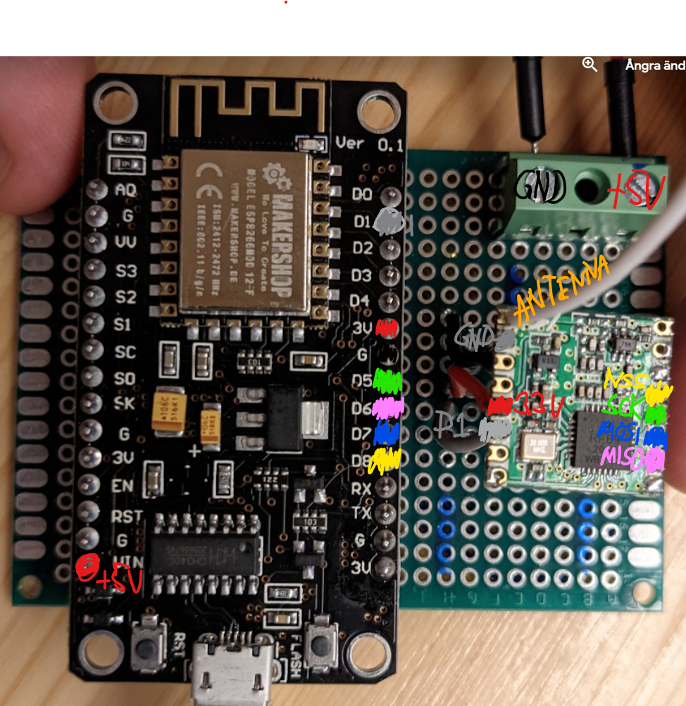
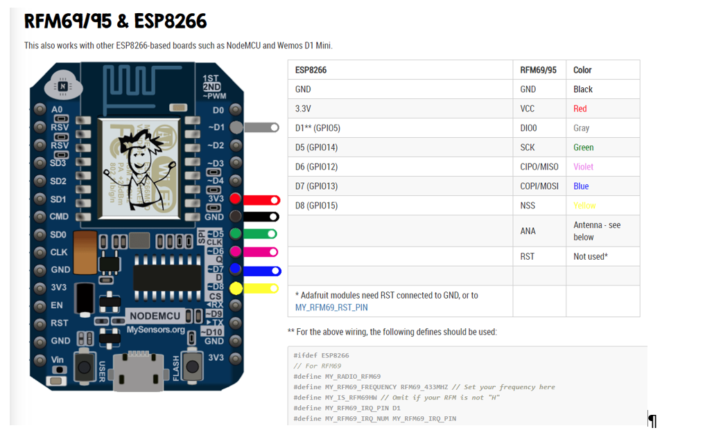
This is my wiring. I should add that I initially wired the RFM69-radio wrong (was not aware that the pinout was different for a RFM69HCW compared to a non H-version). I checked it with my fluke and all is correct connected, no shorts detected either.
I tested with the NodeMcu connected to radio but also with the NodeMCU only connected to usb (nothing else). Totally I have tested 3 nodeMcu:s. The basic "blink"-example will operate both in solo and with radio connected.
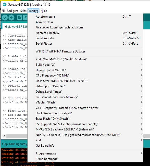
Im starting to think that the NodeMCU version "3.4" Link to desc. is different from the version 2 used in the mySensors-example. Maybe there is a compiler-setting that needs to be altered?

Wiring done after this guiding:

My code is as follows (ie just copy paste from the examples and editing the SSID and password)
/*
   The MySensors Arduino library handles the wireless radio link and protocol
   between your home built sensors/actuators and HA controller of choice.
   The sensors forms a self healing radio network with optional repeaters. Each
   repeater and gateway builds a routing tables in EEPROM which keeps track of the
   network topology allowing messages to be routed to nodes.

   Created by Henrik Ekblad <henrik.ekblad@mysensors.org>
   Copyright (C) 2013-2019 Sensnology AB
   Full contributor list: https://github.com/mysensors/MySensors/graphs/contributors

   Documentation: http://www.mysensors.org
   Support Forum: http://forum.mysensors.org

   This program is free software; you can redistribute it and/or
   modify it under the terms of the GNU General Public License
   version 2 as published by the Free Software Foundation.

 *******************************

   REVISION HISTORY
   Version 1.0 - Henrik Ekblad
   Contribution by a-lurker and Anticimex,
   Contribution by Norbert Truchsess <norbert.truchsess@t-online.de>
   Contribution by Ivo Pullens (ESP8266 support)

   DESCRIPTION
   The EthernetGateway sends data received from sensors to the WiFi link.
   The gateway also accepts input on ethernet interface, which is then sent out to the radio network.

   VERA CONFIGURATION:
   Enter "ip-number:port" in the ip-field of the Arduino GW device. This will temporarily override any serial configuration for the Vera plugin.
   E.g. If you want to use the default values in this sketch enter: 192.168.178.66:5003

   LED purposes:
   - To use the feature, uncomment any of the MY_DEFAULT_xx_LED_PINs in your sketch, only the LEDs that is defined is used.
   - RX (green) - blink fast on radio message received. In inclusion mode will blink fast only on presentation received
   - TX (yellow) - blink fast on radio message transmitted. In inclusion mode will blink slowly
   - ERR (red) - fast blink on error during transmission error or receive crc error

   See https://www.mysensors.org/build/connect_radio for wiring instructions.

   If you are using a "barebone" ESP8266, see
   https://www.mysensors.org/build/esp8266_gateway#wiring-for-barebone-esp8266

   Inclusion mode button:
   - Connect GPIO5 (=D1) via switch to GND ('inclusion switch')

   Hardware SHA204 signing is currently not supported!

   Make sure to fill in your ssid and WiFi password below for ssid & pass.
*/

// Enable debug prints to serial monitor
#define MY_DEBUG

// Use a bit lower baudrate for serial prints on ESP8266 than default in MyConfig.h
#define MY_BAUD_RATE 9600

// Enables and select radio type (if attached)
//#define MY_RADIO_RF24
#define MY_RADIO_RFM69 //Tried with and without commenting out RFM69
//#define MY_RADIO_RFM95
#define MY_RFM69_FREQUENCY RFM69_433MHZ // Set your frequency here
#define MY_IS_RFM69HW // Omit if your RFM is not "H"
#define MY_RFM69_IRQ_PIN D1
#define MY_RFM69_IRQ_NUM MY_RFM69_IRQ_PIN
#define MY_RFM69_CS_PIN D8 // NSS. Use MY_RFM69_SPI_CS for older versions (before 2.2.0)


#define MY_GATEWAY_ESP8266

#define MY_WIFI_SSID "xxxx"
#define MY_WIFI_PASSWORD "xxxxx"

// Enable UDP communication
//#define MY_USE_UDP  // If using UDP you need to set MY_CONTROLLER_IP_ADDRESS or MY_CONTROLLER_URL_ADDRESS below

// Set the hostname for the WiFi Client. This is the hostname
// it will pass to the DHCP server if not static.
#define MY_HOSTNAME "ESP8266_GW"

// Enable MY_IP_ADDRESS here if you want a static ip address (no DHCP)
//#define MY_IP_ADDRESS 192,168,178,87

// If using static ip you can define Gateway and Subnet address as well
//#define MY_IP_GATEWAY_ADDRESS 192,168,178,1
//#define MY_IP_SUBNET_ADDRESS 255,255,255,0

// The port to keep open on node server mode
#define MY_PORT 5003

// How many clients should be able to connect to this gateway (default 1)
#define MY_GATEWAY_MAX_CLIENTS 2

// Controller ip address. Enables client mode (default is "server" mode).
// Also enable this if MY_USE_UDP is used and you want sensor data sent somewhere.
//#define MY_CONTROLLER_IP_ADDRESS 192, 168, 178, 68
//#define MY_CONTROLLER_URL_ADDRESS "my.controller.org"

// Enable inclusion mode
//#define MY_INCLUSION_MODE_FEATURE

// Enable Inclusion mode button on gateway
//#define MY_INCLUSION_BUTTON_FEATURE
// Set inclusion mode duration (in seconds)
//#define MY_INCLUSION_MODE_DURATION 60
// Digital pin used for inclusion mode button
//#define MY_INCLUSION_MODE_BUTTON_PIN D1

// Set blinking period
//#define MY_DEFAULT_LED_BLINK_PERIOD 300

// Flash leds on rx/tx/err
// Led pins used if blinking feature is enabled above
//#define MY_DEFAULT_ERR_LED_PIN 16  // Error led pin
//#define MY_DEFAULT_RX_LED_PIN  16  // Receive led pin
//#define MY_DEFAULT_TX_LED_PIN  16  // the PCB, on board LED

#include <MySensors.h>

void setup() {
  // initialize digital pin LED_BUILTIN as an output.
  pinMode(LED_BUILTIN, OUTPUT);
}

// the loop function runs over and over again forever
void loop() {
  // Below is blink-example, tried with and without this code - ie empty loop() and setup()
  digitalWrite(LED_BUILTIN, HIGH);   // turn the LED on (HIGH is the voltage level)
  delay(1000);                       // wait for a second
  digitalWrite(LED_BUILTIN, LOW);    // turn the LED off by making the voltage LOW
  delay(1000);                       // wait for a second
}

void presentation()
{
  // Present locally attached sensors here
}
-
Problems ethernet GW with ESP8266- NodeMcu V3.4Trying to accomplish a ethernet GW with ESP8266 + RFM69.
Im using the GatewayESP8266-example. It compiles and downloads apparently ok, but it will not run. There is no output on the serial monitor (apart from the boot message on baudrate 74880) I tried all other available baudrates with no success/outputs.
23:33:01.222 ->  ets Jan  8 2013,rst cause:2, boot mode:(3,6)
23:33:01.222 ->
23:33:01.222 -> load 0x4010f000, len 3460, room 16
23:33:01.255 -> tail 4
23:33:01.255 -> chksum 0xcc
23:33:01.255 -> load 0x3fff20b8, len 40, room 4
23:33:01.255 -> tail 4
23:33:01.255 -> chksum 0xc9
23:33:01.255 -> csum 0xc9
23:33:01.255 -> v00047740
23:33:01.255 -> ~ld
Im using board library version 3.02 for the ESP8266 (selecting NodeMCU 1.0 (ESP-12E Module)). Latest version for Mysensors (2.3.2)
I tried to run the nodeMcu board stand alone and connected to the RFM69HCW, no difference.
As a test I have tried the arduino-included basic "blink", which works. I then added the blink-part to the GatewayESP8266-example => no flashing led.
Im using the NodeMCU v3.4 version 'Lolin'.
The instruction mentions specific wiring for "barebone" ESP8266 to switch between download/run code. Is my NodeMCU v3.4 barebone? I assume it does not need specific wiring as the blink-example is able to run?
Any help appreciated. Thanks!
-
OH3, RPi3, GPIO-NRF24 gateway. MySensors binding (ETH or MQTT?)Replying myself after more reading and testing.
*MQTT vs ETH probably is equivalent in my system, if the choice if given I think MQTT is preferred.
*NRF24 or RFM69, maybe both as I already have a bunch of NRF24 radios home and can start build directly.
*PC based MQTT could be an idea, but probably its as easy to work through an Arduino-example using the serial monitor in an Arduino-environment.My way forward will be:
Remove the RPi-GPIO-gateway (I built a basic node and tested it, but could not communicate with the GW) and replace it with ESP8266-based WIFI/MQTT/Radio-gateway (one with NRF24 and eventually one with RFM69).I believe that will be an easier way into mySensors-world also limiting the amount of required Linux-related knowledge. It will be easier to debug the system from Arduino IDE-serial console. Ie start and confirm OH3 to MySensors-MQTT-gateway, then proceeding with sensor to gateway communication etc.
-
OH3, RPi3, GPIO-NRF24 gateway. MySensors binding (ETH or MQTT?)Im a newbie with mySensors. Got interested a few years ago but never got to spend the time to get it up and running. My current system basically consists of RasberryPi3, OH3 and 433Mhz-Nexa-modules (Rfxcom/usb-gateway) that works without any problem.
Now I would like to integrate a relay-board (to control my house ventilation - FTX) into the system as well as some different temp/humidity-sensors and was thinking to do that through MySensors.
System consists of RPI3 + Openhab 3.1.0,
The gateway is the GPIO-mounted module based on NRF24L01+ (https://www.mysensors.org/hardware/rpi-gw-nrf)
Followed the steps presented here to get it up running https://www.mysensors.org/build/raspberry
The OH-mySensors-binding is the one provided by @vores8 in separate thread (https://forum.mysensors.org/topic/11482/oh3-mysensors-binding/114)With a lot of effort and forum-reading I believe the system is fully up and running although Im not 100% sure as I have no sensors yet (thats next step for me).
My questions
My first impression was that the OH-Mysensors-binding no longer was supported and therefore went with the MQTT-based GW. Now I see the binding is working (although not officially supported) and so ETH should still be an option. Should I go for MQTT or ETH based gateway solution and whats the pros and cons?Next question. I understand that solutions based on NRF24 is somewhat outdated and a solution with RFM69 is preferred. Should I stop right here and switch for a system based on RFM69 instead?
As i have no sensors in the system yet, is there an easy way to test the system? Thinking a PC-based MQTT-client that supports mySensors-format? (i already found the MQTT-explorer that I think will be helpful).
Thanks
Per
