@mfalkvidd So keep trying IRLZ44N FETs?
pjblink
Posts
-
💬 Dimmable LED Actuator -
💬 Dimmable LED ActuatorHi guys,
Struggling with this a little and think it may be hardware related. I'm using a 3.3v pro mini and it won't let the 12v LEDs go to full brightness, at max dim level they're still quite dim. I've tried this on both regular flexi LED strip and the copper-wire type LEDs (final project is based on these).
I've tried with a different FET, an IRLB8721 and that goes to full brightness however won't switch the LEDS off completely so guessing there's a leak from that FET! I'm not sure if that's normal or not. Frustrating.
Ideally i want the circuitry to be 3.3v as i'm already converting the 12v LED power supply down to 3.3v for the nRF. I'd rather not have a 5v and 3.3v regulator.
Thanks,
Patrick
-
Motion controlled dimmable LED porch light@5546dug Hi Doug,
Here you go. Annoyingly my PIR seems to have died after a week or so. Hoping it's a faulty unit rather than anything to do with the circuit. I've ordered another, and will see how it holds up. It seems i can trigger it by touching the unit in places, but the PIR sensor itself is dead and not detecting anything.
/* AC Light Control Uses up and down buttons to set levels makes use of a timer interrupt to set the level of dimming */ #include <SPI.h> #include <MySensor.h> #include <TimerOne.h> #define SN "AC LED Porch Dimmer Control" #define SV "1.3" #define NODE_ID 30 //change to a number to assign a specific ID #define FADE_DELAY 20 // Delay in ms for each percentage fade up/down (10ms = 1s full-range dim) #define MOTION_CHILD 1 //ID of the motion sensor child #define MOTION_PIN 2 // Arduino pin tied to trigger pin on the motion sensor. volatile int i=0; // Variable to use as a counter of dimming steps. It is volatile since it is passed between interrupts volatile boolean zero_cross=0; // Flag to indicate we have crossed zero int AC_pin = 7; // Output to Opto Triac int freqStep = 75; // This is the delay-per-brightness step in microseconds. It allows for 128 steps // If using 60 Hz grid frequency set this to 65 MySensor gw; //dimming static int currentLevel = 128; // Current dim level... uint8_t fadeLevel = 128; //used to store the fade level when using the buttons //motion sensor uint8_t lastMotion = 0; unsigned long previousMillis = 0; // last time update //see http://stackoverflow.com/questions/10773425/performing-a-function-after-x-time for more details on this unsigned long motionDelay = 10000; // interval at which to keep motion sensor trippped (milliseconds). Used to prevent too frequent updates to Vera. boolean metric = true; MyMessage dimmerMsg(AC_pin, V_DIMMER); MyMessage lightMsg(AC_pin, V_LIGHT); MyMessage motionMsg(MOTION_CHILD, V_TRIPPED); void setup() { // Begin setup Serial.begin(115200); Serial.println( SN ); gw.begin( incomingMessage, NODE_ID, true); // Register the LED Dimmable Light with the gateway gw.present( 6, S_DIMMER ); gw.sendSketchInfo(SN, SV); // Pull the gateway's current dim level - restore light level upon sendor node power-up gw.request( 6, V_DIMMER ); gw.present(MOTION_CHILD, S_MOTION); //Setup AC PIN pinMode(AC_pin, OUTPUT); // Set the Triac pin as output attachInterrupt(1, zero_cross_detect, RISING); // Attach an Interupt to Pin 2 (interupt 0) for Zero Cross Detection Timer1.initialize(freqStep); // Initialize TimerOne library for the freq we need Timer1.attachInterrupt(dim_check, freqStep); // Go to dim_check procedure every 75 uS (50Hz) or 65 uS (60Hz) // Use the TimerOne Library to attach an interrupt } void zero_cross_detect() { zero_cross = true; // set flag for dim_check function that a zero cross has occured i=0; // stepcounter to 0.... as we start a new cycle digitalWrite(AC_pin, LOW); } // Turn on the TRIAC at the appropriate time // We arrive here every 75 (65) uS // First check if a flag has been set // Then check if the counter 'i' has reached the dimming level // if so.... switch on the TRIAC and reset the counter void dim_check() { if(zero_cross == true) { if(i>=fadeLevel) { digitalWrite(AC_pin, HIGH); // turn on light i=0; // reset time step counter zero_cross=false; // reset zero cross detection flag } else { i++; // increment time step counter } } } void loop() { gw.process(); //motion sensor code unsigned long currentMillis = millis(); if(currentMillis - previousMillis > motionDelay){ uint8_t motionDetect = digitalRead(MOTION_PIN); if(motionDetect != lastMotion){ // Serial.print("motionDetect Value: "); // Serial.println(motionDetect); gw.send(motionMsg.set(motionDetect)); // Send tripped value to gw if(motionDetect == 1){ previousMillis = currentMillis; //"Tripped" delay } else{ previousMillis = currentMillis - motionDelay + 1000; //"Not tripped" delay for 1 second to stop rapid "not tripped" and "tripped" updates to Vera } lastMotion = motionDetect; } } } void incomingMessage(const MyMessage &message) { if (message.type == V_LIGHT || message.type == V_DIMMER) { // Retrieve the power or dim level from the incoming request message int requestedLevel = atoi( message.data ); // Adjust incoming level if this is a V_LIGHT variable update [0 == off, 1 == on] requestedLevel *= ( message.type == V_LIGHT ? 100 : 1 ); // Clip incoming level to valid range of 0 to 100 requestedLevel = requestedLevel > 100 ? 100 : requestedLevel; requestedLevel = requestedLevel < 0 ? 0 : requestedLevel; float percent_level; percent_level = 128 - (requestedLevel * 1.28); fadeToLevel( percent_level ); Serial.print( "Changing level to " ); Serial.print( requestedLevel ); Serial.print( ", from " ); Serial.println( currentLevel ); // Inform the gateway of the current DimmableLED's SwitchPower1 and LoadLevelStatus value... //gw.send(lightMsg.set(currentLevel > 0 ? 1 : 0)); // hek comment: Is this really nessesary? // gw.send( dimmerMsg.set(requestedLevel) ); } } /*** * This method provides a graceful fade up/down effect */ void fadeToLevel( int toLevel ) { Serial.print("currentLevel Value: "); Serial.println(currentLevel); Serial.print("toLevel Value: "); Serial.println(toLevel); int delta = ( currentLevel - toLevel ) < 0 ? 1 : -1; Serial.print("delta Value: "); Serial.println(delta); while ( currentLevel != toLevel ) { currentLevel += delta; fadeLevel= ((int)currentLevel); delay( FADE_DELAY ); //fadeLevel = toLevel; } }``` -
Motion controlled dimmable LED porch lightNo problem, happy I could have been of some help!
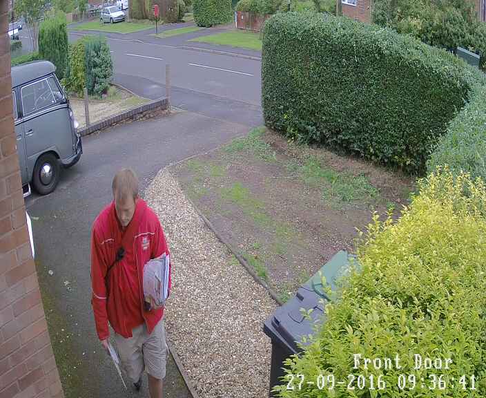
What's nice is that mysensors triggers so fast that it grabs a security cam image from before the camera has caught up!! Excuse the driveway...
-
Motion controlled dimmable LED porch lightHi all,
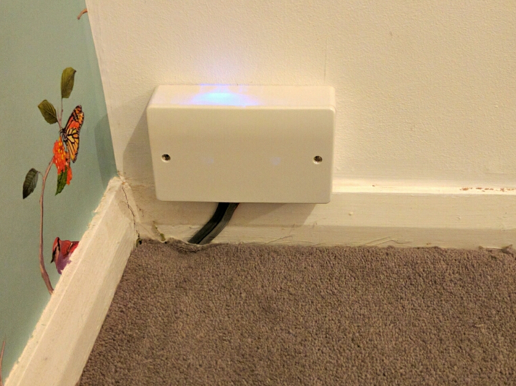
Just wanted to show you all my motion-activated LED Porch Light. Lots of 12v LED lights on here, not so many mains AC-powered bulb projects, so I thought I'd show you mine. Sketch is a standard motion sensor interrupt sketch alongside a dimming sketch, I'm sure I got it from the forums. Initially I wanted it to perform local control of the lamp via the PIR but then decided I wanted the light to come on low (33%) from dusk till dawn, and then raise to 100% when it detects motion. Because of that I've left the control logic to Vera. Below about 30% the bulb shows an obvious unstable flicker so I don't go there! Dimming and ramp up/down is beautifully smooth.
It consists of:
Arduino Nano
NRF24L01 radio
HLK-PM01 240v AC>5v DC
HC-SR501 (PIR)
240v AC Phase control dimming circuit: http://www.ebay.com/itm/111764492631
4w dimmable filament LED bulb
Wall box with blanking plate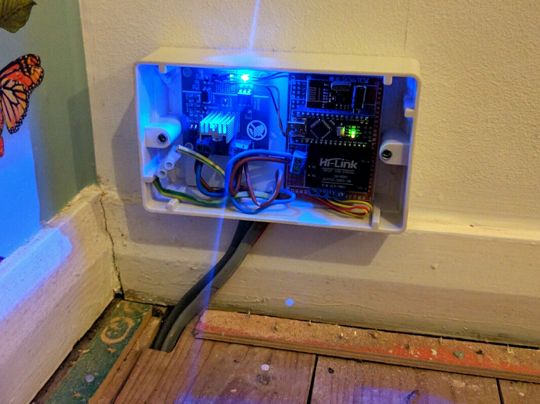
-
Multisensor PIR based on IKEA MolganHi guys,
I'm struggling with this one unfortunately, i can't get it to trip/untrip.
Sketch is identical to the motion example.
I've removed the photo diode (not bridged the gap, it looks like bridging the gap stops it from tripping at all, leaving it open means it trips whatever the light level is). This was tested without connecting to the arduino, working as normal.
So i've removed resistor 17, and connected my arduino pin 4 up to the chip side of where R17 was. I'm running the main board of the existing power lines, but i've tapped into the + of the middle battery and that's going to VCC on the arduino. Arduino nano GND is connected to the main board -.
Where am I going wrong? I've tried this on two boards now and they're both acting the same. Serial monitor is just showing me:
send: 14-14-4-0 s=1,c=1,t=16,pt=0,l=1,sg=0,st=ok:1
1
send: 14-14-4-0 s=1,c=1,t=16,pt=0,l=1,sg=0,st=ok:1
1
send: 14-14-4-0 s=1,c=1,t=16,pt=0,l=1,sg=0,st=ok:1
1Thanks,
Patrick
-
How To - Doorbell Automation HackIt still looks to be having issues :( looks like the arduino will hang just before sending the command to untrip.
-
How To - Doorbell Automation HackSo it kept failing after 2 or 3 rings...frustrating! I enabled all the debug and noticed it kept failing just before sending out the "off" message. It didn't reset, just stalled. This was the case even when powered by USB. And then I remembered how sensitive the NRFs are to fluctuations in power and I hadn't got round to putting a cap on there yet!!! I put a spare 1000uF (47uF are on order) and so far it hasnt caused me any further issues! So now I've got 3 huge capacitors on there, and it looks ok...touch wood.
-
How To - Doorbell Automation Hack@sundberg84 That was definitely on the cards...but it looks like I might have got it working. I did 4 things in one go, which is unlike me, so now I have to break things down to see which one helped (if it wasn't all)...1st thing was a 4700uF cap over the arduino VIN/GND, 2nd was a 1000uF cap over the relay +- 5v,… 3rd was to reflow a few of the GND solders and finally I dropped the voltage regulator from 8v to just under 7v...and hey presto...
-
How To - Doorbell Automation HackI've just tried it with both 1000uF and then a 4700uF cap across VIN/GND on the arduino with only slightly better results. It'll ring, but the relay stays open most of the time and the arduino needs resetting to release it :(
-
How To - Doorbell Automation HackWorking without the doorbell load attached:
mysensors enabled doorbell working without loadFailing when I attach the load:
mysensors enabled doorbell failing with load -
How To - Doorbell Automation HackHi crodgers,
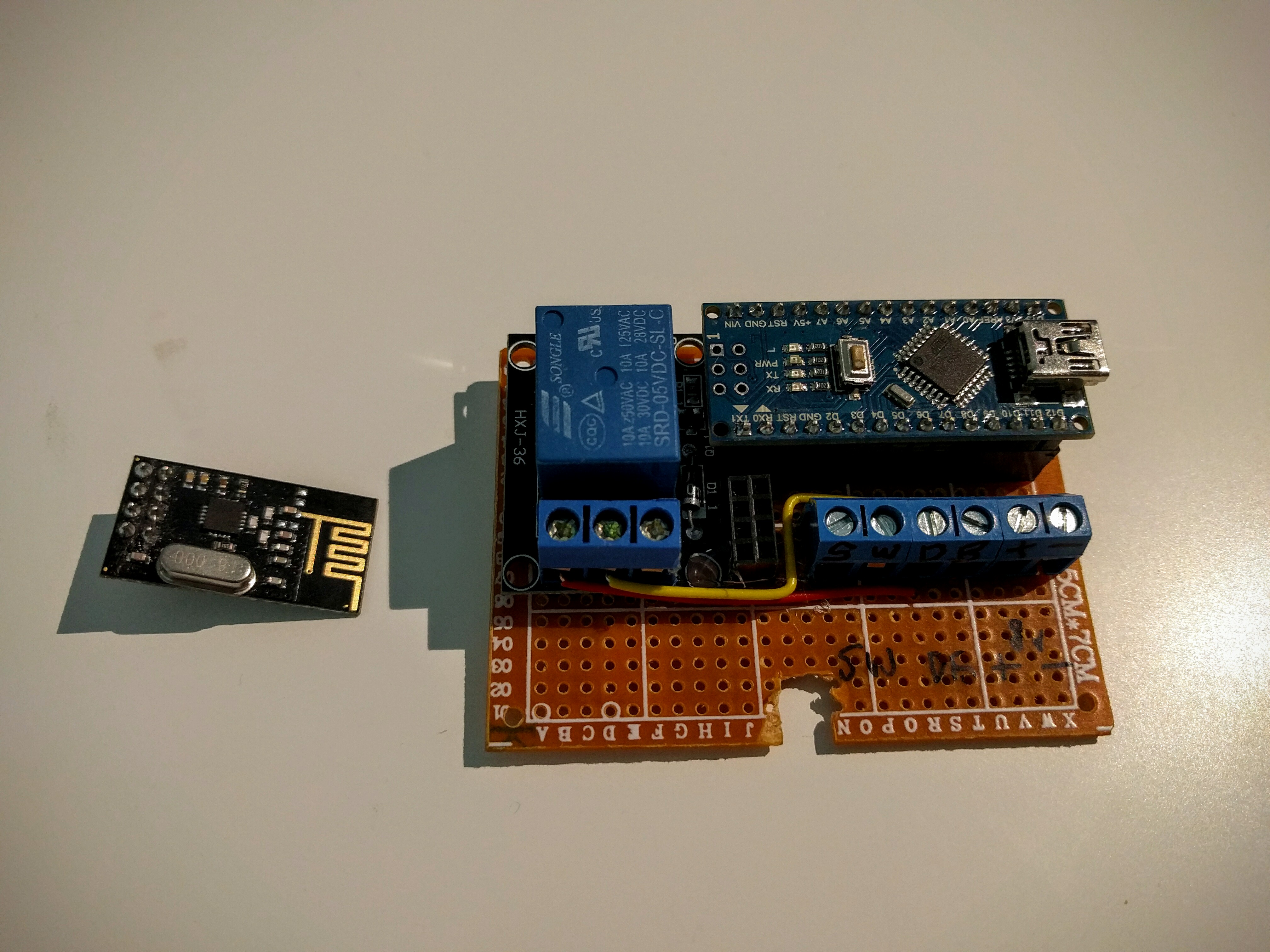
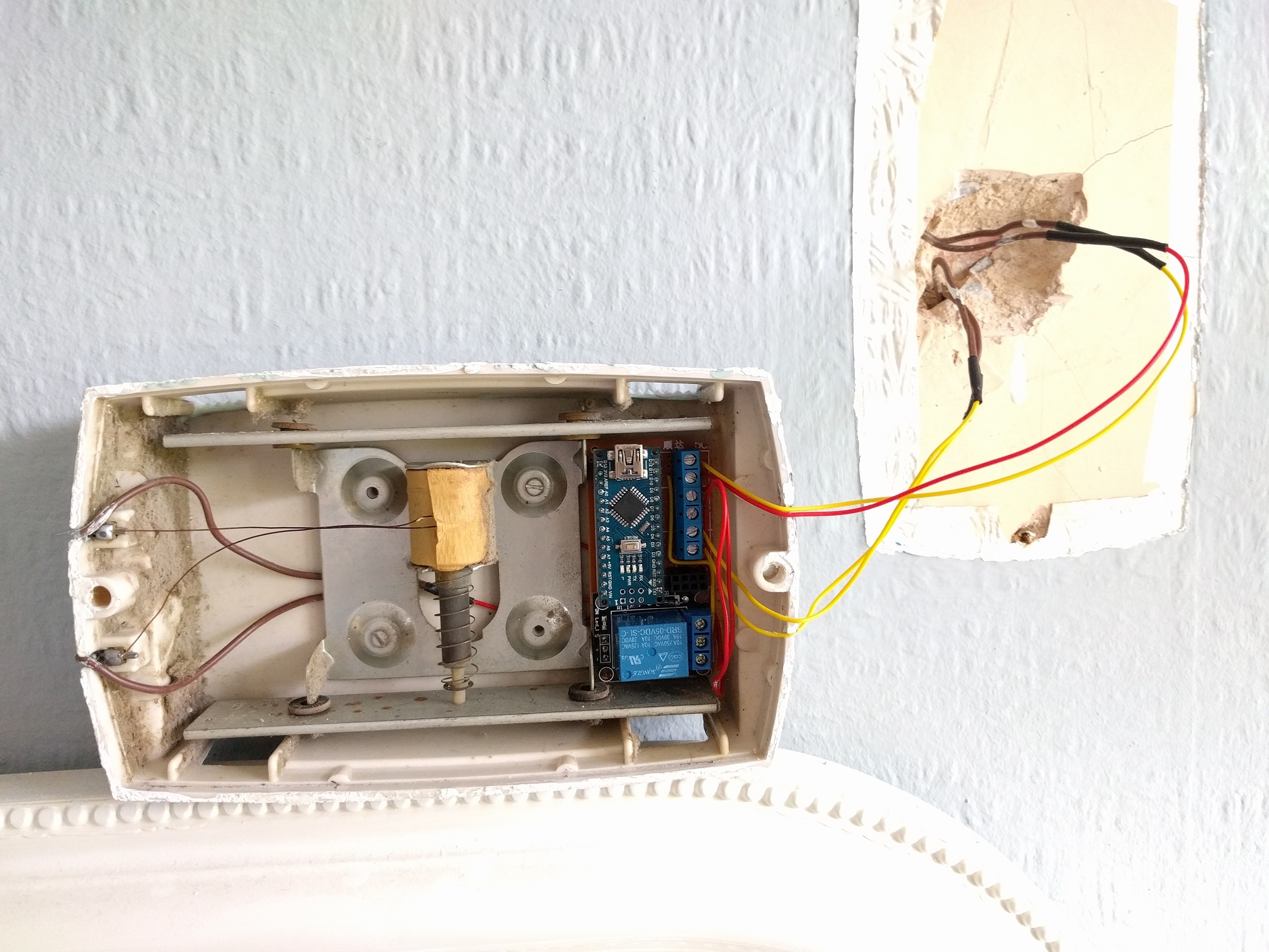
So yeh, there's a nano on headers, relay, nrf on headers and 3 wire terminals - 1 for the doorbell button, 1 for the bell itself and another for the DC IN. Everything is soldered to a prototyping board which has now been trimmed down to fit in the doorbell housing.
Thanks,
Patrick
-
How To - Doorbell Automation HackOr can i just get away with a better power supply for the both? Essentially I've got a pulse-detecting mysensors node, a doorbell node and a doorbell itself running off a cheap-ass ebay chinese full-bridge rectifier and step-down converter (120v AC > 8v DC). The doorbell takes 8v DC so I'm using that as the common voltage.
-
How To - Doorbell Automation HackHi guys,
I'm nearly there, but need a little help if anyone can!
For my setup I've got a diode bridge followed immediately by a buck converter, so the doorbell's 18v AC comes down to 8v DC. My plan was to run the doorbell AND the arduino off this same supply, but I'm guessing now that it may not be possible. The reason for this was down to there only being 2 wires to the doorbell. The doorbell works fine off 8v DC and so does the arduino. The issue however is when i both power the arduino and the doorbell at the same time of the same supply. The relay opens and then the arduino resets. No chime.
What should I do? Wiring layout is exactly the same as above but the 8v DC loops through the relay to the doorbell as well as going to VIN/GND on the Arduino Nano.
I can't have the arduino at the power supply end as I need the doorbell button connections, so I'm hoping someone might have some ideas around splitting out the power supplies at the doorbell end? Or smoothing it or something like that.
Power is red/yellow from the wall. Doorbell button is yellow/yellow from the wall. brown/brown is soldered/heat shrunk to red/red within the housing. NRF is on headers, so it's lifted out in this photo.
Thanks,
Patrick
