Next logic step is flipping polarity like here: http://gardenbot.org/howTo/soilMoisture/
R
rollercontainer
@rollercontainer
Posts
-
💬 Soil Moisture Sensor -
Why I quit using MySensors for actuatorsMy communication problems vanished by exchanging the amplified version by a normal NRF24.
-
RGB LED strip controller with FastLEDHi,
I built a 1m x 1,5m accoustic absorber with Basotect for the ceiling in my living room. To generate ambient lighting, I installed a non-smart analog 5m LED strip on the top side. My first attempt was to use PWM from arduino which resultet in visual steps when do slow fading. Next approcach was a 12bit PWM motor shield, resulting in 4096 steps which were smooth but I couldn't use the real good FastLED library. So I ended up with a P9813 RGB MosFET Board from ebay which represents a single pixel. (But can easily chained for several strips in the room.) FastLED is dithering between the 256 steps of the arduino and produces very smooth transitions.
Hardware:
- Arduino Nano (~5€)
- NRF24L01 (~2€)
- P9813 RGB MosFet Board from ebay (Full Color RGB LED Strip Driver Sensor v1.1 for Arduino STM32 AVR P9813) (4,29€)
- LM2596S DC-DC Step-Down Converter for 12V->5V (~1€)
- 5m RGB LED Strip ( < 10€)
- old 12V laptop power supply
Software:
My setup is a mqttClientGateway and a raspi with node-red.
To change color, you can send a RRGGBB string to mysensors-in/node-id/0/1/0/40
To change the fade time you can send a integer from 0 to 255 to mysensors-in/node-id/1/1/0/24
To persist the current settings to eeprom you can send a "1" (meaning bool "true") to mysensors-in/node-id/2/1/0/2
To set the brightness you can send 0 to 100 (V_PERCENTAGE) to mysensors-in/node-id/3/1/0/3https://github.com/rollercontainer/nanoP9813FastLEDMySensors/blob/master/main.cpp
This code is working. Nevertheless it could be a lot better. It is posted, to help people take code lines or inspirations out of it. I think, I change the setup to esp8266 because of the OTA flash ability.
Greetings
-
My Slim 2AA Battery Nodesearched a bit and found that @ceech already made a harvester with a coin cell.
http://www.ebay.de/itm/BQ25570-thermal-solar-energy-harvester-/332071662285
still too big and too expensive in comparison with dozens of alkaline batteries which will run for years, but that is the way to go sometime.
-
My Slim 2AA Battery NodeDid you considered a tiny solar cell like enocean does?
https://www.enocean.com/en/enocean_modules/stm-320/
That would be perfect... -
My Slim 2AA Battery NodeMaybe its better to measure the voltage every 10 or 100 loops and only send one custom message/alert when its dropped below a threshold. I am using the MQTTClientGateway and Node-Red. In case of a battery-low message, node-red could send me an email with the node name. I will give it a try...
From https://www.mysensors.org/download/serial_api_20:
V_TEXT 47 Text message to display on LCD or controller device S_INFO V_CUSTOM 48 Custom messages used for controller/inter node specific commands, preferably using S_CUSTOM device type. S_CUSTOM``` -
My Slim 2AA Battery NodeJust noticed, that I use another login at home. So, the Tim-Abels is the rollercontainer... Sorry for that.
-
My Slim 2AA Battery Node@AWI one step forward, two steps back... Thanks for the hint.
I guess, I should send battery percentage every 10 interrupts or so. Even if the contact doesn't trigger for a while, I can force it by showing my neighbours my ocd on doors ^^ (knock, knock, knock - Penny!)
What do you think?
-
My Slim 2AA Battery NodeMaybe there is something like a counter (variable++) which causes a overflow after two month?
-
My Slim 2AA Battery Node@AWI said in My Slim 2AA Battery Node:
@rollercontainer Your sleep looks good. Did you remove this piece of code?
// Activate internal pull-ups
	digitalWrite(PRIMARY_BUTTON_PIN, HIGH);
	digitalWrite(SECONDARY_BUTTON_PIN, HIGH);
Take a look at this thread for a < 1 uA consumption...
Hmm, I noticed, that I have to disable the internal pullups. But instead of removing the lines, I set them to LOW. I will test it without the lines and come back. Thank you @AWI.
-
My Slim 2AA Battery Node@sundberg84: Thanks, so I will stick to my 12µA :-)
@AWI: I am using sleep with Interrupt as in this example:
sleep(PRIMARY_BUTTON_PIN-2, CHANGE, SECONDARY_BUTTON_PIN-2, CHANGE, 0); -
My Slim 2AA Battery NodeI only come down to 12µA with one reed switch, 1MOhm pullup, 1Mhz bootloader and the binarySwitchSleepSketch. Measured with two different multimeters. This is nearly ten times higher than in the first posting. Changing all internal pullups to LOW doesn't change anything.
Is there a way to optimize the power consumption or is it "good enough" ?
-
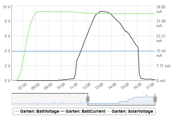
Multisensor node using Ceech boardCan someone explain, why the charger isnt charging all the time or at least earlier? BattVoltage is 3.96V on the right end. Is the cell considered full?
-
Multisensor node using Ceech boardD'oh! I thought, the wiper of the trimmer is at the flat side, but its opposite to the flat, got it finally. Now pimatic is showing a current (0.74A).
-
Multisensor node using Ceech boardOk, now I've got a 12V 50mA solar cell and a 3,7V 2000mAh LiPo. Potentiometer is at 12 o'clock (flat segment at the single solder pad)
Can you please try to explain what exactly the potentiometer is adjusting?
Does the charger only charge if the cell voltage is below the adjusted voltage level?Your example sketch is not showing any charging current:
Vcc = 3.32V
Charge current = 0.00mA
Solar cell voltage = 0.24V
Battery voltage = 3.79V
CHRG = 424
Vcc = 3.32V Charge current = 0.00mA Solar cell voltage = 7.44V Battery voltage = 3.79V CHRG = 409Vcc = 3.32V Charge current = 0.00mA Solar cell voltage = 11.72V Battery voltage = 3.79V CHRG = 0 -
Multisensor node using Ceech boardI wanted to use it outside for collecting weather data. But the battery which the board is designed for isn't suitable for temperatures below 0°C.
Is that right so far?
Or did you successfully used Li-Ion outside below 0°C?
-
Multisensor node using Ceech board -
Multisensor node using Ceech boardI thought, sunset will be enough to terminate charging on NiCd?
So its easier to take 3,2V LiFePo4, right? And because my board only regulates down, I have to take 2 in series to provide enough voltage to regulate, right?
All these flat LiPo types provide ~3,7V. Is that enough to feed the regulator (+dropout)?
-
Multisensor node using Ceech boardI am not amused...
I will buy additonal batteries and a second solar cell.
-
Multisensor node using Ceech boardIn the ebay auction I bought it your text says buck boost converter. On the chip there is a number gnq 666 601, but I cant find him. Board says: 77534K_Y471