Skip to content
  • OpenHardware.io
  • Categories
  • Recent
  • Tags
  • Popular
Skins
  • Light
  • Brite
  • Cerulean
  • Cosmo
  • Flatly
  • Journal
  • Litera
  • Lumen
  • Lux
  • Materia
  • Minty
  • Morph
  • Pulse
  • Sandstone
  • Simplex
  • Sketchy
  • Spacelab
  • United
  • Yeti
  • Zephyr
  • Dark
  • Cyborg
  • Darkly
  • Quartz
  • Slate
  • Solar
  • Superhero
  • Vapor

  • Default (No Skin)
  • No Skin
Collapse
Brand Logo
S

stephenmhall

@stephenmhall
  • Getting Started
  • Controller
  • Build
  • Hardware
  • Download/API
  • Forum
  • Store
About
Posts
71
Topics
10
Shares
0
Groups
0
Followers
2
Following
1

Posts

Recent Best Controversial

  • Boiler control from MAX! Cube to Drayton Boiler via Raspberry Pi/Vera/Mysensors.
    S stephenmhall

    Hi Guys. A rather specific project that may not be much use to many others but maybe of interest if you are looking for individual radiator heater control.

    I tried the Stella-Z radiator controllers with Vera and in all honesty they were crap, they talk to the system only rarely and they only hold one setpoint at a time, all in all no good.

    So I ended up getting a full set of the eq-3 MAX! kit with 7 radiator controllers, 3 wall thermostats an eco button and the central Cube controller. Apart from the supplied software being a little annoying with it sometimes messing with the heating times it is great. I solved the software problem in the app store with MAX! Remote unofficial replacement software, very good. The only problem I was left with was my Boiler.

    British Gas Boiler fitted with a single wireless wall thermostat in the living room. I had already upgraded the simple thermostat to a Drayton +3RF giving me daily timings but it still just took the one temperature. The problem being if the temp was up in the living room at night the heat would go off and the bedrooms would not heat up for going to bed.

    So to my solution. I already have a Vera automation controller and Mysensors nodes, so I now have a Raspberry Pi that polls the Cube to get all the valve open percentages if it decides the boiler needs to be on it sends a message to the Vera which transmits out on a Mysensors 433Mhz transmitter node to turn the boiler on. The Rpi has a web interface accessible in the house so I can see current temps and boiler state and also a graph of past temps for each room. I hope to implement the Cube controls in the web interface eventually so I don't need 2 pieces of software.

    Web UI
    2015-11-29.png

    Graph
    2015-11-29 (1).png

    Rpi2 very stock and I code in Python
    Heating Pi2.jpg

    And Finally the Mysensor Board, Just done today, has been running on a breadboard until now.
    heating_Mysensor.jpg

    It still needs a box printing.

    I could wire the RPi into the boiler switch direct but I want to have the old Thermostat as backup just in case.

    So if you have a Vera and MAX! radiator valves and an Rpi and a Drayton controlled Boiler, this is for you :)

    If anyone is interested I will post the code. It is very much my code as in an actual Python developer would go "What the!!" but it works. So far.

    My Project

  • Request: New Sensor Type ? Thermostatically controlled switch
    S stephenmhall

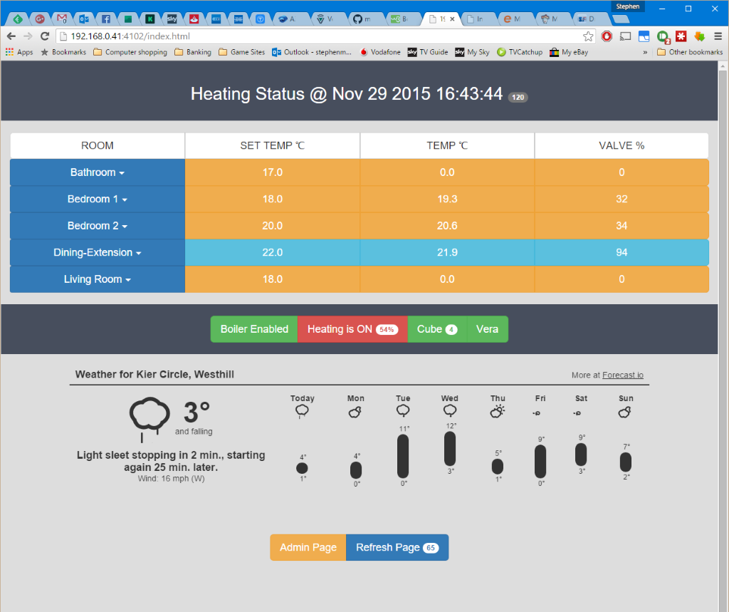
    I went with your suggestion, its definitely a work in progress, but there is progress.
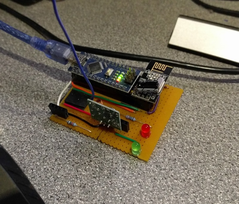
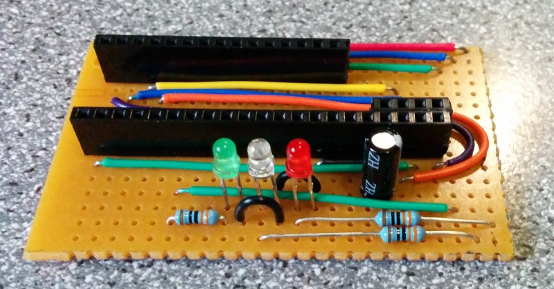
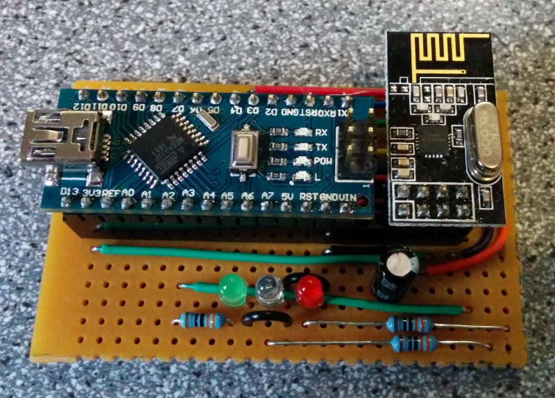
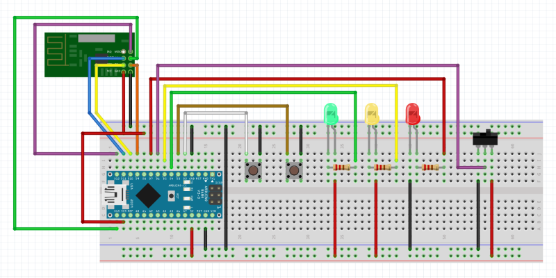
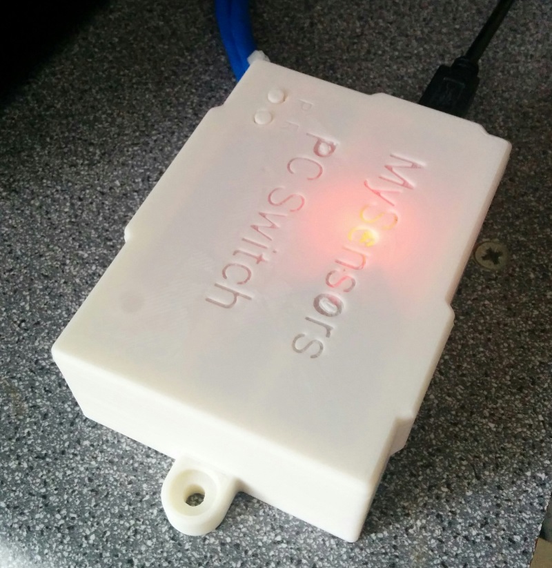
    I have a nano with DHT22 sensor and a relay for heating on/off.
    I played with the I_Arduino.xml and L_Arduino.lua files and added

    HVAC = {26, "urn:schemas-upnp-org:device:HVAC_ZoneThermostat:1", "D_HVAC_ZoneThermostat1.xml", "HVAC "}
    
    HVAC = {40, "urn:upnp-org:serviceId:TemperatureSetpoint1", "CurrentSetpoint", "" }
    
    function SetTheNewHvacTemp(device, NewCurrentSetpoint)
    	sendCommand(luup.devices[device].id,"HVAC",NewCurrentSetpoint)
    end
    

    to L_Arduino.lua

    and

    <action>
      <serviceId>urn:upnp-org:serviceId:TemperatureSetpoint1</serviceId>
        <name>SetCurrentSetpoint</name>
          <job>
            if (p ~= nil) then p.SetTheNewHvacTemp(lul_device, lul_settings.NewCurrentSetpoint)  end
      			return 4,0
          </job>
    </action>
    

    to I_Arduino.xml

    Also added V_HVAC and S_HVAC to MyMessage.h for Arduino.

    And I get this on Vera Edge UI7

    vera_arduino_hvac.png

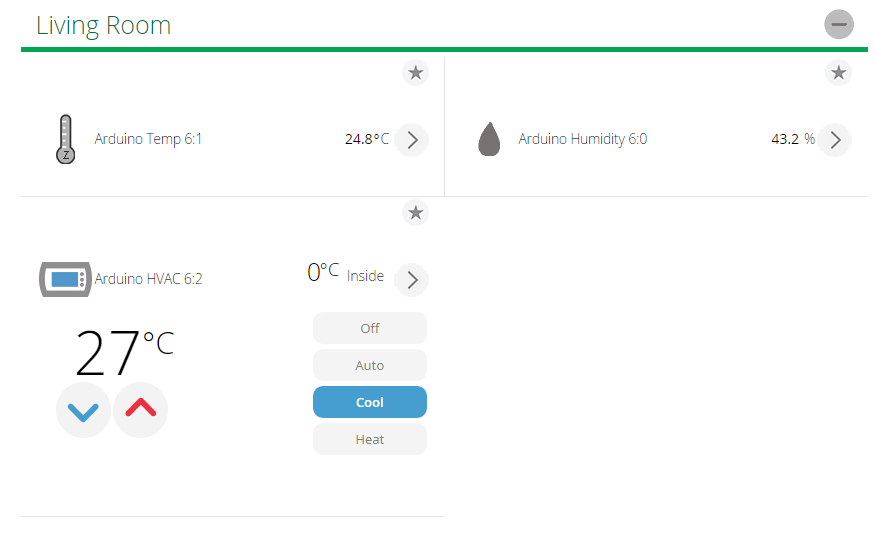
    As of now I can change the setpoint, although it comes back from the node as 27.6 which throws off the vera temp display, makes it 2 line but shows it, I can also send the states "CoolOn", "HeatOn" and so on.

    I haven't worked out how to get the temp on the card instead of separate, or the battery level yet.

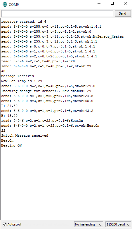
    Here is serial from node
    vera_arduino_hvac_serial.png

    Here is my node sketch

    #include <SPI.h>
    #include <MySensor.h>  
    #include <DHT.h>
    #include <Bounce2.h>
    
    #define NODE_ID AUTO
    #define SKETCH_NAME "MySensor_Heater"
    #define SKETCH_VERSION "1.1"
    #define NODE_REPEAT true
    
    #define CHILD_ID_HUM 0
    #define CHILD_ID_TEMP 1
    #define CHILD_ID_HVAC 2
    #define CHILD_ID_BATT 3
    #define CHILD_ID_HEATER_SW 4
    
    #define HUMIDITY_SENSOR_DIGITAL_PIN 3
    #define RELAY_PIN  4  // Arduino Digital I/O pin number for relay 
    #define BUTTON_PIN  5  // Arduino Digital I/O pin number for button 
    #define RELAY_ON 0
    #define RELAY_OFF 1
    unsigned long SLEEP_TIME = 30000; // Sleep time between reads (in milliseconds)
    
    Bounce debouncer = Bounce(); 
    int oldValue=0;
    bool state;
    MySensor gw;
    DHT dht;
    float lastTemp;
    float lastHum;
    boolean metric = true;
    unsigned long CHECK_TIME = millis();
    String heaterMode = "Off";
    int setPoint = 20;
    MyMessage msgHum(CHILD_ID_HUM, V_HUM);
    MyMessage msgTemp(CHILD_ID_TEMP, V_TEMP);
    MyMessage msgHeaterSW(CHILD_ID_HEATER_SW,V_HEATER_SW);
    //MyMessage msgHeaterState(CHILD_ID_HEATER_STATE,V_HEATER);
    MyMessage msgHvac(CHILD_ID_HVAC, V_HVAC);
    MyMessage msgBattery(CHILD_ID_BATT, I_BATTERY_LEVEL);
    
    void setup()  
    { 
      gw.begin(incomingMessage,NODE_ID,NODE_REPEAT);
      dht.setup(HUMIDITY_SENSOR_DIGITAL_PIN); 
    
      // Send the Sketch Version Information to the Gateway
      gw.sendSketchInfo(SKETCH_NAME, SKETCH_VERSION);
      
      // Setup the button
      pinMode(BUTTON_PIN,INPUT);
      // Activate internal pull-up
      digitalWrite(BUTTON_PIN,HIGH);
      
      // After setting up the button, setup debouncer
      debouncer.attach(BUTTON_PIN);
      debouncer.interval(5);
    
      // Register all sensors to gw (they will be created as child devices)
      gw.present(CHILD_ID_HUM, S_HUM);
      gw.present(CHILD_ID_TEMP, S_TEMP);
      //gw.present(CHILD_ID_HEATER_SW, S_HEATER);
      //gw.present(CHILD_ID_HEATER_STATE, S_HEATER);
      gw.present(CHILD_ID_HVAC, S_HVAC);
      
      metric = gw.getConfig().isMetric;
      
      // Make sure relays are off when starting up
      digitalWrite(RELAY_PIN, RELAY_OFF);
      // Then set relay pins in output mode
      pinMode(RELAY_PIN, OUTPUT);   
          
      // Set relay to last known state (using eeprom storage) 
      //state = gw.loadState(CHILD_ID);
      //digitalWrite(RELAY_PIN, state?RELAY_ON:RELAY_OFF);
    }
    
    void loop()      
    {
      gw.process();
      debouncer.update();
      // Get the update value
      int value = debouncer.read();
      if (value != oldValue && value==0) {
          gw.send(msgHvac.set(state?false:true), true); // Send new state and request ack back
      }
      oldValue = value;
      
      // Check Temp and Humidity sensor every set ammount of time
      unsigned long NOW_TIME = millis();
      if(NOW_TIME - CHECK_TIME >= SLEEP_TIME) {
        getTemps();
        CHECK_TIME = NOW_TIME;
      }
      
      
    }
    
    void getTemps(){
      delay(dht.getMinimumSamplingPeriod());
    
      float temperature = dht.getTemperature();
      if (isnan(temperature)) {
          Serial.println("Failed reading temperature from DHT");
      } else if (temperature != lastTemp) {
        lastTemp = temperature;
        if (!metric) {
          temperature = dht.toFahrenheit(temperature);
        }
        gw.send(msgTemp.set(temperature, 1));
        //gw.send(msgHvac.set(temperature, 1));
        gw.send(msgBattery.set(65, 1));
        Serial.print("T: ");
        Serial.println(temperature);
      }
      
      float humidity = dht.getHumidity();
      if (isnan(humidity)) {
          Serial.println("Failed reading humidity from DHT");
      } else if (humidity != lastHum) {
          lastHum = humidity;
          gw.send(msgHum.set(humidity, 1));
          Serial.print("H: ");
          Serial.println(humidity);
      }
    
      //gw.sleep(SLEEP_TIME); //sleep a bit
      
    }
    
    void incomingMessage(const MyMessage &message) {
      Serial.println(message.type);
      //Serial.println(message.value);
      // We only expect one type of message from controller. But we better check anyway.
      if (message.isAck()) {
         Serial.println("This is an ack from gateway");
      }
    
      if (message.type == V_HVAC) {
         // Change relay state
         Serial.println("Message received");
         setPoint = String(message.data).toInt();
         Serial.println("New Set Temp is : " + String(setPoint));
         gw.send(msgHvac.set(setPoint, 1));
         // Store state in eeprom
         //gw.saveState(CHILD_ID, state);
        
         // Write some debug info
         Serial.print("Incoming change for sensor:");
         Serial.print(message.sensor);
         Serial.print(", New status: ");
         Serial.println(message.data);
       }
      if (message.type == V_HEATER_SW) {
        Serial.println("Switch Message received");
        Serial.println(String(message.data));
        if(String(message.data) == "HeatOn"){
          Serial.println("Heating ON");
          digitalWrite(RELAY_PIN, RELAY_ON);
          //gw.send(msgHeaterSW.set("HeatOn", 1));
        }
        if(String(message.data) == "CoolOn"){
          Serial.println("Heating OFF");
          digitalWrite(RELAY_PIN, RELAY_OFF);
          //gw.send(msgHeaterSW.set("CoolOn", 1));
        }
      }
    }
    

    L_Arduino.lua
    I_Arduino1.xml
    MyMessage.h

    I have a couple of StellaZ Zwave radiator thermostats that use the hvac files, and they have many variables for temps and batteries and setpoints, but it is beyond me how to enable these for the mysensors nodes.

    We also need to be able to add a scene that goes

    If currentTemp is > currentSetpoint
      Turn on heat
    

    and looking at scenes to switch on heating, it seems you have to add a temp to create a scene involving temperature. I don't know LUUA code at all at the moment so I do not know if you can create a function that ignores the temp you had to add to create it and looks at current temp and setpoint. babbling now.

    Over to you :)

    Feature Requests

  • 5000mah solar battery pack
    S stephenmhall

    Hi Guys

    I saw these on ebay and thought I would give them a go for a shed based node.

    ebay

    batterypack.JPG

    the picture is actually bigger than lifesize its just 142mm tall.

    only £4.95 delivered free. 5000mah with solar charging. states 200mA under full sunlight so a little daylight should keep a node going for ever.

    Unfortunately they are no use straight out of the box as they must have a current drain circuit and a node is not enough to keep it outputting juice.

    However I cracked it open and the battery is a 4v pack so I fitted a 5V step up module to the battery leads and disconnected one of the USB socket feeds and connected it to the 5V output.

    I am feeding the nano based node straight into the usb connector and the pack is held against a window in the shed which lights the green led to tell you it's charging. Only been in a few days but so far the battery has swung up and down between 93% and 97% probably depending on the amount of light. which considering the window does not face the sun and its in Scotland with all of 7 hours of sunlight at the moment if were lucky, it's not doing too bad. The current case hack is very rough but if it seems to work OK I will probably print up a new box for everything.

    Hardware

  • Serial Gateway Board
    S stephenmhall

    Just some pics of my Serial gateway board. Making it tidy to live in the airing cupboard.

    IMG_20150616_201622.jpg

    decided to add the led's but forgot the switch, will add it later

    IMG_20150616_201628.jpg

    And with nano and rf board

    IMG_20150616_201643.jpg

    Just need to print a nice box now.

    Oh and are the led's meant to be on all the time and flash off? cos they do. And damn, those blue led's are bright. (didn't have a yellow), doubles as a light for the cupboard.

    My Project

  • Wemos D1 mini gateway
    S stephenmhall

    Just for info these work fine as a wifi gateway. Only £2.78 each on Aliexpress

    0_1453397837225_wemos_gateway.jpg

    and the stripboard. pretty small and the connections line up nicely.

    0_1453397825529_wemos_gateway_board.jpg

    That is all..

    Hardware

  • Serial Gateway Board
    S stephenmhall

    Mk 2 box in white ABS, the lights don't look like the picture they are more distinct.

    IMG_20150619_215949.jpg

    My Project

  • Serial Gateway Board
    S stephenmhall

    And this is what I thought for a box, tunnels for the led's to shine through the lid.

    serial_gateway_box.png

    My Project

  • Boiler control from MAX! Cube to Drayton Boiler via Raspberry Pi/Vera/Mysensors.
    S stephenmhall

    Thanks for all that @p_battino , Any recent updates have been in the Neopixel branch rather than the master, I have added direct relay support in that branch for those with no Vera. The main changes have been to change the local display from individual led's to a neopixel ring controlled by a WeMos D1 mini ESP2866 board. I only use the serial and I2C connections on the GPIO to talk to the ESP and an I2C real time clock board (which is not necessary if the RPi can see the interwebs ) All the buttons and outputs are done by the ESP. The neopixel Libraries are much better for the Arduino based boards.

    I will post some pictures when I remember how to do that :(

    ah got it :)
    The connector by the WeMos is for the Relay.
    0_1460565562795_IMG_20160413_170002.jpg

    0_1460565773407_IMG_20160413_170015.jpg

    link to small video of it running

    My Project

  • Decoding / converting IR-codes
    S stephenmhall

    is it maybe a 48bit binary code 500 0 1350 1

    110001001101001101100100100000000000000000000100

    see if the on and off vary slightly.

    I had to work out something like this for a 433Mhz 5 way switch, if you know the pulse width you can us Rcswitch to transmit. Here is some of the code

    #include <RCSwitch.h>
    #define TRANSMIT_PIN  8  // Arduino Digital I/O pin number for relay
    RCSwitch mySwitch = RCSwitch(); // initiate RC Switch
    
    void setup() {
    // Setup 433 Transmitter
      mySwitch.enableTransmit(TRANSMIT_PIN);
      mySwitch.setPulseLength(200);   // Optional set pulse length.
    }
    
    void loop() {
      mySwitch.send("0100000101010101001100110"); //1 on
    }
    
    Troubleshooting

  • Serial Gateway Board
    S stephenmhall

    Finished and installed. Little bit of fickering to get it in, I forgot to take into account the big solder blobs on the bottom of the antenna connector.

    IMG_20150617_212700.jpg

    IMG_20150617_212728.jpg

    IMG_20150617_214417.jpg

    The lights are more distinct than the photo shows, my phone obviously really likes red.

    IMG_20150617_214442.jpg

    Now back to nodes :)

    My Project

  • PC Power Switch
    S stephenmhall

    Hi Guys

    Looking for more stuff to control and my eyes fell upon my PC. I was away for a week a while back and it could have been useful to be able to turn my PC on and off remotely. So here it is. Just a test circuit at the moment, but it should just be a case of replacing the power and reset led's with inputs from the case buttons to get it working.

    Luckily, and i'm not sure this is universal but my mobo's USB sockets are permanently live with the pc off so power is not an issue.

    It currently shows up as 3 switches in Vera UI7,

    Power ON/OFF
    Reset
    Power Force OFF

    The circuit has a Power switch and Reset switch for local control, What I do need is some nice code to work out if I am long pressing the Power switch to force a close.

    The toggle switch is to simulate 5V coming from the PC when powered up, this is the On detection.

    The 5V feed to the led's would be replaced by the high side of the switches in the PC.

    mysensors_pc_switch.png

    Here is the code.

    // Example sketch för a "light switch" where you can control light or something 
    // else from both vera and a local physical button (connected between digital
    // pin 3 and GND).
    // This node also works as a repeader for other nodes
    
    #include <MySensor.h>
    #include <SPI.h>
    #include <Bounce2.h>
    
    #define BUTTON_PWR_PIN  2  // Arduino Digital I/O pin number for button
    #define BUTTON_RST_PIN  3  // Arduino Digital I/O pin number for button
    #define SWITCH_PRW_PIN  4  // Arduino Digital I/O pin number for SWITCH
    #define SWITCH_RST_PIN  5  // Arduino Digital I/O pin number for SWITCH
    #define PC_ON_PIN 6        // Connected to PC 5v output Molex
    #define PC_ON_LED 7        // PC On LED
    
    #define NODE_ID AUTO
    #define SKETCH_NAME "MySensor_PC_Switch"
    #define SKETCH_VERSION "1.0"
    #define NODE_REPEAT false
     
    #define CHILD_ID_SWITCH_PWR 0
    #define CHILD_ID_SWITCH_RST 1
    #define CHILD_ID_SWITCH_OFF 2
    
    #define SWITCH_ON 0
    #define SWITCH_OFF 1
    
    Bounce debouncerPWR = Bounce(); 
    Bounce debouncerRST = Bounce(); 
    int oldPWRValue=0;
    int oldRSTValue=0;
    int pcState=0;
    int currentpcState=0;
    unsigned long status_timer = millis();
    unsigned long now_time = millis();
    unsigned long update_time = 30000;
    bool statePWR;
    bool stateRST;
    MySensor gw;
    MyMessage msgPwr(CHILD_ID_SWITCH_PWR,V_LIGHT);
    MyMessage msgRst(CHILD_ID_SWITCH_RST,V_LIGHT);
    MyMessage msgOff(CHILD_ID_SWITCH_OFF,V_LIGHT);
    
    void setup()  
    {  
      gw.begin(incomingMessage, AUTO, true);
    
      // Send the sketch version information to the gateway and Controller
      gw.sendSketchInfo(SKETCH_NAME, SKETCH_VERSION);
    
     // Setup the buttons
      pinMode(BUTTON_PWR_PIN,INPUT);
      digitalWrite(BUTTON_PWR_PIN,HIGH);
      pinMode(BUTTON_RST_PIN,INPUT);
      digitalWrite(BUTTON_RST_PIN,HIGH);
      
      // After setting up the button, setup debouncer
      debouncerPWR.attach(BUTTON_PWR_PIN);
      debouncerPWR.interval(5);
      debouncerRST.attach(BUTTON_RST_PIN);
      debouncerRST.interval(5);
    
      // Register all sensors to gw (they will be created as child devices)
      gw.present(CHILD_ID_SWITCH_PWR, S_LIGHT);
      gw.present(CHILD_ID_SWITCH_RST, S_LIGHT);
      gw.present(CHILD_ID_SWITCH_OFF, S_LIGHT);
    
      // Make sure SWITCHs are off when starting up
      digitalWrite(SWITCH_PRW_PIN, SWITCH_OFF);
      digitalWrite(SWITCH_RST_PIN, SWITCH_OFF);
      // Then set SWITCH pins in output mode
      pinMode(SWITCH_PRW_PIN, OUTPUT);
      pinMode(SWITCH_RST_PIN, OUTPUT);
      pinMode(PC_ON_LED, OUTPUT);
      
      pinMode(PC_ON_PIN, INPUT);
          
      // Set SWITCH to last known state (using eeprom storage) 
      //state = gw.loadState(CHILD_ID);
      //digitalWrite(SWITCH_PIN, state?SWITCH_ON:SWITCH_OFF);
    }
    
    
    /*
    *  Example on how to asynchronously check for new messages from gw
    */
    void loop() {
      gw.process();
      debouncerPWR.update();
      debouncerRST.update();
      // Get the update value
      int valuePWR = debouncerPWR.read();
      int valueRST = debouncerRST.read();
      
      if (valuePWR != oldPWRValue && valuePWR==0) {
        pushButton(SWITCH_PRW_PIN, 200);
        sendPCState(1);
      }
      if (valueRST != oldRSTValue && valueRST==0) {
        pushButton(SWITCH_RST_PIN, 200);
        sendPCState(1);
      }
      oldPWRValue = valuePWR;
      oldRSTValue = valueRST;
      
      currentpcState = digitalRead(PC_ON_PIN);
      if(currentpcState != pcState) {
        if (currentpcState == HIGH) {
          pcState = 1;
          Serial.println("PC Turned on");
          digitalWrite(PC_ON_LED, HIGH);
        }
        else {
          pcState = 0;
          Serial.println("PC Turned off");
          digitalWrite(PC_ON_LED, LOW);
        }
        delay(50);
        sendPCState(1);
      }
      now_time = millis();
      if (now_time - status_timer > update_time) {
        sendPCState(1);
        status_timer = now_time;
      }
    } 
     
    void incomingMessage(const MyMessage &message) {
      // We only expect one type of message from controller. But we better check anyway.
      if (message.isAck()) {
         Serial.println("This is an ack from gateway");
      }
    
      if (message.type == V_LIGHT) {
         // Change SWITCH state
         
         if (message.sensor == 0 && !message.isAck()) {
           Serial.println("Pushing Power Button");
           pushButton(SWITCH_PRW_PIN, 200);
         }
         if (message.sensor == 1 && message.getBool()) {
           Serial.println("Pushing Reset Button");
           pushButton(SWITCH_RST_PIN, 200);
         }
         if (message.sensor == 2 && !message.isAck()) {
           Serial.println("Pushing and Holding Power Button");
           pushButton(SWITCH_PRW_PIN, 6000);
         }
         
         // Write some debug info
         Serial.print("Incoming change for sensor:");
         Serial.print(message.sensor);
         Serial.print(", New status: ");
         Serial.println(message.getBool());
       } 
    }
    
    void sendPCState(boolean ack){
      gw.send(msgPwr.set(pcState), ack); // Send new state and request ack back
      delay(100);
      gw.send(msgOff.set(pcState), ack); // Send new state and request ack back
      delay(100);
      gw.send(msgRst.set(stateRST), ack); // Send new state and request ack back
    }
    
    void pushButton(int button, int pushTime) {
      digitalWrite(button, SWITCH_ON);
      delay(pushTime);
      digitalWrite(button, SWITCH_OFF);
    }
    

    I am using bounce2 for the switches, if anyone has some nice code to detect long presses that would be great.

    What I would like to do is have just a single device in Vera with all the switches on it, but going through the xml and json files makes my head explode.

    This could be expanded to include temps and fan speeds and all sorts of malarkey.

    Oh I just had a thought, this could be really handy for server farms :)

    My Project

  • PC Power Switch
    S stephenmhall

    pictures of the real thing

    IMG_20150628_172334.jpg

    IMG_20150628_172512.jpg

    My Project
  • Login

  • Don't have an account? Register

  • Login or register to search.
  • First post
    Last post
0
  • OpenHardware.io
  • Categories
  • Recent
  • Tags
  • Popular