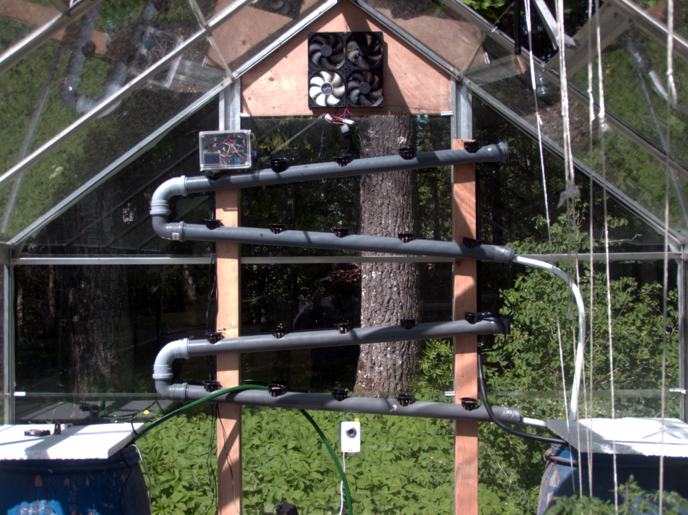
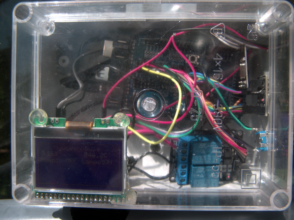
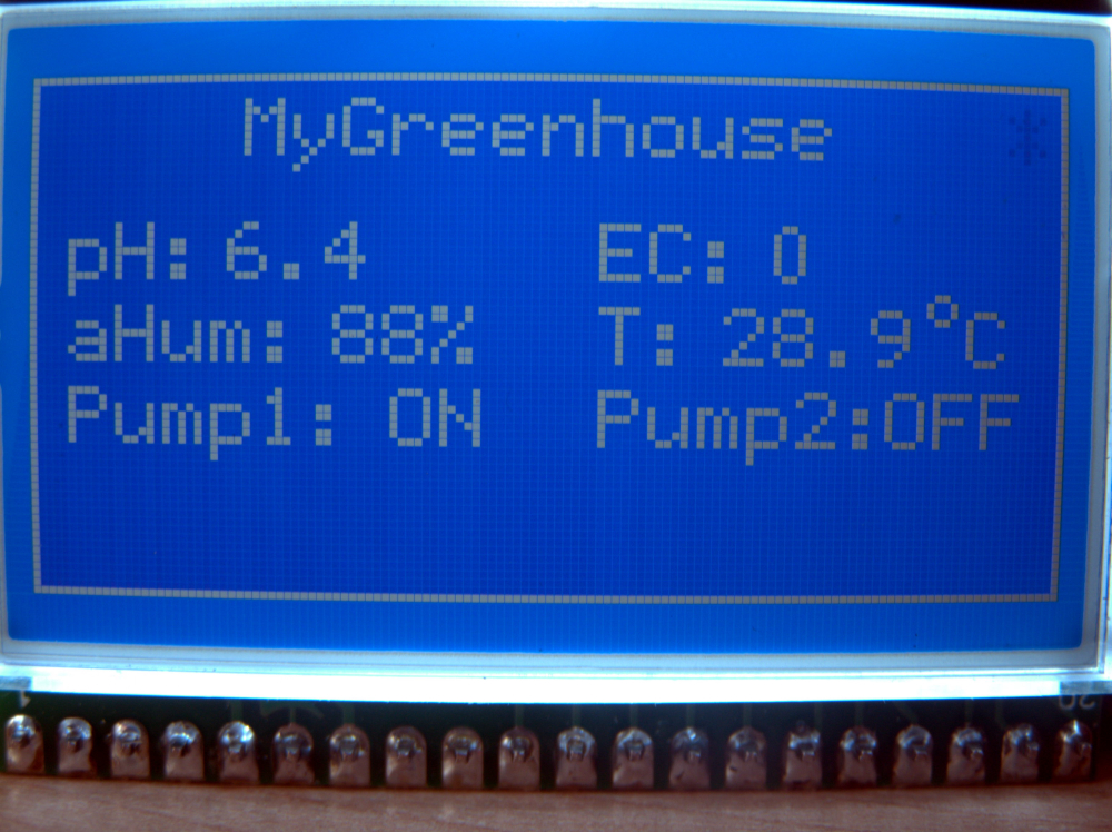
Navigation

    • Register
    • Login
    • OpenHardware.io
    • Categories
    • Recent
    • Tags
    • Popular
    1. Home
    2. Thucar
    3. Best
    • Profile
    • Following
    • Followers
    • Topics
    • Posts
    • Best
    • Groups

    Best posts made by Thucar

    • RE: MY_GATEWAY_TINYGSM

      It is alive!!!

      MQTT Client gateway with GSM modems and ESP8266 as a modem seems to be working as intended.

      To replicate, do this:

      • Install the TinyGSM library
      • Use this MyGatewayTransportMQTTClient.cpp
      /*
      * The MySensors Arduino library handles the wireless radio link and protocol
      * between your home built sensors/actuators and HA controller of choice.
      * The sensors forms a self healing radio network with optional repeaters. Each
      * repeater and gateway builds a routing tables in EEPROM which keeps track of the
      * network topology allowing messages to be routed to nodes.
      *
      * Created by Henrik Ekblad <henrik.ekblad@mysensors.org>
      * Copyright (C) 2013-2017 Sensnology AB
      * Full contributor list: https://github.com/mysensors/Arduino/graphs/contributors
      *
      * Documentation: http://www.mysensors.org
      * Support Forum: http://forum.mysensors.org
      *
      * This program is free software; you can redistribute it and/or
      * modify it under the terms of the GNU General Public License
      * version 2 as published by the Free Software Foundation.
      */
      
      
      // Topic structure: MY_MQTT_PUBLISH_TOPIC_PREFIX/NODE-ID/SENSOR-ID/CMD-TYPE/ACK-FLAG/SUB-TYPE
      
      #include "MyGatewayTransport.h"
      
      #if defined MY_CONTROLLER_IP_ADDRESS
      IPAddress _brokerIp(MY_CONTROLLER_IP_ADDRESS);
      #endif
      
      #if defined(MY_IP_ADDRESS)
      IPAddress _MQTT_clientIp(MY_IP_ADDRESS);
      #if defined(MY_IP_GATEWAY_ADDRESS)
      IPAddress _gatewayIp(MY_IP_GATEWAY_ADDRESS);
      #elif defined(MY_GATEWAY_ESP8266) /* Elif part of MY_IP_GATEWAY_ADDRESS */
      // Assume the gateway will be the machine on the same network as the local IP
      // but with last octet being '1'
      IPAddress _gatewayIp(_MQTT_clientIp[0], _MQTT_clientIp[1], _MQTT_clientIp[2], 1);
      #endif /* End of MY_IP_GATEWAY_ADDRESS */
      #if defined(MY_IP_SUBNET_ADDRESS)
      IPAddress _subnetIp(MY_IP_SUBNET_ADDRESS);
      #elif defined(MY_GATEWAY_ESP8266) /* Elif part of MY_IP_SUBNET_ADDRESS */
      IPAddress _subnetIp(255, 255, 255, 0);
      #endif /* End of MY_IP_SUBNET_ADDRESS */
      #endif /* End of MY_IP_ADDRESS */
      
      #if defined(MY_GATEWAY_ESP8266)
      #define EthernetClient WiFiClient
      #elif defined(MY_GATEWAY_LINUX)
      // Nothing to do here
      #else
      uint8_t _MQTT_clientMAC[] = { MY_MAC_ADDRESS };
      #endif /* End of MY_GATEWAY_ESP8266 */
      
      #ifdef MY_GATEWAY_TINYGSM
      #include <TinyGsmClient.h>
      static TinyGsm modem(SerialAT);
      static TinyGsmClient _MQTT_gsmClient(modem);
      static PubSubClient _MQTT_client(_MQTT_gsmClient);
      #if defined(MY_GSM_BAUDRATE)
      uint32_t rate = MY_GSM_BAUDRATE;
      #else
      uint32_t rate = 0;
      #endif
      #else
      static EthernetClient _MQTT_ethClient;
      static PubSubClient _MQTT_client(_MQTT_ethClient);
      #endif /* End of MY_GATEWAY_TINYGSM */
      
      
      static bool _MQTT_connecting = true;
      static bool _MQTT_available = false;
      static MyMessage _MQTT_msg;
      
      bool gatewayTransportSend(MyMessage &message)
      {
      	if (!_MQTT_client.connected()) {
      		return false;
      	}
      	setIndication(INDICATION_GW_TX);
      	char *topic = protocolFormatMQTTTopic(MY_MQTT_PUBLISH_TOPIC_PREFIX, message);
      	GATEWAY_DEBUG(PSTR("GWT:TPS:TOPIC=%s,MSG SENT\n"), topic);
      #if defined(MY_MQTT_CLIENT_PUBLISH_RETAIN)
      	bool retain = mGetCommand(message) == C_SET ||
      	              (mGetCommand(message) == C_INTERNAL && message.type == I_BATTERY_LEVEL);
      #else
      	bool retain = false;
      #endif /* End of MY_MQTT_CLIENT_PUBLISH_RETAIN */
      	return _MQTT_client.publish(topic, message.getString(_convBuffer), retain);
      }
      
      void incomingMQTT(char* topic, uint8_t* payload, unsigned int length)
      {
      	GATEWAY_DEBUG(PSTR("GWT:IMQ:TOPIC=%s, MSG RECEIVED\n"), topic);
      	_MQTT_available = protocolMQTTParse(_MQTT_msg, topic, payload, length);
      }
      
      bool reconnectMQTT(void)
      {
      	GATEWAY_DEBUG(PSTR("GWT:RMQ:MQTT RECONNECT\n"));
      	// Attempt to connect
      	if (_MQTT_client.connect(MY_MQTT_CLIENT_ID
      #if defined(MY_MQTT_USER) && defined(MY_MQTT_PASSWORD)
      	                         , MY_MQTT_USER, MY_MQTT_PASSWORD
      #endif
      	                        )) {
      		GATEWAY_DEBUG(PSTR("GWT:RMQ:MQTT CONNECTED\n"));
      
      		// Send presentation of locally attached sensors (and node if applicable)
      		presentNode();
      
      		// Once connected, publish an announcement...
      		//_MQTT_client.publish("outTopic","hello world");
      		// ... and resubscribe
      		_MQTT_client.subscribe(MY_MQTT_SUBSCRIBE_TOPIC_PREFIX "/+/+/+/+/+");
      		return true;
      	}
      	return false;
      }
      
      bool gatewayTransportConnect(void)
      {
      #if defined(MY_GATEWAY_ESP8266)
      	while (WiFi.status() != WL_CONNECTED) {
      		wait(500);
      		GATEWAY_DEBUG(PSTR("GWT:TPC:CONNECTING...\n"));
      	}
      	GATEWAY_DEBUG(PSTR("GWT:TPC:IP=%s\n"),WiFi.localIP().toString().c_str());
      #elif defined(MY_GATEWAY_LINUX) /* Elif part of MY_GATEWAY_ESP8266 */
      #if defined(MY_IP_ADDRESS)
      	_MQTT_ethClient.bind(_MQTT_clientIp);
      #endif /* End of MY_IP_ADDRESS */
      #elif defined(MY_GATEWAY_TINYGSM)
          GATEWAY_DEBUG(PSTR("GWT:TPC:IP=%s\n"), modem.getLocalIP().c_str());
      #else /* Else part of MY_GATEWAY_ESP8266 */
      #if defined(MY_IP_ADDRESS)
      	Ethernet.begin(_MQTT_clientMAC, _MQTT_clientIp);
      #else /* Else part of MY_IP_ADDRESS */
      	// Get IP address from DHCP
      	if (!Ethernet.begin(_MQTT_clientMAC)) {
      		GATEWAY_DEBUG(PSTR("!GWT:TPC:DHCP FAIL\n"));
      		_MQTT_connecting = false;
      		return false;
      	}
      #endif /* End of MY_IP_ADDRESS */
      	GATEWAY_DEBUG(PSTR("GWT:TPC:IP=%" PRIu8 ".%" PRIu8 ".%" PRIu8 ".%" PRIu8 "\n"),
      	              Ethernet.localIP()[0],
      	              Ethernet.localIP()[1], Ethernet.localIP()[2], Ethernet.localIP()[3]);
      	// give the Ethernet interface a second to initialize
      	delay(1000);
      #endif /* End of MY_GATEWAY_ESP8266 */
      	return true;
      }
      
      bool gatewayTransportInit(void)
      {
      	_MQTT_connecting = true;
      
      #if defined(MY_GATEWAY_TINYGSM)
      
      #if defined(MY_GSM_RX) && defined(MY_GSM_TX)
      	SoftwareSerial SerialAT(MY_GSM_RX, MY_GSM_TX);
      #else
      	// TODO: Needs sanity checks
      #endif
      
      #if !defined(MY_GSM_BAUDRATE)
      	rate = TinyGsmAutoBaud(SerialAT);
      #endif
      
      	SerialAT.begin(rate);
      	delay(3000);
      
      	modem.restart();
      
      #if defined(MY_GSM_PIN) && !defined(TINY_GSM_MODEM_ESP8266)
      	modem.simUnlock(MY_GSM_PIN);
      #endif
      
      #ifndef TINY_GSM_MODEM_ESP8266
      	if (!modem.waitForNetwork()) {
      		GATEWAY_DEBUG(PSTR("!GWT:TIN:GPRS FAIL\n"));
      		while (true);
      	}
      	GATEWAY_DEBUG(PSTR("GWT:TIN:GPRS OK\n"));
      
      	if (!modem.gprsConnect(MY_GSM_APN, MY_GSM_USR, MY_GSM_PSW)) {
      		GATEWAY_DEBUG(PSTR("!GWT:TIN:APN FAIL\n"));
      		while (true);
      	}
      	GATEWAY_DEBUG(PSTR("GWT:TIN:APN OK\n"));
      	delay(1000);
      #else
          if (!modem.networkConnect(MY_GSM_SSID, MY_GSM_PSW)) {
              GATEWAY_DEBUG(PSTR("!GWT:TIN:WIFI AP FAIL\n"));
              while (true);
            }
            GATEWAY_DEBUG(PSTR("GWT:TIN:WIFI AP OK\n"));
            delay(1000);
      #endif
      
      #endif /* End of MY_GATEWAY_TINYGSM */
      
      #if defined(MY_CONTROLLER_IP_ADDRESS)
      	_MQTT_client.setServer(_brokerIp, MY_PORT);
      #else
      	_MQTT_client.setServer(MY_CONTROLLER_URL_ADDRESS, MY_PORT);
      #endif /* End of MY_CONTROLLER_IP_ADDRESS */
      
      	_MQTT_client.setCallback(incomingMQTT);
      
      #if defined(MY_GATEWAY_ESP8266)
      	// Turn off access point
      	WiFi.mode(WIFI_STA);
      #if defined(MY_ESP8266_HOSTNAME)
      	WiFi.hostname(MY_ESP8266_HOSTNAME);
      #endif /* End of MY_ESP8266_HOSTNAME */
      #if defined(MY_IP_ADDRESS)
      	WiFi.config(_MQTT_clientIp, _gatewayIp, _subnetIp);
      #endif /* End of MY_IP_ADDRESS */
      #ifndef MY_ESP8266_BSSID
      #define MY_ESP8266_BSSID NULL
      #endif
      	(void)WiFi.begin(MY_ESP8266_SSID, MY_ESP8266_PASSWORD, 0, MY_ESP8266_BSSID);
      #endif /* End of MY_GATEWAY_ESP8266 */
      
      	gatewayTransportConnect();
      
      	_MQTT_connecting = false;
      	return true;
      }
      
      bool gatewayTransportAvailable(void)
      {
      	if (_MQTT_connecting) {
      		return false;
      	}
      	//keep lease on dhcp address
      	//Ethernet.maintain();
      	if (!_MQTT_client.connected()) {
      		//reinitialise client
      		if (gatewayTransportConnect()) {
      			reconnectMQTT();
      		}
      		return false;
      	}
      	_MQTT_client.loop();
      	return _MQTT_available;
      }
      
      MyMessage & gatewayTransportReceive(void)
      {
      	// Return the last parsed message
      	_MQTT_available = false;
      	return _MQTT_msg;
      }
      
      
      • Define these in your gateway sketch:
      #define MY_GATEWAY_MQTT_CLIENT
      // Enable gateway ethernet module type
      #define MY_GATEWAY_TINYGSM
      
      // Define the GSM modem. See TinyGSM documentation for full list
      //#define TINY_GSM_MODEM_ESP8266
      #define TINY_GSM_MODEM_A6
      #define MY_GSM_APN "internet" // your mobile providers APN
      #define MY_GSM_USR "" // Leave empty if not used
      #define MY_GSM_PIN "" // Leave empty if not used
      #define MY_GSM_PSW "" // This is either your mobile providers password or WiFi password, depending if you are using the ESP8266 or a GSM modem
      #define MY_GSM_SSID ""
      
      // Use Hardware Serial on Mega, Leonardo, Micro
      #define SerialAT Serial1
      #define MQTT_VERSION MQTT_VERSION_3_1 // I apparently need this to be able to run mosquitto
      
      posted in Development
      Thucar
      Thucar
    • RE: MySensors Hydroponics Greenhouse project

      A long overdue update.

      In the end I basically ended up using a GSM gateway with a LCD and couple sensors (air temperature and air humidity) and two relays. The relays control my Dutch bucket system pump and ventilation fans.

      As a separate sensor I'm using a Z-Wave multisensor to keep track of nursery temperatures and lux levels.

      The pH meter module did arrive but I do not feel comfortable keeping it submerged in the nutrient solution at all times so I've been just taking a sample of the nutrient solution from the tank after mixing a new batch, and testing it indoors, at the computer.

      As for the EC meter, I failed to get any of the "arduino only" examples to produce reliable readings. So I've ordered 5 PCB's for this thing: https://www.sparkyswidgets.com/portfolio-item/miniec-i2c-ec-interface/
      Once they arrive, I'll see if I can get more reliable results with a separate module.

      So far the whole thing has been running almost perfectly. The only drawback is an occasional reboot of the gateway when switching off the Dutch bucket system pump. I'm using two separate power sources for Arduino and the pump, Added a 1000uF cap to the Arduino power rail and a flyback diode across the pumps power lines. Still getting that reboot about 50% of the time.

      Some pics to wrap up my rant.
      PS. Yes, that's a webcam in my greenhouse. It's taking hourly snapshots for a timelapse 🙂

      0_1526815202323_P5201185_v1.JPG
      My NFT rails for herbs. A good eye can spot some dill, basil and cilantro plants in there.
      0_1526815222254_P5201186_v1.JPG
      That's my "Nursery" - an old fish tank I can cover with a piece of glass when night temps dip below 10C
      0_1526815238126_P5201187_v1.JPG
      That's my Fibaro Motion sensor. An easy way to get some essential readings. Like the length of day, hours of sunlight, temperature.
      0_1526815313192_P5201191_v1.JPG
      This is my ratsnest. I should have moved the relays to a separate enclosure further away. Right now I think the arc when breaking contact is what's causing an EMP pulse and rebooting my Mega.
      0_1526815355995_P5201190_v1.JPG
      Ventilation fans. The temps soared to high 40's and low 50's with door and both ceiling hatches wide open. The fans kick in when air temp reaches 25C
      0_1526815372094_P5201193_v1.JPG

      posted in My Project
      Thucar
      Thucar
    • RE: What did you build today (Pictures) ?

      Built half of my dutch bucket system. Namely the drain part. Irrigation to follow.

      0_1523760716315_P4141131_v1.JPG 0_1523760724731_P4141133_v1.JPG 0_1523760736892_P4141140_v1.JPG 0_1523760744189_P4141141_v1.JPG
      0_1523760676911_P4141144_v1.JPG

      posted in General Discussion
      Thucar
      Thucar
    • MySensors Hydroponics Greenhouse project

      So, I’ve been using MySensors all around the house as test devices. I also set up a solar powered Beehive node last autumn, to monitor my hives conditon (went a bit overboard with a total of 6 temp sensors and a humidity sensor.) By the way, the sensors ended up saving my bees.

      Anyhow, I’m now tackling my biggest project yet. A 6.6m2 greenhouse which I’ll be converting to hydroponics. 44 dutch buckets for tomatos, cucumbers, radishes and a vertical NFT system for herbs.

      The goal for now is to monitor the following:

      • Nutrient solution pH levels - a kit from Aliexpress
      • Nutrient solution EC(parts per million) - a probe from Aliexpress
      • Nutrient solution temperature - NTC thermistor 10k
      • Nutrient solution level in the tank - ultrasonic transceiver
      • Dutch bucket substrate moisture - Moisture pitchfork
      • Ambient air temperature - NTC thermistor 10k
      • Ambient air relative humidity - SHT21
      • Ambient light levels - BH1750
      • Some way to monitor if the water is flowing?

      As for the actuators, my greenhouse ventilation windows are operated by sylinders with heat expanding gas. So I will have no direct control over them. The only thing I’m thinking that needs operating, are the circulation pumps. I’ll be using a simple dual relay module for that at first with the possibility of switching to a mosfet later on, as it seems the pumps might respond well to a variable input voltage and thus, allow me to fine tune the rate of liquid flow.

      The brains for the operation will be Arduino Mega with a sensors shield. I only later realized it's an Uno shield, but luckily the pinouts match and I should be able to use it without much hassle. Might actually be a good thing because I can use a dedicated header for the radio and whatever else I need to connect to the 22+ ports.

      posted in My Project
      Thucar
      Thucar
    • RE: MySensors Hydroponics Greenhouse project

      Got some work done on the hardware side of things. Drainage is done, next up is feed part.

      0_1523760716315_P4141131_v1.JPG
      0_1523760999160_P4141137_v1.JPG 0_1523761006369_P4141139_v1.JPG
      0_1523760989088_P4141136_v1.JPG 0_1523760724731_P4141133_v1.JPG 0_1523760736892_P4141140_v1.JPG 0_1523760744189_P4141141_v1.JPG
      0_1523760676911_P4141144_v1.JPG

      posted in My Project
      Thucar
      Thucar
    • RE: MySensors Hydroponics Greenhouse project

      A quick video update: https://youtu.be/vnUFV_amSPQ
      The tomatos and peas are trying to go through the roof. Cucumbers are close to follow. They are all aiming for the ventilation hatches - I think they are planning a grand escape...

      The NFT system pump stopped working coupe weeks after setting it up. Have not gotten around to ordering a new pump. That will be a project for next year.

      posted in My Project
      Thucar
      Thucar
    • RE: Secondary ESP8266 gateway

      Guess we can mark this one down to iffy PA/LNA modules. After verifying that a repeater solves the problem, I replaced both, the gateway and beehive sensor radios out for regular nrf24l01's. At first I had a repeater as well in between the two, but after making sure the communication was there, I disconnected the repeater.

      And lo and behold - the communication still works fine. So now I modified the gateway radio by cutting the pcb antenna trace and soldering in a SMA connector. Now I have a high DBi wireless antenna attached to the gateway and no more reception issues.

      posted in Troubleshooting
      Thucar
      Thucar
    • MY_GATEWAY_TINYGSM

      I've been toying with this idea for a while now. Have attempted it once before, got stuck and am trying again now.

      The idea is simple - have a GSM/GPRS modem connected to your gateway so you can set it up in a remote location, stick a SIM card in it and be done.

      I chose the TinyGSM library due to its light weight and active maintenance by the author. As an added benefit, the library supports the ESP8266 as well. So you can have a beefy arduino with plenty of IOs as your Gateway and have the ESP just do your wireless networking for you.

      Supported modems

      • SIMCom SIM800 series (SIM800A, SIM800C, SIM800L, SIM800H, SIM808, SIM868)
      • SIMCom SIM900 series (SIM900A, SIM900D, SIM908, SIM968)
      • AI-Thinker A6, A6C, A7, A20
      • U-blox SARA U201 (alpha)
      • ESP8266 (AT commands interface, similar to GSM modems)
      • Digi XBee WiFi and Cellular (using XBee command mode)
      • Neoway M590

      More modems may be supported later:

      • Quectel M10, M95, UG95
      • SIMCom SIM5320, SIM5360, SIM5216, SIM7xxx
      • Telit GL865
      • ZTE MG2639
      • Hi-Link HLK-RM04

      Right now I'm at a point where I can get the code to compile, the modem gets initialized, connection to the internet is achieved and in Client mode, the GW tries to connect to the predefined address/port.

      Unfortunately I have yet to find a controller that allows incoming gateway connections, so I have not managed to test it. And my network contract on the SIM does not have static IP or open ports, so can't test it as a regular server.

      Working on trying to set up a MQTT gateway now. With this nasty flu I have, it's not going too smoothly.

      i'm doing my testing/development here: https://github.com/thucar/MySensors

      posted in Development
      Thucar
      Thucar
    • RE: MySensors Hydroponics Greenhouse project

      Update:
      LCD + rotary click encoder working
      ArduinoMenu4 in place and easily expandable.
      Relay control works 100%
      EC/ppm measurement in place, not yet 100% working
      SHT21 code in place, can confirm if working or not once the darn thing arrives

      Some eye candy:
      0_1521972359235_P3251110_v1.JPG0_1521972941808_P3251111_v1.JPG
      0_1521972951209_P3251112_v1.JPG 0_1521972959027_P3251113_v1.JPG 0_1521972966435_P3251114_v1.JPG

      posted in My Project
      Thucar
      Thucar
    • RE: Secondary ESP8266 gateway

      The tin foil wrap tip should definitely be mentioned on the radio page. That trick really works wonders. I used ventilation aluminum foil tape. The glue on it acts as insulation so no need to use food wrap. It's also thicker than regular food grade tin foil and it being a tape makes it super easy to use.

      posted in Troubleshooting
      Thucar
      Thucar
    • RE: What did you build today (Pictures) ?

      0_1521972359235_P3251110_v1.JPG

      posted in General Discussion
      Thucar
      Thucar
    • RE: GPS and GSM

      How come? Using a TinyGSM example sketch I can connect to the internet, get an IP address, connect to my MQTT broker and push/read messages. So I was thinking all I need to do is use the TinyGSM library to set up an Internet connection. Then use the GatewayXXXXMQTTClient sketch to handle everything else. Pretty much like with Ethernet or ESP8266 versions of the gateway.

      posted in Development
      Thucar
      Thucar
    • RE: MySensors Hydroponics Greenhouse project

      This is where I'm at right now. Support for 2 relays with push buttons, light level and soil moisture measurements. Customizable measurement interval for entire device and each sensor individually. Also a change threshold (a change greater than given threshold in two consecutive readings triggers an immediate report).

      Everything is running off interrupts to ensure smooth operation.
      NB! I have not yet managed to do live tests with the BH1750 as it has not yet arrived.

      Next up are the temperature sensors and EC meter. Or whatever sensor will be the next to arrive.

      /**
       * The MySensors Arduino library handles the wireless radio link and protocol
       * between your home built sensors/actuators and HA controller of choice.
       * The sensors forms a self healing radio network with optional repeaters. Each
       * repeater and gateway builds a routing tables in EEPROM which keeps track of the
       * network topology allowing messages to be routed to nodes.
       *
       * Created by Henrik Ekblad <henrik.ekblad@mysensors.org>
       * Copyright (C) 2013-2015 Sensnology AB
       * Full contributor list: https://github.com/mysensors/Arduino/graphs/contributors
       *
       * Documentation: http://www.mysensors.org
       * Support Forum: http://forum.mysensors.org
       *
       * This program is free software; you can redistribute it and/or
       * modify it under the terms of the GNU General Public License
       * version 2 as published by the Free Software Foundation.
       *
       *******************************
       *
       * REVISION HISTORY
       * Version 1.0 - Rait Lotamõis
       *
       * DESCRIPTION
       * First iteration of a Hydroponic greenhouse controller sketch.
       * Supports: 
       * 2 relays with individual push buttons
       * BH1750 Light sensor
       * Moisture sensor
       * 
       */
      
      // Enable debug prints to serial monitor
      #define MY_DEBUG
      
      // Enable and select radio type attached
      #define MY_RADIO_NRF24
      //#define MY_RADIO_RFM69
      
      // Enable repeater functionality for this node
      #define MY_REPEATER_FEATURE
      
      #include <MySensors.h>
      #include <Vcc.h>
      #include <ResponsiveAnalogRead.h>
      #include <SPI.h>
      #include <BH1750.h>
      #include <Wire.h>
      #include <TimerOne.h>
      
      // Measurement and reporting settings
      #define REPORT_INTERVAL 600 // define report interval in seconds for all sensors. This is when a full report is sent, no matter what
      #define MOI_MEASUREMENT_INTERVAL 10 // Time in seconds, between consecutive measurements
      #define MOI_REPORT_THRESHOLD 5 // The difference in % between two consecutive readings to send an immediate report
      #define LUX_MEASUREMENT_INTERVAL 15 // Time in seconds, between consecutive measurements
      #define LUX_REPORT_THRESHOLD 100 // The difference in Lux between two consecutive readings to send an immediate report
      
      // Relay settings. TODO: Make it easy to use more than two relays
      #define RLY_PIN_1  4
      #define RLY_PIN_2  5
      #define RLY_BTN_1 2 // Pin to use for a pushbutton switch. NB! Needs an interrupt pin
      #define RLY_BTN_2 3 // Pin to use for a pushbutton switch. NB! Needs an interrupt pin
      #define RLY_ON 0  // GPIO value to write to turn on attached relay
      #define RLY_OFF 1 // GPIO value to write to turn off attached relay
      #define RLY_ID_1 1 // MySensors Child ID
      #define RLY_ID_2 2 // MySensors Child ID
      
      // Soil Moisture settings
      #define MOI_SENSE_PIN A0 // Analog pin connecting to the probe
      #define MOI_POWER_PIN 6 // Pin for powering the humidity sensor
      #define MOI_0_PERCENT 0 // Probe output voltage at 0% moisture
      #define MOI_100_PERCENT 2.5 // Probe output voltage in a glass of water
      #define MOI_ID 3 // MySensors Child ID
      
      // Lux sensor settings
      #define LUX_ID 0 // MySensors Child ID
      
      // General settings
      #define VCC_VOLTAGE_READ 5.0 // Actual supply voltage going to the VCC. Use a multimeter to check
      #define VCC_VOLTAGE_REPORTED 4.97 // Set this to the same as above for your first boot. Then insert the value reported in the Serial window during boot
      #define ONE_SECOND_IN_MICROS 500000 // Depends on your crystal. 8MHz crystal:500000, 16MHz crystal:1000000, etc. If your time intervals are off, this is the reason
      
      // Soil Moisture variables
      float cal0 = MOI_0_PERCENT; 
      float cal100 = MOI_100_PERCENT; 
      ResponsiveAnalogRead analogMoi(MOI_SENSE_PIN, false);
      MyMessage msgMoi(0,V_LEVEL);
      float lastMoisture = 0;
      
      // Relay variables
      MyMessage msgRly(0,V_STATUS);
      bool rlyState1 = false;
      bool rlyState2 = false;
      
      // Lux sensor variables
      BH1750 luxSensor;
      MyMessage msgLux(0, V_LIGHT_LEVEL);
      uint16_t lastLux = 0;
      
      // VCC Monitoring for calculations
      const float VccCorrection = VCC_VOLTAGE_READ/VCC_VOLTAGE_REPORTED; 
      Vcc vcc(VccCorrection);
      
      // General variables
      bool receivedConfig = false;
      bool metric = true;
      long reportTimer = REPORT_INTERVAL;
      long moiTimer = MOI_MEASUREMENT_INTERVAL;
      long luxTimer = LUX_MEASUREMENT_INTERVAL;
      const unsigned long debounceTime = 50;
      
      void before()
      {
      
      }
      
      void setup()
      {
        // Initialize the timer interrupt for sending sensor reports
        Timer1.initialize(ONE_SECOND_IN_MICROS); 
        Timer1.attachInterrupt(countDownOneSecond);
      
        // Initialize and set relays to last known states (using eeprom storage)
        pinMode(RLY_PIN_1, OUTPUT);
        pinMode(RLY_PIN_2, OUTPUT);
        rlyState1 = loadState(RLY_ID_1);
        rlyState2 = loadState(RLY_ID_2);
        digitalWrite(RLY_PIN_1, rlyState1?RLY_ON:RLY_OFF);
        digitalWrite(RLY_PIN_2, rlyState2?RLY_ON:RLY_OFF);
      
        // Set the interrupts for relay buttons
        pinMode(RLY_BTN_1, INPUT_PULLUP);
        pinMode(RLY_BTN_2, INPUT_PULLUP);
        attachInterrupt(digitalPinToInterrupt(RLY_BTN_1), toggleRly1, FALLING);
        attachInterrupt(digitalPinToInterrupt(RLY_BTN_2), toggleRly2, FALLING);
        
        // Initialize Soil Moisture power pin
        pinMode(MOI_POWER_PIN, OUTPUT);
        digitalWrite(MOI_POWER_PIN, LOW);
      
        // Initialize the Lux sensor
        luxSensor.begin();
      
        // Take and report voltage readings
      #ifdef MY_DEBUG
        Serial.print("Measuring VCC voltage as: ");
        Serial.print(vcc.Read_Volts());
        Serial.println("V");
      #endif
      }
      
      void presentation()
      {
        // Send the sketch version information to the gateway and Controller
        sendSketchInfo("Greenhouse Node", "0.3");
      
        // Register Relays
        present(RLY_ID_1, S_BINARY);
        present(RLY_ID_2, S_BINARY);
      
        // Register Soil Moisture sensor
        present(MOI_ID, S_MOISTURE);
        
        // Register Lux sensor
        present(LUX_ID, S_LIGHT_LEVEL);
      
      }
      
      
      void loop()
      {
      
        // Update the relay outputs
        updateRelays();
        
        // Get Soil Moisture levels if it is time
        if (moiTimer == 0){
      #ifdef MY_DEBUG
          Serial.print("Taking Moisture measurements: ");
      #endif
          readMoisture();
      #ifdef MY_DEBUG
          Serial.print(lastMoisture);
          Serial.println("%");
      #endif
          moiTimer = MOI_MEASUREMENT_INTERVAL;
        }
      
        // Get Lux level if it is time
        if (luxTimer == 0){
      #ifdef MY_DEBUG
          Serial.print("Taking Lux measurements: ");
      #endif
          readLux();
      #ifdef MY_DEBUG
          Serial.print(lastLux);
          Serial.println("lux");
      #endif
          luxTimer = LUX_MEASUREMENT_INTERVAL;
        }
      
        // Send reports it if is time
        if (reportTimer == 0){
      #ifdef MY_DEBUG
          Serial.println("Sending reports.");
      #endif
          sendReports();
          reportTimer = REPORT_INTERVAL;
        }
        
      }
      
      void receive(const MyMessage &message)
      {
        if (message.isAck()) {
      #ifdef MY_DEBUG
           Serial.println("This is an ack from gateway");
      #endif
           return;
        }
        // We only expect one type of message from controller. But we better check anyway.
        if (message.type==V_STATUS) {
            // Change relay state
            int outputPin = (message.sensor == RLY_ID_1)?RLY_PIN_1:RLY_PIN_2;
            digitalWrite(outputPin, message.getBool()?RLY_ON:RLY_OFF);
            // Store state in eeprom
            saveState(message.sensor, message.getBool());
      #ifdef MY_DEBUG
            // Write some debug info
            Serial.print("Incoming change for relay:");
            Serial.print(message.sensor);
            Serial.print(", New status: ");
            Serial.println(message.getBool());
      #endif
            // Update the state variables
            rlyState1 = loadState(RLY_ID_1);
            rlyState2 = loadState(RLY_ID_2);
        }
      }
      
      // Check if a button has been pressed, meaning we should flip the relay
      void updateRelays(){
        bool oldState1 = loadState(RLY_ID_1);
        bool oldState2 = loadState(RLY_ID_2);
      
        if (oldState1 != rlyState1){
          digitalWrite(RLY_PIN_1, rlyState1?RLY_ON:RLY_OFF);
          saveState(RLY_ID_1, rlyState1?true:false);
          send(msgRly.setSensor(RLY_ID_1).set(rlyState1?true:false), false);
        }
      
        if (oldState2 != rlyState2){
          digitalWrite(RLY_PIN_2, rlyState2?RLY_ON:RLY_OFF);
          saveState(RLY_ID_2, rlyState2?true:false);
          send(msgRly.setSensor(RLY_ID_2).set(rlyState2?true:false), false);
        }
      }
      
      // Send all reports using last known values
      void sendReports(){
        
        // Send Lux
        send(msgLux.set(lastLux));
        
        // Send Moisture
        send(msgMoi.set(lastMoisture,1));
      }
      
      // Get the light level values
      void readLux(){
        uint16_t lux = luxSensor.readLightLevel();
        // Check if the difference between previous reading and this one is enough to warrant an immediate report
        if ((abs(lux-lastLux) > LUX_REPORT_THRESHOLD) && reportTimer > 0){
          send(msgLux.set(lux));
        }
        lastLux = lux;
      }
      
      // get the soil moisture values
      void readMoisture(){
        float v = vcc.Read_Volts();
        int aRead = readSoil();
        float voltage = (aRead * v / 1024.0);
        float moisture = voltage * 100/cal100;
        // Check if the difference between previous reading and this one is enough to warrant an immediate report
        if ((abs(moisture-lastMoisture) > MOI_REPORT_THRESHOLD) && reportTimer > 0){
          send(msgMoi.set(moisture,1));
        }
        lastMoisture = moisture;
      }
      
      // Perform the actual powering up and measurement process for Soil moisture sensor. TODO: Does it really need a separate function?
      int readSoil()
      {
        int val;
        digitalWrite(MOI_POWER_PIN, HIGH);
        delay(10);//wait 10 milliseconds
        analogMoi.update();
        val = analogMoi.getValue();
        digitalWrite(MOI_POWER_PIN, LOW);
        
        return val;
      }
      
      // Interrupt Service Routines
      // TODO: Would love to use the same ISR for both (all?) relays
      void toggleRly1(){
        static unsigned long previousStateChangeMillis = 0;
        bool pinState = digitalRead(RLY_BTN_1);
        if (pinState == LOW) { // only falling events
          if ((millis() - previousStateChangeMillis) > debounceTime) { // debounce
            rlyState1 = !rlyState1;
          }
        }
        previousStateChangeMillis = millis();
      }
      
      void toggleRly2(){
        static unsigned long previousStateChangeMillis = 0;
        bool pinState = digitalRead(RLY_BTN_2);
        if (pinState == LOW) { // only falling events
          if ((millis() - previousStateChangeMillis) > debounceTime) { // debounce
            rlyState2 = !rlyState2;
          }
        }
        previousStateChangeMillis = millis();
      }
      
      void countDownOneSecond(void) {
        if (moiTimer > 0){
          moiTimer--;
        }
        if (luxTimer > 0){
          luxTimer--;
        }
        if (reportTimer > 0) {
          reportTimer--;
        }
      }
      
      posted in My Project
      Thucar
      Thucar
    • RE: Have anyone experienced MySensors gateway with GPRS(MQTT)?

      @jkandasa I just finished a Gateway build with TinyGSM. You can find it here: https://www.openhardware.io/view/567/MySensors-GSM-Gateway

      posted in General Discussion
      Thucar
      Thucar
    • RE: GPS and GSM

      @fhenryco for me, the benefit of the A6 is that I have one on my desk 🙂

      @gohan I'm not fixed on using a MQTT gateway. Not after learning that a regular Ethernet Gateway can be used as a Client. Actually I would very much prefer using it as an Ethernet Gateway if I can.

      So far I have not managed to get MySensors to play ball. Even though I have an internet connection up and running and a port to connect to, I'm not seeing any incoming connections. Must dig deeper.

      posted in Development
      Thucar
      Thucar
    • RE: MySensors Hydroponics Greenhouse project

      To quote the classics - “Well, that escalated quickly.”

      While waiting for the sensors to arrive, I started mulling over the entire project in my head. And I started thinking about scaling. My greenhouse is only 3 meters long but my parents greenhouse is almost 30 meters. Routing wires for soil sensors around the place is no fun.

      So that got me thinking - does it need to be one node? And that in turn got me thinking - does it even have to be a node? Maybe a gateway would be the way to go?

      So this is my current plan - a GSM/Wifi gateway with the general and more power hungry components( pH, EC, relative air humidity and ambient temp, relays). The gateway would be located near the pumps, sumps and other tech in the greenhouse.

      Then the rest of the greenhouse can be filled with any number of sensors to monitor soil moisture, temperature and light levels at different places.

      GSM gateway is almost finished, hopefully I can wrap it up tomorrow.

      And as a final touch, I realized a controller of that kind of functionality could use a local user input. So it’s going to have a LCD and some buttons for set-up and things like starting/stopping pumps for maintenance.

      posted in My Project
      Thucar
      Thucar
    • RE: Will a NRF24L01+PA+LNA help with my signal problems

      @Greymarvel for a gateway I would suggest using a shielded version of the NRF24L01+PA+LNA as well as this supply adapter

      I was having world of issues with my setup until I did that.

      posted in Development
      Thucar
      Thucar
    • RE: Looking for Sensor

      Hello and welcome to the forum @777upender

      Could you tell us what's your research on the topic so far? Which sensors have caught your eye and what strengths drawbacks they have in regard of your project? I'd be happy to offer my 2 cents worth in helping you narrow down the choice or add recommendations of my own to that list.

      posted in My Project
      Thucar
      Thucar
    • RE: Will a NRF24L01+PA+LNA help with my signal problems

      I has an onboard voltage reg as well as caps. So you do not need to use any additional hardware.

      posted in Development
      Thucar
      Thucar
    • RE: Looking for Sensor

      And what are the benefits/drawbacks of the sensor in regards of your project? So we could get a better picture of what kind of limits your project puts on the selection.
      For instance, does it not do what you need, is it not precise enough, is it too expensive?

      posted in My Project
      Thucar
      Thucar
    • RE: MY_GATEWAY_TINYGSM
      /**
       * The MySensors Arduino library handles the wireless radio link and protocol
       * between your home built sensors/actuators and HA controller of choice.
       * The sensors forms a self healing radio network with optional repeaters. Each
       * repeater and gateway builds a routing tables in EEPROM which keeps track of the
       * network topology allowing messages to be routed to nodes.
       *
       * Created by Henrik Ekblad <henrik.ekblad@mysensors.org>
       * Copyright (C) 2013-2015 Sensnology AB
       * Full contributor list: https://github.com/mysensors/Arduino/graphs/contributors
       *
       * Documentation: http://www.mysensors.org
       * Support Forum: http://forum.mysensors.org
       *
       * This program is free software; you can redistribute it and/or
       * modify it under the terms of the GNU General Public License
       * version 2 as published by the Free Software Foundation.
       *
       *******************************
       *
       * REVISION HISTORY
       * Version 1.0 - Rait Lotamõis
       *
       *
       * DESCRIPTION
       * 
       */
      
      // Enable debug prints to serial monitor
      #define MY_DEBUG
      
      // Enable and select radio type attached
      #define MY_RADIO_NRF24
      
      //Running on Mega
      #define MY_RF24_CE_PIN 49
      #define MY_RF24_CS_PIN 53
      
      // Enable gateway ethernet module type
      #define MY_GATEWAY_TINYGSM
      
      // Define the GSM modem
      #define TINY_GSM_MODEM_A6
      
      #define MY_GSM_APN "internet"
      //#define MY_GSM_USR ""
      //#define MY_GSM_PSW ""
      //#define MY_GSM_PIN "0000"
      
      // Use Hardware Serial on Mega, Leonardo, Micro
      #define SerialAT Serial3
      
      // or Software Serial on Uno, Nano
      //#define MY_GSM_RX 4
      //#define MY_GSM_TX 5
      
      // Set your modem baud rate or comment it out for auto detection
      //#define MY_GSM_BAUDRATE 115200
      
      // The port to keep open on node server mode / or port to contact in client mode
      #define MY_PORT 5003
      
      // Controller ip address. Enables client mode (default is "server" mode).
      // Also enable this if MY_USE_UDP is used and you want sensor data sent somewhere.
      //#define MY_CONTROLLER_IP_ADDRESS 192, 168, 178, 254
      #define MY_CONTROLLER_URL_ADDRESS "xxx.yyyyyyy.com"
      
      // The MAC address can be anything you want but should be unique on your network.
      // Newer boards have a MAC address printed on the underside of the PCB, which you can (optionally) use.
      // Note that most of the Ardunio examples use  "DEAD BEEF FEED" for the MAC address.
      #define MY_MAC_ADDRESS 0xDE, 0xAD, 0xBE, 0xEF, 0xFE, 0xED
      
      // Enable inclusion mode
      //#define MY_INCLUSION_MODE_FEATURE
      // Enable Inclusion mode button on gateway
      //#define MY_INCLUSION_BUTTON_FEATURE
      // Set inclusion mode duration (in seconds)
      //#define MY_INCLUSION_MODE_DURATION 60
      // Digital pin used for inclusion mode button
      //#define MY_INCLUSION_MODE_BUTTON_PIN  3
      
      // Set blinking period
      //#define MY_DEFAULT_LED_BLINK_PERIOD 300
      
      // Flash leds on rx/tx/err
      // Uncomment to override default HW configurations
      //#define MY_DEFAULT_ERR_LED_PIN 7  // Error led pin
      //#define MY_DEFAULT_RX_LED_PIN  8  // Receive led pin
      //#define MY_DEFAULT_TX_LED_PIN  9  // Transmit led pin
      
      #if defined(MY_USE_UDP)
      #include <EthernetUdp.h>
      #endif
      #include <Ethernet.h>
      #include <MySensors.h>
      
      void setup()
      {
        // Setup locally attached sensors
      }
      
      void presentation()
      {
        // Present locally attached sensors here
      }
      
      void loop()
      {
        // Send locally attached sensors data here
      }```
      posted in Development
      Thucar
      Thucar
    • RE: MySensors Hydroponics Greenhouse project

      Disconnecting the load eliminates the issue flat out.

      I think your previous question just triggered a lightbulb. While the module does have optocouplers in place, I have the VCC bridging jumper in place. So essentially Arduino is still sharing the power with relay coils. I'll install a step-down to get a 5V line from the pump power supply and use that to drive the relays. I believe that should eliminate my reboot issues.

      posted in My Project
      Thucar
      Thucar
    • RE: MQTT Gateway Network On Demand

      @neverdie because beeyards are often located nowhere near your own property. You usually negotiate with a land owner if its ok to have your bees on some corner of his land, or in a forest he owns. The actual location of the yard could be as far as 200-300km from your own house. Of course, an option would be to convince the land owner to house your gateway as well, but that adds unnecessary complications to the delicate process of negotiation 🙂

      posted in Development
      Thucar
      Thucar
    • RE: MySensors Hydroponics Greenhouse project

      Confirmed. Removing the jumper and using a power supply separate from the arduino’s has cured it from reboot issues.

      posted in My Project
      Thucar
      Thucar
    • RE: Feasibility / Brainstorm for idea of Mobile outdoor Mysensors Network

      As you will be wanting to receive the information and perform actions in the vicinity of the GW, I would go with a RPi + NodeRed + NRF24. Then switch the Raspi into Access Point mode and you'll be able to hook your phone up to it to receive notifications and control settings.
      For a GSM connection, either add a USB modem or a GSM module to the IO pins, then connect to a MQTT broker on a VPS

      That way you will only need to supply power to the Raspi and you're done.

      posted in Development
      Thucar
      Thucar
    • RE: project for some farming

      I’d look into Node-Red. It’s perfect for a simple system like that but it will be able to handle pretty much anything else he decides to throw at it down the line.

      posted in My Project
      Thucar
      Thucar