Hi,
I already use mysensors with NRF24L01 and it works well.
I would like to use mysensors with RS485 nodes but I have communication problems
I'm using an Arduino Duemilanove (yes, it's old but it still works well), an Arduino Uno compatible board and 2 RS485 modules for testing.
I used this wiring diagram: https://2.bp.blogspot.com/--MTeYYSu6nE/WViOqBi4T8I/AAAAAAAAUP8/cTphNMowJXUlAOn-oD44f1Wdd2NFrgpXgCLcBGAs/s1600/schemat%2BRS485%2BMySensors.jpg.
I have exactly the same RS485 modules.
Here is the gateway code:
// Enable debug prints to serial monitor
#define MY_DEBUG

// Enable RS485 transport layer
#define MY_RS485

// Define this to enables DE-pin management on defined pin
#define MY_RS485_DE_PIN 2

// Set RS485 baud rate to use
#define MY_RS485_BAUD_RATE 9600

// Enable this if RS485 is connected to a hardware serial port
//#define MY_RS485_HWSERIAL Serial1

// Enable serial gateway
#define MY_GATEWAY_SERIAL


// Enable inclusion mode
#define MY_INCLUSION_MODE_FEATURE
// Enable Inclusion mode button on gateway
#define MY_INCLUSION_BUTTON_FEATURE
// Set inclusion mode duration (in seconds)
#define MY_INCLUSION_MODE_DURATION 60
// Digital pin used for inclusion mode button
#define MY_INCLUSION_MODE_BUTTON_PIN  3

// Set blinking period
#define MY_DEFAULT_LED_BLINK_PERIOD 300

// Flash leds on rx/tx/err
#define MY_DEFAULT_ERR_LED_PIN 4  // Error led pin
#define MY_DEFAULT_RX_LED_PIN  5  // Receive led pin
#define MY_DEFAULT_TX_LED_PIN  6  // the PCB, on board LED

#include <MySensors.h>

void setup()
{
	// Setup locally attached sensors
}

void presentation()
{
	// Present locally attached sensors
}

void loop()
{
	// Send locally attached sensor data here
}
And the gataway log:
Terminal ready
0;255;3;0;9;0 MCO:BGN:INIT GW,CP=RSNGA---,FQ=16,REL=255,VER=2.3.2
0;255;3;0;9;5 TSM:INIT
0;255;3;0;9;7 TSF:WUR:MS=0
0;255;3;0;9;10 TSM:INIT:TSP OK
0;255;3;0;9;13 TSM:INIT:GW MODE
0;255;3;0;9;15 TSM:READY:ID=0,PAR=0,DIS=0
0;255;3;0;9;19 MCO:REG:NOT NEEDED
0;255;3;0;14;Gateway startup complete.
0;255;0;0;18;2.3.2
0;255;3;0;9;23 MCO:BGN:STP
0;255;3;0;9;29 MCO:BGN:INIT OK,TSP=1
0;255;3;0;9;33 TSM:READY:NWD REQ
0;255;3;0;9;53 ?TSF:MSG:SEND,0-0-255-255,s=255,c=3,t=20,pt=0,l=0,sg=0,ft=0,st=OK:
And the node:
// Enable debug prints to serial monitor
#define MY_DEBUG

// Enable RS485 transport layer
#define MY_RS485

// Define this to enables DE-pin management on defined pin
#define MY_RS485_DE_PIN 2

// Set RS485 baud rate to use
#define MY_RS485_BAUD_RATE 9600

// Enable this if RS485 is connected to a hardware serial port
//#define MY_RS485_HWSERIAL Serial1

#define MY_NODE_ID 20

#include <MySensors.h>

static const uint64_t UPDATE_INTERVAL = 10000;

#define CHILD_ID_VALUE 0
MyMessage msgVal(CHILD_ID_VALUE, V_VAR1);

// ----------------------------------------------------------------------------
void presentation()
{
  // Send the sketch version information to the gateway
  sendSketchInfo("RS485 Node test Sensor", "1.0");

  // Register all sensors to gw (they will be created as child devices)
  present(CHILD_ID_VALUE, S_CUSTOM, "Node RS485");
}

// ----------------------------------------------------------------------------
void setup()
{
  Serial.println( F("Arduino MySensors RS485 Node test") );    // Fonction F() permet de placer la chaine dans la mémoire eprogramme (Arduino IDE 1.0).
  analogReference(INTERNAL);
  delay(1000);
}


void loop()
{
    Serial.println( F("Loop ...") );

    // Get millis
    long ms = millis();
    Serial.print(F("Millis: "));
    Serial.println(ms);
    send(msgVal.set(ms, 1));

    // Sleep for a while to save energy
    sleep(UPDATE_INTERVAL);
}
And the node log:
__  __       ____
|  \/  |_   _/ ___|  ___ _ __  ___  ___  _ __ ___
| |\/| | | | \___ \ / _ \ `_ \/ __|/ _ \| `__/ __|
| |  | | |_| |___| |  __/ | | \__ \  _  | |  \__ \
|_|  |_|\__, |____/ \___|_| |_|___/\___/|_|  |___/
       |___/                      2.3.2

16 MCO:BGN:INIT NODE,CP=RSNNA---,FQ=16,REL=255,VER=2.3.2
26 TSM:INIT
28 TSF:WUR:MS=0
29 TSM:INIT:TSP OK
31 TSM:FPAR
49 ?TSF:MSG:SEND,255-255-255-255,s=255,c=3,t=7,pt=0,l=0,sg=0,ft=0,st=OK:
2057 !TSM:FPAR:NO REPLY
2059 TSM:FPAR
2076 ?TSF:MSG:SEND,255-255-255-255,s=255,c=3,t=7,pt=0,l=0,sg=0,ft=0,st=OK:
4084 !TSM:FPAR:NO REPLY
4086 TSM:FPAR
4104 ?TSF:MSG:SEND,255-255-255-255,s=255,c=3,t=7,pt=0,l=0,sg=0,ft=0,st=OK:
6112 !TSM:FPAR:NO REPLY
6114 TSM:FPAR
6131 ?TSF:MSG:SEND,255-255-255-255,s=255,c=3,t=7,pt=0,l=0,sg=0,ft=0,st=OK:
8139 !TSM:FPAR:FAIL
8140 TSM:FAIL:CNT=1
8142 TSM:FAIL:DIS
8144 TSF:TDI:TSL
18146 TSM:FAIL:RE-INIT
18148 TSM:INIT
18149 TSM:INIT:TSP OK
18151 TSM:FPAR
18169 ?TSF:MSG:SEND,255-255-255-255,s=255,c=3,t=7,pt=0,l=0,sg=0,ft=0,st=OK:
20178 !TSM:FPAR:NO REPLY
20180 TSM:FPAR
20199 ?TSF:MSG:SEND,255-255-255-255,s=255,c=3,t=7,pt=0,l=0,sg=0,ft=0,st=OK:
22206 !TSM:FPAR:NO REPLY
22208 TSM:FPAR
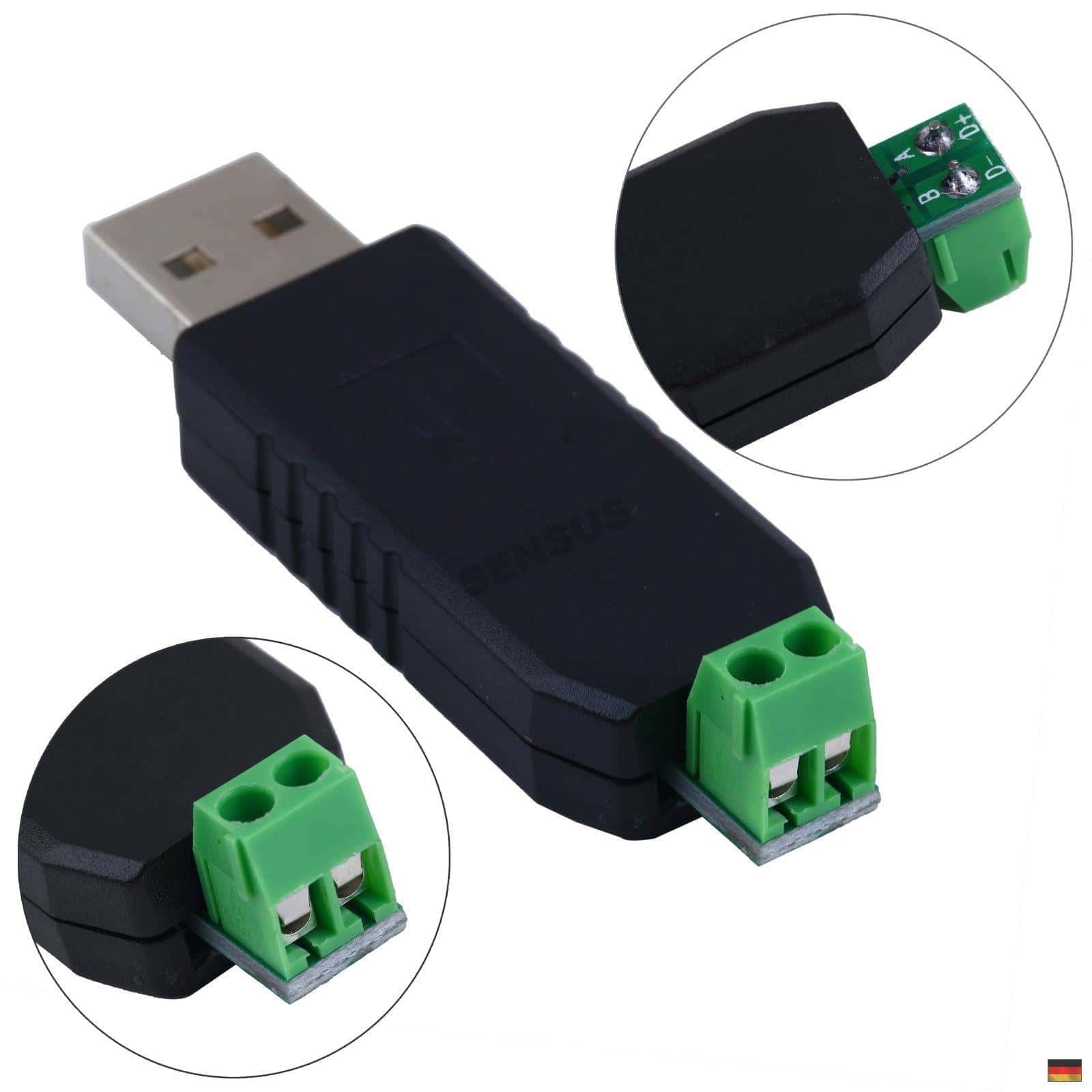
To debug, I also use this USB RS485 module: https://www.makershop.de/wp-content/uploads/2016/01/1PC-font-b-USB-b-font-to-font-b-RS485-b-font-font-b-USB-b.jpg, this one is connected to the RS485 bus and I can see with a simple python program the data sent by the node:
01 ff 00 58 07 02 ff ff ff 02 03 07 ff 03 66 04
01 ff 00 58 07 02 ff ff ff 02 03 07 ff 03 66 04
01 ff 00 58 07 02 ff ff ff 02 03 07 ff 03 66 04
01 ff 00 58 07 02 ff ff ff 02 03 07 ff 03 66 04
...
Still nothing is received on the gateway !
I have checked the wiring several times, and tested with other identical RS485 modules but still the same problem.
Would you have other tracks?
Thanks
ps: I use Arduino IDE 1.8.13 and MySensors lib 2.3.2