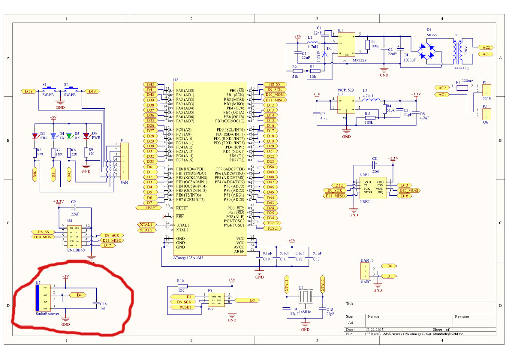
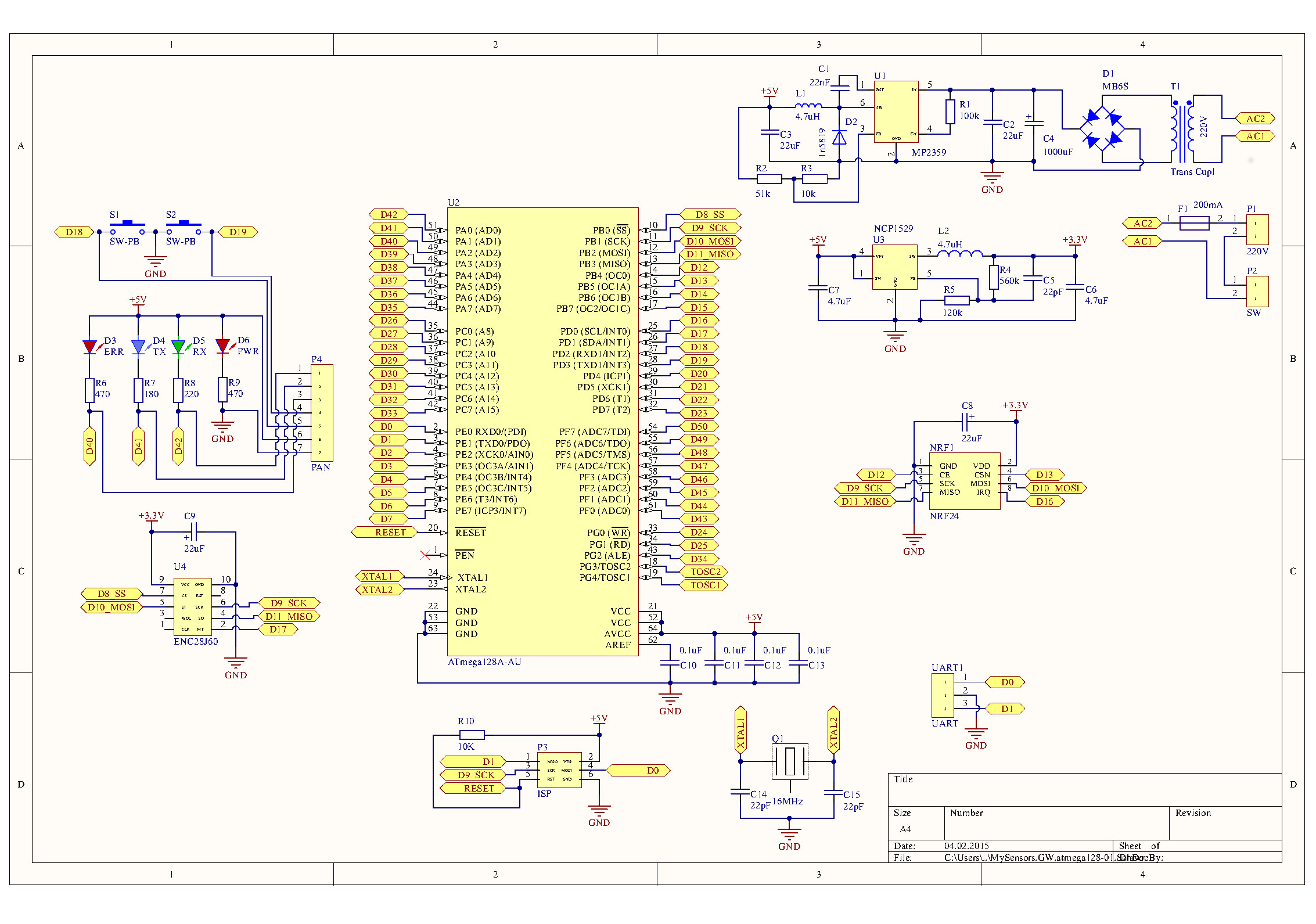
Custom made ethernet gateway based on atmega128
-
@axillent I'm currently supporting my scripts on both arduino and spark.io to avoid everybody reinventing the wheel. Hopefully spark.io is more a hardware provider, meaning they design and implement hardware of their own they afterward sell, or sponsor through indiegogo. They also already have a could cum IFTTT already working.
Currently mysensors is too much linked to the vera although it is opening up. With a gateway that would be automatically wifi or wired, as you plan to do, that would change this.
I understand the approch for a cheap board, but I guess that you would need more components in you BOM that just the ESP8266 plus some soldering on a board ? (I don't speak of this nice russian transformer ;-) but that would kill many people in between just soldering, no ?
@epierre nice value arduino provide is that you can do nice things with low entry barrier and without soldering
Mysensors is intend to use this value as much as possible."Solder or not solder" is a personal decision and mostly subject of the fan.
At least for me it is fan
as for device from this topic it is not share of the schematics, it is just share of a fan)
russian transformer is part of it (i have a german one but it is too weak for this particular application)as for ESP8266 - 4$ is the cost of a ready to use module. The only missing thing is radio, you will need to connect 5 wires to radio,
your BOM is simple - ESP module, nordic module and power supply
should be simple even without a special Mysensors board.
I see a good potential herealso I see a good potential on a future network topology discussed in a separate thread, I'm going to test myself an installation with multi hardware layer multi gateway MySensors network
-
@axillent which is something I actually do with all deversing into domoticz (vera, mysensors, spark core, webcam), and have an uniformized access through imperihome.
I'm very interrested about the wifi capacity if we cannot achieve some level of security within rf24.
-
I got an idea to improve my gateway by adding 433MHz receiver
I'm succeeded by adding it into the same dimensionAs discussed with @hek it will be other version of EthernetGateway sketch able to handle both NRF24 and RF433 reciever
Just a small change to schematic

-
@axillent which is something I actually do with all deversing into domoticz (vera, mysensors, spark core, webcam), and have an uniformized access through imperihome.
I'm very interrested about the wifi capacity if we cannot achieve some level of security within rf24.
@epierre About security within rf24 we are close. I have implemented and verified HMAC-SHA256 signing. I just need some more time to implement support for a pure software-alternative to the ATSHA204 as well and my "offering" will be complete. Check the security thread (I will post my update there once finished).
-
@Anticimex This is good news, that would make us a bit safer... next step will be two ways SSL encryption ;-)
-
@Anticimex This is good news, that would make us a bit safer... next step will be two ways SSL encryption ;-)
@epierre ha! Well, whoever wants encryption, feel free to do it :) I see no need so I'm skipping that though. I am fine with somebody potentially reading the sensor values and instructions I transmit. What concerns me is if somebody could fool my system and inject their own commands. But with my signing, I challenge anybody to try ;) (and I publish full sources)
-
I made a version with RF433 receiver, I'm able to fit it into the same size PCB & same size box
will work on the new code to support RF433 sensors. The idea is to use ID=254 for the single node which will holds all RF433 sensors as it's children. I will need to manage a special inclusion for RF433 sensors. I have two buttons and 3 leds. This probably will be used to select & indicate sensor type during inclusion. Sensor type and child ID will be stored in gateway EEPROM. For the controller sensors will behave as regular motions / fire / door / water leakage / etc. sensors
I have all this sensors connected to simple GSM alarm system. The advantage to connect the, to mysensors is a reuse. All sensors will be working simultaneously with alarm and mysensors
-
-
-
-
hey axillent,
Could you upload the source code of your gateway?
You use another slave that?(Type of This gateway send a RF to anther module and control de lamp?)
If Yes could you post the schema and de souce code?
Thx

